1
Hotwire® ADSL/R Bridge/Router, Model 6381
with Inline Phone Filter
Installation Instructions
Document Number 6381-A2-GN10-30
February 2004
Installation Procedures
To install the Hotwire ADSL/R Bridge/Router:
Verify the contents of the package and obtain the correct cables (see Package
Checklist on page 4 and Wiring and Cables You Need (not supplied) on page 4)
Install phone filters on all phones that will share the same phone line as the router
(see Installing Phone Filters on page 5)
Connect the router (see Installing the Hotwire ADSL/R Bridge/Router on page 6)
Verify that the front panel LEDs show the correct status (see LED Status on page 9)
If necessary, configure the router (see Configuring the Hotwire ADSL/R
Bridge/Router on page 10)
Definitions
The following terms are used in this booklet.
network
A group of connected things, such as telephones or computers.
bridge
A device that forwards any message from one part of a network to
another. The Hotwire ADSL/R Bridge/Router is shipped as a bridge.
router
A device that forwards messages according to their network
addresses. You must configure the Hotwire ADSL/R Bridge/Router to
make it work as a router.
POTS
Plain Old Telephone Service. The voice service provided over the
public switched telephone network (PSTN).
DSL
Digital Subscriber Line. The technology that allows you to use a POTS
line for both voice calls and high-speed Internet access
simultaneously.
ADSL
Asymmetric DSL. A version of DSL that allows a higher speed for
information coming from the Internet to your PC (“downstream”) than
it does for information going to the Internet from your PC (“upstream”).
ReachDSL
A proprietary Paradyne version of DSL that works on lines too long or
too noisy for ADSL.
ADSL/R
The technology that combines ADSL and ReachDSL in one device.
1
Software and Firmware License Agreement
ONCE YOU HAVE READ THIS LICENSE AGREEMENT AND AGREE TO ITS
TERMS, YOU MAY USE THE SOFTWARE AND/OR FIRMWARE INCORPORATED
INTO THE PARADYNE PRODUCT. BY USING THE PARADYNE PRODUCT YOU
SHOW YOUR ACCEPTANCE OF THE TERMS OF THIS LICENSE AGREEMENT.
IN THE EVENT THAT YOU DO NOT AGREE WITH ANY OF THE TERMS OF THIS
LICENSE AGREEMENT, PROMPTLY RETURN THE UNUSED PRODUCT IN ITS
ORIGINAL PACKAGING AND YOUR SALES RECEIPT OR INVOICE TO THE
LOCATION WHERE YOU OBTAINED THE PARADYNE PRODUCT OR THE
LOCATION FROM WHICH IT WAS SHIPPED TO YOU, AS APPLICABLE, AND YOU
WILL RECEIVE A REFUND OR CREDIT FOR THE PARADYNE PRODUCT
PURCHASED BY YOU.
The terms and conditions of this License Agreement (the “Agreement”) will apply to the
software and/or firmware (individually or collectively the “Software”) incorporated into
the Paradyne product (the “Product”) purchased by you and any derivatives obtained
from the Software, including any copy of either. If you have executed a separate written
agreement covering the Software supplied to you under this purchase, such separate
written agreement shall govern.
Paradyne Corporation (“Paradyne”) grants to you, and you (“Licensee”) agree to accept
a personal, non-transferable, non-exclusive, right (without the right to sublicense) to use
the Software, solely as it is intended and solely as incorporated in the Product
purchased from Paradyne or its authorized distributor or reseller under the following
terms and conditions:
1. Ownership: The Software is the sole property of Paradyne and/or its licensors. The
Licensee acquires no title, right or interest in the Software other than the license
granted under this Agreement.
2. Licensee shall not use the Software in any country other than the country in which
the Product was rightfully purchased except upon prior written notice to Paradyne
and an agreement in writing to additional terms.
3. The Licensee shall not reverse engineer, decompile or disassemble the Software in
whole or in part.
4. The Licensee shall not copy the Software except for a single archival copy.
2
5. Except for the Product warranty contained in the manual, the Software is provided
“AS IS” and in its present state and condition and Paradyne makes no other
warranty whatsoever with respect to the Product purchased by you. THIS
AGREEMENT EXPRESSLY EXCLUDES ALL OTHER WARRANTIES, WHETHER
EXPRESS OR IMPLIED, OR ORAL OR WRITTEN, INCLUDING WITHOUT
LIMITATION:
a.
Any warranty that the Software is error-free, will operate uninterrupted in your
operating environment, or is compatible with any equipment or software
configurations; and
b.
ANY AND ALL IMPLIED WARRANTIES, INCLUDING WITHOUT LIMITATION
IMPLIED WARRANTIES OF MERCHANTABILITY, FITNESS FOR A
PARTICULAR PURPOSE AND NON-INFRINGEMENT.
Some states or other jurisdictions do not allow the exclusion of implied warranties
on limitations on how long an implied warranty lasts, so the above limitations may
not apply to you. This warranty gives you specific legal rights, and you may also
have other rights which vary from one state or jurisdiction to another.
6. IN NO EVENT WILL PARADYNE BE LIABLE TO LICENSEE FOR ANY
CONSEQUENTIAL, INCIDENTAL, PUNITIVE OR SPECIAL DAMAGES,
INCLUDING ANY LOST PROFITS OR LOST SAVINGS, LOSS OF BUSINESS
INFORMATION OR BUSINESS INTERRUPTION OR OTHER PECUNIARY LOSS
ARISING OUT OF THE USE OR INABILITY TO USE THE SOFTWARE,
WHETHER BASED ON CONTRACT, TORT, WARRANTY OR OTHER LEGAL OR
EQUITABLE GROUNDS, EVEN IF PARADYNE HAS BEEN ADVISED OF THE
POSSIBILITY OF SUCH DAMAGES, OR FOR ANY CLAIM BY ANY THIRD
PARTY.
7. The rights granted under this Agreement may not be assigned, sublicensed or
otherwise transferred by the Licensee to any third party without the prior written
consent of Paradyne.
8. This Agreement and the license granted under this Agreement shall be terminated
in the event of breach by the Licensee of any provisions of this Agreement.
9. Upon such termination, the Licensee shall refrain from any further use of the
Software and destroy the original and all copies of the Software in the possession of
Licensee together with all documentation and related materials.
10. This Agreement shall be governed by the laws of the State of Florida, without
regard to its provisions concerning conflicts of laws.
3
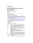
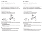
Package Checklist
Verify that your package contains the following:
Rea
chD
SL
PWR
ALM
TST
LINE
TX/R
X
ETH
ERN
ET
Hotwire 6381
ADSL/R
Bridge/Router
DSL interface cable
Power cord with
power transformer* with RJ11 connectors
Ethernet 8-pin
cable
Two ferrite clamps
* Some models are shipped with a desktop transformer and a separate, country-specific
power cord. Refer to the electrical ratings on the transformer for the proper AC line
voltage and frequency.
Wiring and Cables You Need (not supplied)
The following standard cables and connectors are used with this product:
Standard RJ11
(or RJ14) wall jack for
the DSL cabling
4
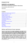
Installing Phone Filters
IC
E
SERV
P/N
TM
in
e
PROD
ad
L. AC
T.E
CE
. EQ
E1 SS
00 UIPMAR
29 Y
6 EN
T
R
M
UCT
Ch
geprufte
Sicherheit
TU
Y
Ph
o
08 ne
02 F
in
a
-3
Be / Fa 39
l Fu br
2se iquè 00
In Ch
c.
11 ina
98
ilt
er
E
N
LI
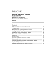
A phone filter is recommended to minimize
background noise during a phone conversation on
telephones not connected directly to the Hotwire
ADSL/R Bridge/Router. If additional telephones in
your home or business share the same phone line
with the router, install one phone filter on each
telephone. A fax machine or other equipment that
uses the same POTS line as the router must also use
a filter.
LR9
2997
E
N
O
PH
There are two Hotwire phone filters available:
Hotwire 6035 Universal Phone Filter is designed for use with a tabletop phone.
Hotwire 6040 Wall Jack Phone Filter is designed for use with a wall phone.
Customer
Premises
Router
RJ11
Wall
Jack
POWER
ETHER
NET
PHONE
RJ11
Wall Jack
LINE
6035
Phone Filter
6040
Wall Jack
Phone
Filter
03-17355
Contact your sales or service representative to order Hotwire phone filters.
5
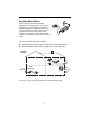
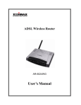
Installing the Hotwire ADSL/R Bridge/Router
Place the router on a flat surface with clearance for the rear connectors.
Procedure
1. UNPLUG TELEPHONE. If a telephone is connected at
the RJ11 wall jack where the router will be installed,
unplug the telephone cable from the wall jack.
2. RECONNECT TELEPHONE.
(Optional. Go to Step 3 if you are not
connecting a telephone to the router.)
RJ11
Wall Jack
PHONE
POWE
R
ETHERN
Plug the existing telephone cable that was
unplugged in Step 1 into the jack labeled
PHONE. The router has a built-in filter, so
no filter is required on this phone.
3. CONNECT DSL LINE. Use the supplied
RJ11 telephone cable for the ADSL/R line
connection. Insert one end of the cable into
the jack labeled LINE. Insert the other end
of the cable into the RJ11 wall jack.
ET
PHON
E LIN
E
LINE
PHONE
LINE
RJ11
6-pin
Interface
Cable
6
58
173
02-
RJ11
Wall
Jack
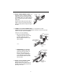
4. INSTALL WHITE FERRITE CLAMP. If you
plugged in a phone, install the supplied
white ferrite clamp around both the LINE
and PHONE cables. If you did not plug in a
phone, install the white clamp around the
LINE cable.
LINE
PHONE
PHONE
LINE
59
173
02-
Hold the open clamp around the cable or
cables as close to the router as possible.
Close the clamp and lock it by pressing on
the latch.
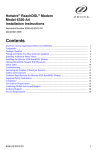
5. CONNECT TO PC OR ETHERNET HUB. Use an 8-pin Ethernet cable
(straight-through or crossover) for the Ethernet connection. Insert one end of the
cable into the jack labeled ETHERNET.
Connect to one of the following:
—
PC. Use an Ethernet standard,
straight-through cable and connect
the other end to a PC with an
Ethernet Network Interface Card
(NIC) installed.
ETHERNET
POWER
03-17360
-01
– or –
—
ETHERN
ET
PC with Ethernet
Network Interface
Card
Ethernet
Straight-Through
Cable
Ethernet Hub. Use an Ethernet
standard, straight-through cable
and connect the other end to an
Ethernet hub’s Uplink port. (To
connect to a hub’s standard port,
use an Ethernet crossover cable.
See the documentation that came
with your hub.)
ETHERNET
POWER
02-17361
-01
Ethernet
Hub
ETHERN
ET
1
2
3
4
5
6
7
6. INSTALL BLACK FERRITE CLAMP.
Hold the open clamp around the
Ethernet cable as close to the router as
possible. Close the clamp and lock it by
pressing on the latch.
7
8
Ethernet
Straight-Through
Cable
7. CONNECT TO POWER. Insert the round connector of the
transformer’s thin power cord into the jack labeled
POWER. If the transformer has a built-in plug, plug it into
an AC outlet. If the transformer has a separate power
cord, connect the cord to the transformer, then plug the
power cord into an AC outlet.
When the power cord is installed, the router goes through
a power-on self-test. LED Status on page 9 shows how
the LEDs should appear after a successful test.
POWER
POWER
Transformer
Installation is now complete.
If your Internet Service Provider (ISP) has instructed you to configure the Hotwire
ADSL/R Bridge/Router using the web interface, or if you would like to use the device as
a router, proceed to Configuring the Hotwire ADSL/R Bridge/Router on page 10.
Note to service provider: Each 6381 on the same subnet requires a unique IP address if
you wish to upgrade firmware or access it using the web interface.
8
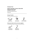
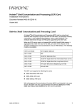
LED Status
The Hotwire ADSL/R Bridge/Router’s front panel includes LEDs (light-emitting diodes)
that show the status of the Bridge/Router. In Table 1, Front Panel LEDs, the Condition in
BOLD shows how the LED should appear after a successful power-on self-test.
PWR
ALM
TST
LINE
TX/RX
ETHERNET
ADSL/R
03-17357
Table 1. Front Panel LEDs
LED
Condition Status
PWR
ON
The router has power.
ALM
ON
An alarm condition exists.
OFF
No alarms have been detected by the router.
TST
–
(The TST LED is not used.)
LINE
ON
The DSL link is established.
OFF
No DSL link has been established.
Blinking
Data transmission is in progress on the DSL line.
OFF
No data is being transmitted or received by the router.
ON
The Ethernet connection is active.
OFF
No Ethernet device is detected.
TX/RX
ETHERNET
9
Configuring the Hotwire ADSL/R Bridge/Router
STOP. Do not proceed with this section unless you were so instructed by your
Internet Service Provider (ISP), or you are familiar with IP and routing protocols.
Depending on the requirements of your ISP, your Hotwire ADSL/R Bridge/Router may
have a web interface that you can access using Internet Explorer 6.0 or above. The web
interface is used to configure the router.
Configuration Table of Contents
Accessing the Web Interface ...................................................................................
Configuring DSL Modulation ...................................................................................
DSL Status .................................................................................................................
DSL Test .....................................................................................................................
Configuring PVCs and Connections .......................................................................
Modifying an Existing PVC ......................................................................................
Modifying an Existing Connection (NAT, Firewall) ................................................
Configuring DHCP ....................................................................................................
Changing the Bridge/Router’s IP Address .............................................................
Saving Changes, Restarting, and Restoring Factory Defaults .............................
Configuring the System Log ....................................................................................
Displaying the System Status ..................................................................................
Product Information ..................................................................................................
Remote Log ...............................................................................................................
Changing the Bridge/Router’s Password ...............................................................
Ping ............................................................................................................................
Game Servers, Application Servers, and Services ................................................
Bridge Options ..........................................................................................................
10
11
13
13
13
14
15
16
19
20
21
21
22
22
23
23
23
24
24
Accessing the Web Interface
Procedure
To configure the router using the web interface:
1. Start Internet Explorer 6.0 or above on a PC that is connected to the router directly
or through your hub.
2. Type the following into Internet Explorer’s address line:
http://192.168.1.1:8080
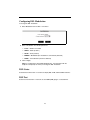
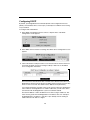
3. Press Enter. The Login screen appears.
4. Type the Name and Password exactly as they were supplied to you by your ISP.
Both Name and Password are Admin if your ISP uses the factory default.
5. Click on OK. The web interface main screen appears.
The main screen consists of four sections, called frames:
—
A header frame at the top of the screen
—
A menu frame on the left side of the screen
—
A content area in the middle of the screen
—
A status area at the bottom of the screen
11
The menu frame has the following selections:
Table 2. Web Interface Menu Selections
Menu Category
Drop-Down Menu Name
Menu Selections
DSL – Used to
configure and monitor
the DSL Wide-Area
Network (WAN)
Line
Modulation
Status
Test
ATM PVC
New
BridgeVC
Connection
New
Bridge
Existing Connections
Local – Used to
control and monitor
the Bridge/Router
Options
Commands
System Log
System Status
Product Information
Ethernet
Remote Log
User Management
Ping
Services – Used to
configure and monitor
the Ethernet Local
Area Network (LAN)
Options
DHCP Status
DHCP Configuration
Game Servers
Application Servers
Services
Bridge Options
Help – Provides
information about the
web interface
Topics
Introduction
Contents
12
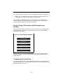
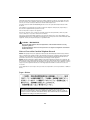
Configuring DSL Modulation
To change the DSL modulation:
1. Select Modulation from the DSL > Line menu.
2. Select a modulation from the drop-down list:
—
T1413 – ANSI T1.413-1998
—
GDMT – G.dmt (G.992.1)
—
GLITE – G.lite (G.992.2)
—
MMODE – Multi-Mode (the modulation is automatically detected)
—
NONE – No modulation (the link is disabled)
3. Click on Apply.
NOTE: In configurations with multiple bridged PVCs, communication with the
endpoint is temporarily lost when you change the DSL modulation.
DSL Status
Select Status from the DSL > Line menu to display DSL, ATM, and ReachDSL statistics.
DSL Test
Select Test from the DSL > Line menu to send OAM (ATM) pings to a selected PVC.
13
Configuring PVCs and Connections
The minimum configuration requires the definition of at least one Permanent Virtual
Circuit (PVC) and a Connection. The factory default configuration includes one PVC,
named BridgeVC, and one connection, named Bridge.
Defining a PVC
The PVC is an ATM Virtual Circuit used to communicate over the DSL link. The
Bridge/Router supports up to seven PVCs.
To create a PVC:
1. Select DSL > ATM PVC > New. The New PVC screen appears.
2. Enter a PVC Name and click on Next.
3. Enter the VPI, VCI and choose a QoS option:
—
UBR (Unspecified Bit Rate)
—
CBR (Constant Bit Rate)
—
VBR (Variable Bit Rate)
4. For CBR, enter the Peak Cell Rate (PCR). For VBR, enter the PCR and Sustainable
Cell Rate (SCR). Permitted values for both PCR and SCR are 0–10,000,000.
5. Click on Apply.
Defining a Connection
The Connection defines a communication method for a PVC.
To create a connection:
1. Select Connection > New. The New Connection screen appears.
14
2. Enter a Connection Name and choose a PVC and a communication method:
—
DHCP – Obtain an IP address automatically. This method uses the Dynamic
Host Configuration Protocol (DHCP) to obtain the IP address from the server.
The IP address is dynamically assigned and is not known prior to assignment.
—
PPPoA – PPP (Point to Point Protocol) over ATM is defined in RFC 2364. It is a
method of encapsulating PPP packets over ATM cells which are carried over
the DSL line. PPP is a method of establishing a session between network
hosts. It usually provides a mechanism of authenticating users.
—
PPPoE – PPPoE (Point to Point Protocol over Ethernet) is defined in
RFC 2516. PPPoE is a method of encapsulating PPP packets over Ethernet.
—
Static – Specify an IP address. Use this option if your ISP has assigned a
static IP address. Enter the IP address, subnet mask, and gateway as
instructed by your ISP. Up to three Domain Name Server (DNS) addresses can
also be specified. These allow you to have access to other web servers.
—
Bridged – The connection is bridged. The Bridge/Router acts as a hub, and
passes all packets across the DSL port. On a single-PVC system, the
upstream router must be on the same subnet as the Ethernet interface on the
Bridge/Router (see Changing the Bridge/Router’s IP Address on page 20).
3. Click on Next.
4. For PPPoA, PPPoE, or Static, enter the additional information required, as supplied
by your ISP. For PPPoA or PPPoE:
—
If you have multiple PVCs, verify that On Demand is set to Off
—
If you set Max Attempts to 0, set Keep Alive to a value other than 1
5. Click on Apply.
6. Select Local > Commands in the menu frame. Click on Save All Changes.
Modifying an Existing PVC
To modify a PVC already defined:
1. In the menu frame, select a PVC from the DSL > ATM PVC menu. The Modify PVC
screen appears. From this screen you can modify the VPI, VCI, and QoS, or delete
the PVC.
2. Click on Apply.
3. Select Local > Commands in the menu frame. Click on Save All Changes. Any
changes made only apply to the selected PVC.
15
Modifying an Existing Connection (NAT, Firewall)
To modify a connection already defined:
1. In the menu frame, select a connection from the DSL > Connection menu. The
Modify Existing Connection screen appears. From this screen you can modify the
connection information, or delete the connection.
2. Select Security Settings to enable or disable NAT and the firewall. (NAT must be
enabled for all connections or disabled for all connections.)
16
3. In the Security Settings screen, click on Settings to invoke the Firewall Setup and
Security Rules screen.
4. The firewall DMZ option allows one local user to be exposed to the Internet for use
of special-purpose services such as online gaming or videoconferencing. Enable
DMZ if desired, and type the local address into the Host field that subsequently
appears.
5. Selecting the Games Category from the Add New Rule drop-down menu invokes
the Available Rules In Games Category screen. Here you can specify any games
you are going to play by selecting Apply from the drop-down menu next to any
game. The Bridge/Router automatically configures the proper firewall pinholes.
6. Selecting the Apps Category from the Add New Rules drop-down menu invokes the
Available Rules In Apps Category screen. Select the applications you are going to
use by selecting Apply from the adjacent drop-down menus. The Bridge/Router
automatically configures the proper software portholes and blocks all other
applications.
7. Selecting the Services Category from the Add New Rules drop-down menu invokes
the Available Rules In Services Category screen. Select the services you are going
to use by selecting Apply from the adjacent drop-down menu. The Bridge/Router
automatically configures the proper software portholes and blocks all other
services.
17
8. Selecting the Special Category from the Add New Rules drop-down menu invokes
the Available Rules In Protected Category screen. Select the special functions you
are going to use by selecting Apply from the adjacent drop-down menu. The
Bridge/Router automatically configures the proper software portholes and blocks all
other functions.
9. The selected game, application, service, and special rules are added to the Firewall
Setup and Security Rules screen. Click on Save.
10. Select Local > Commands in the menu frame. Click on Save All Changes. Any
changes made apply only to the selected PVC.
If you require servers or services not already defined in the Bridge/Router, you can
define new rules. See Game Servers, Application Servers, and Services on page 24.
Change Route in Multi-PVC Configurations
Select Change Route from the Options menu on the Modify Existing Connection screen
to set a next-hop route for the connection, or a static route to an IP subnet that can be
reached through this connection.
This functions the same in a single-PVC or a multi-PVC configuration, except in the use
of the Default Gateway defined on the Local > Ethernet screen (see Changing the
Bridge/Router’s IP Address on page 20). In a multi-PVC configuration, Default Gateway
is the gateway of last resort: if there is no other route in the routing table, the
Bridge/Router sends the unknown packet to this gateway on whichever PVC is assigned
to the same subnet. However, if you configure a router address as a part of the DHCP
profile on the DHCP server, it overrides the default gateway when the DHCP client
receives its IP address. The same holds true if you check the box for Set Default Route
in the PPPoA or PPPoE setup screen.
You can tell if you have improperly configured a multi-PVC system by looking at the
routing table (Local > System Status > Route Table). If you have more then one route to
a destination of 0.0.0.0, it may be impossible to access the Bridge/Router from a remote
site. You must correct your DHCP or PPP configuration.
18
Configuring DHCP
By default, your Bridge/Router has LAN-side Dynamic Host Configuration Protocol
(DHCP) server disabled. This is necessary if you already have a DHCP server running
on your network.
To configure and enable DHCP:
1. Select DHCP Configuration from the Services > Options menu. The DHCP
Configuration screen appears.
2. Select DHCP Server and click on Settings. The DHCP Server Configuration screen
appears.
3. Click on the Status of udhcps-1 button to see the lease time for the PCs that have
connected via DHCP. Click on the Configure udhcps-1 button to see the DHCP
server configuration information:
The Lease Time is the amount of time a network user is allowed connection to the
Bridge/Router with their current dynamic IP address before it must be renewed. The
time is in units of seconds. The default value is 3600 seconds (60 minutes).
If you change the Start IP or End IP values, make sure the values are still within the
same subnet as the Bridge/Router’s IP address. Otherwise you will not be able to
communicate with the Bridge/Router if your PC has DHCP enabled.
The Start IP Address is where the DHCP server starts issuing IP addresses. This
value must be greater than the Bridge/Router’s IP address value. For example, if
the Bridge/Router’s IP address is 192.168.1.1 (the default), then the starting IP
address must be 192.168.1.2 or higher.
19
The End IP Address is the last IP address the DHCP server issues. The ending
address cannot exceed the subnet limit of 254, so the maximum value for the
End IP Address based on the default address is 192.168.1.254.
4. Select Local > Commands in the menu frame. Click on Save All Changes.
Changing the Bridge/Router’s IP Address
You can change the Bridge/Router’s IP address or specify that it is set by DHCP on the
Ethernet Configuration (Local > Ethernet) screen.
1. Select an IP Address Assignment type. The IP address assignment can be static or
assigned dynamically by a DHCP server. Select:
—
DHCP if you have another DHCP server on the network
—
Static if the Bridge/Router is the DHCP server for your network
2. If you select Static, enter an IP Address and Subnet Mask.
The DHCP server must have a fixed IP address. The DHCP server cannot move or
change because clients log onto the DHCP server to obtain IP addresses.
The default IP address is 192.168.1.1 and the default subnet mask is
255.255.255.0. This subnet mask allows the Bridge/Router to support 253 users,
which is its maximum.
3. Enter a Gateway address. The gateway is the routing device used to forward all
traffic that is not addressed to a station within the local subnet. Your ISP supplies
the Gateway Address.
4. Enter a Hostname. The hostname can be any alphanumeric word that does not
contain spaces.
5. Click on Apply.
20
6. If you changed the IP Address, access the Bridge/Router using the new address.
7. Select Local > Commands in the menu frame. Click on Save All Changes. If the
configuration is not saved, it is lost upon the next power reset.
If the Bridge/Router’s DHCP server function is disabled, you must configure the IP
address, subnet mask and DNS settings of every computer on your network. Do not
assign the same IP address to more than one computer.
Saving Changes, Restarting, and Restoring Factory
Defaults
Most changes made on the web interface screens are temporary. To permanently save
the Bridge/Router’s configuration, select Commands from the Local > Options menu.
Click on Save All Changes.
From this screen you can also restart the Bridge/Router, collect system information
(used for debugging), change the security status, and restore the Bridge/Router to its
factory defaults.
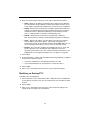
Configuring the System Log
You can display the system log by selecting System Log from the Local > Options menu.
Select Errors Only, Normal, or Tech Support, respectively, for minimized, standard, and
highly detailed views of the log.
21
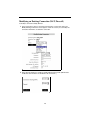
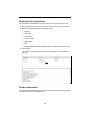
Displaying the System Status
You can display the Bridge/Router’s interface statistics on the System Status screen.
1. Select System Status from the Local > Options menu. The status screen appears.
2. Select one of the display options by clicking next to it:
—
Ethernet
—
ARP Table
—
Route Table
—
Memory Usage
—
Bridge MACs
—
DSL
—
BR2684 (NOTE: RFC 2684 bridge information is blank when PPPoA is active)
3. Click on Show.
For example, the following screen shows the system status screen with Ethernet
selected.
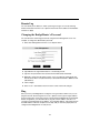
Product Information
You can display the Bridge/Router’s driver and run-time information by selecting Product
Information from the Local > Options menu.
22
Remote Log
You can identify an IP address to which system log messages are sent by selecting
Product Information from the Local > Options menu. Enter the IP address in the Add box
and click on Apply.
Changing the Bridge/Router’s Password
You can add users and change passwords using the User Management screen. For
example, to change the administrator password:
1. Select User Management from the Local > Options menu.
2. Type Admin in the Login Name field, if it is not already present.
3. Type the new password in the Password and Confirmed Password fields.
4. Optionally, change the Idle Timeout value. A user is logged off automatically after
this amount of time if no keyboard activity is detected. The default is 6000 seconds
(100 minutes).
5. Click on Apply.
6. Select Local > Commands in the menu frame. Click on Save All Changes.
Ping
Once you have your Bridge/Router configured, it is a good idea to make sure you can
ping the network. Select Ping from the Local > Options menu. Type the target address
that you want to ping. If you have your PC connected to the Bridge/Router via the default
DHCP configuration, you should be able to ping the network address 192.168.1.1. If
your ISP has provided their server address, try to ping that address. If the pings for both
the WAN and the LAN side complete successfully, and you have the proper protocols
configured, the Bridge/Router is ready for use.
23
Game Servers, Application Servers, and Services
You can view and change the Game Server, Application Server, and Services rules from
the Services > Options menu. These are the rules applied to a connection via the Add
New Rule menu on the Firewall Setup and Security Rules screen. (See Modifying an
Existing Connection (NAT, Firewall) on page 16.)
For example, to add a game server:
1. Select Game Servers from the Services > Options menu.
2. Click on Create New Rule. Two entry fields appear.
3. In Rule Name, enter a unique mnemonic containing 1 to 32 alphanumeric
characters and no spaces. For example: master_pastry_chef
4. In Rule Description, enter the full name of the game, or any other identifier. For
example: Master Pastry Chef
5. Click on Apply. The name is added to the Firewall Policy Database for Games
screen, at the end of the list.
6. Select Edit from the drop-down list adjacent to the new database entry. The rule edit
screen appears.
7. Click on Add to add a new protocol and port.
8. Select a protocol and enter a port, list of ports, or range of ports (according to the
option you select). Click on OK. The completed rule is added to the database.
Bridge Options
You can view and change Bridge Options from the Services > Options menu. The Bridge
Options screen allows you to turn on the Spanning Tree feature. Spanning tree is used
to detect whether multiple Ethernet hubs have been cabled together improperly. It is
normally not needed and should only be turned on if you are using multiple hubs behind
your Bridge/Router.
24
!
Important Safety Instructions
1. Read and follow all warning notices and instructions marked on the product or included in the manual.
2. Slots and openings in the cabinet are provided for ventilation. To ensure reliable operation of the product
and to protect it from overheating, these slots and openings must not be blocked or covered.
3. Do not allow anything to rest on the power cord and do not locate the product where persons will walk on
the power cord.
4. Do not attempt to service this product yourself, as opening or removing covers may expose you to
dangerous high voltage points or other risks. Refer all servicing to qualified service personnel.
5. General purpose cables are used with this product for connection to the network. Special cables, which may
be required by the regulatory inspection authority for the installation site, are the responsibility of the
customer. Use a UL Listed, CSA certified, minimum No. 24 AWG line cord for connection to the Digital
Subscriber Line (DSL) network.
6. When installed in the final configuration, the product must comply with the applicable Safety Standards and
regulatory requirements of the country in which it is installed. If necessary, consult with the appropriate
regulatory agencies and inspection authorities to ensure compliance.
7. A rare phenomenon can create a voltage potential between the earth grounds of two or more buildings. If
products installed in separate buildings are interconnected, the voltage potential may cause a hazardous
condition. Consult a qualified electrical consultant to determine whether or not this phenomenon exists and,
if necessary, implement corrective action prior to interconnecting the products.
8. Input power to this product must be provided by one of the following: (1) a UL Listed/CSA certified power
source with a Class 2 or Limited Power Source (LPS) output for use in North America, or (2) a certified
transformer, with a Safety Extra Low Voltage (SELV) output having a maximum of 240 VA available, for use
in the country of installation.
9. In addition, since the equipment is to be used with telecommunications circuits, take the following
precautions:
—
Never install telephone wiring during a lightning storm.
—
Never install telephone jacks in wet locations unless the jack is specifically designed for wet locations.
—
Never touch uninsulated telephone wires or terminals unless the telephone line has been
disconnected at the network interface.
—
Use caution when installing or modifying telephone lines.
—
Avoid using a telephone (other than a cordless type) during an electrical storm. There may be a
remote risk of electric shock from lightning.
—
Do not use the telephone to report a gas leak in the vicinity of the leak.
Notice to Users of the United States Telephone Network
The following notice applies to versions of the Hotwire ADSL/R Bridge/Router, Model 6381, that have been FCC
Part 68 approved.
This equipment complies with Part 68 of the FCC rules and the requirements adopted by the Administrative
Council for Terminal Attachment (ACTA). On the bottom side of this equipment is a label that contains, among
other information, a product identifier in the format US:AAAEQ##TXXXX. If requested, this number must be
provided to the Telephone Company.
This equipment is intended to connect to the Public Switched Telephone Network through a Universal Service
Order Code (USOC) type RJ11C or RJ14C jack. A plug and jack used to connect this equipment to the premises
wiring and telephone network must comply with the applicable FCC Part 68 rules and requirements adopted by
the ACTA. A compliant telephone cord and modular plug is provided with this product. It has been designed to be
connected to a compatible modular jack that is also compliant.
The Ringer Equivalence Number (or REN) is used to determine the number of devices that may be connected to
a telephone line. Excessive RENs on a telephone line may result in the devices not ringing in response to an
incoming call. In most but not all areas, the sum of RENs should not exceed five (5.0). To be certain of the number
of devices that may be connected to a line, as determined by the total RENs, contact the local Telephone
Company. The REN for this product is part of the product identifier that has the format US:AAAEQ##TXXXX. The
digits represented by ## are the REN without a decimal point. For example, 03 represents a REN of 0.3.
If the ADSL/R Bridge/Router causes harm to the telephone network, the Telephone Company will notify you in
advance that temporary discontinuance of service may be required. But if advance notice is not practical, the
Telephone Company will notify the customer as soon as possible. Also, you will be advised of your right to file a
complaint with the FCC if you believe it is necessary.
25
The Telephone Company may make changes in its facilities, equipment, operations or procedures that could
affect the operation of the equipment. If this happens, the Telephone Company will provide advance notice in
order for you to make necessary modifications to maintain uninterrupted service.
If trouble is experienced with the ADSL/R Bridge/Router, refer to the repair and warranty information in this
document.
If the equipment is causing harm to the telephone network, the Telephone Company may request that you
disconnect the equipment until the problem is resolved.
The user may make no repairs to the equipment.
Connection to party line service is subject to state tariffs. Contact the state public utility commission, public
service commission or corporation commission for information.
If the site has specially wired alarm equipment connected to the telephone line, ensure the installation of the
ADSL/R Bridge/Router does not disable the alarm equipment. If you have questions about what will disable alarm
equipment, consult your Telephone Company or a qualified installer.
! CANADA – EMI NOTICE:
This Class B digital apparatus meets all requirements of the Canadian interference-causing
equipment regulations.
Cet appareil numérique de la classe B respecte toutes les exigences du règlement sur le matérial
brouilleur du Canada.
Notice to Users of the Canadian Telephone Network
NOTICE: This equipment meets the applicable Industry Canada Terminal Equipment Technical Specifications.
This is confirmed by the registration number. The abbreviation IC before the registration number signifies that
registration was performed based on a Declaration of Conformity indicating that Industry Canada technical
specifications were met. It does not imply that Industry Canada approved the equipment.
NOTICE: The Ringer Equivalence Number (REN) for this terminal equipment is labeled on the equipment. The
REN assigned to each terminal equipment provides an indication of the maximum number of terminals allowed to
be connected to a telephone interface. The termination on an interface may consist of any combination of devices
subject only to the requirement that the sum of the Ringer Equivalence Numbers of all the devices does not
exceed five.
If your equipment is in need of repair, contact your local sales representative, service representative, or distributor
directly.
Japan – Notices
This is a Class B product based on the standard of the Voluntary Control Council for
Interference from Information Technology Equipment (VCCI). If this is used near a radio or
television receiver in a domestic environment, it may cause radio interference. Install and use
the equipment according to the instruction manual.
26
CE Marking
When the product is marked with the CE mark on the equipment label, a supporting Declaration of Conformity
may be downloaded from the Paradyne World Wide Web site at www.paradyne.com. Select Support →
Technical Manuals → CE Declarations of Conformity.
Declaration of Conformity
This Declaration of Conformity is made by Paradyne Corporation pursuant to Parts 2 and 15 of the Federal
Communications Commission’s Rules. This compliance information statement pertains to the following products:
Trade Name:
Model Number:
Hotwire
6381-Ax-2xx
This device complies with Part 15 of the FCC Rules. Operation is subject to the following two conditions: (1) this
device may not cause harmful interference, and (2) this device must accept any interference received, including
interference that may cause undesired operation.
The name, address, and telephone number of the responsible party is given below:
Paradyne Corporation
8545 126th Avenue North
Largo, FL 33773-1502
Phone: (727) 530-2000
The authority to operate this equipment is conditioned by the requirement that no modifications will be made to
the equipment unless the changes or modifications are expressly approved by Paradyne Corporation. The
supplied ferrite clamps must be installed as instructed to ensure compliance with Part 15, FCC Rules.
This equipment has been tested and found to comply with the limits for a Class B digital device, pursuant to Part
15 of the FCC Rules. These limits are designed to provide reasonable protection against harmful interference in a
residential installation. This equipment generates, uses, and can radiate radio frequency energy and, if not
installed and used in accordance with the instructions, may cause harmful interference to radio communications.
However, there is no guarantee that interference will not occur in a particular installation. If this equipment does
cause harmful interference to radio or television reception, which can be determined by turning the equipment off
and on, the user is encouraged to try to correct the interference by one or more of the following measures:
Reorient or relocate the receiving antenna.
Increase the separation between the equipment and receiver.
Connect the equipment into an outlet on a circuit different from that to which the receiver is connected.
Consult the dealer or an experienced radio/TV technician for help.
Supplier’s Declaration of Conformity
Place of Issue:
Paradyne Corporation
8545 126th Avenue North
Largo, FL 33773-1502
USA
Date of Issue:
02/26/2003
Paradyne Corporation, located at the above address, hereby certifies that the Hotwire® ADSL/R Bridge/Router
Model Number 6381-AX-210, bearing labeling identification number US:AW2DL03B6381-AX complies with: the
Federal Communications Commission's ("FCC") Rules and Regulations 47 CFR Part 68, the Administrative
Council on Terminal Attachments ("ACTA")-adopted technical criteria TIA-968-A, "Telecommunications Telephone Terminal Equipment -Technical Requirements for Connection of Terminal Equipment To the Telephone
Network, October 2002."
Patrick Murphy
Senior Vice President, Chief Financial Officer
27
Trademarks
Hotwire is a registered trademark of Paradyne Corporation. ReachDSL is a trademark of
Paradyne Corporation. All other products and services mentioned herein are the
trademarks, service marks, registered trademarks, or registered service marks of their
respective owners.
Notice to Service Providers
Consult any associated release notes before upgrading firmware. Both, when available,
will be found at www.paradyne.com. Select Support → Subscriber Firmware.
"
*6381-A2-GN10-30*
Copyright © 2004 Paradyne Corporation. Printed in U.S.A.
28