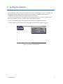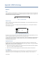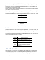
1
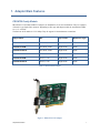
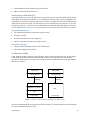
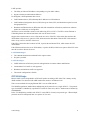
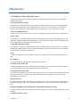
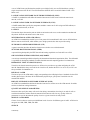
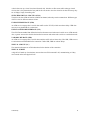
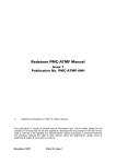
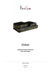
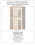
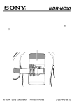
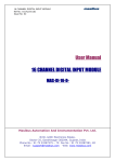
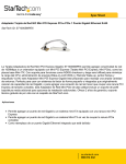
Fiber Optic ATM Adapters for PCI Bus, PROATM-V155 and PROATM-E155 Series User's Guide 05/06/2015, Version 4.2 Copyright © 2011 PROSUM PROSUM reserves the right to, without notice, modify all or part of this document and/or make any changes or improvements in any product and/or program described in this manual. PROSUM shall not be liable for any loss, cost or damage consequential to reliance on this manual. Limited Warranty PROSUM warrants (i) the manuals and the CDROM against material defects for a period of NINETY (90) DAYS, (ii) the hardware products against material defects and workmanship, under normal use and service, for a period of ONE YEAR, (iii) that the software-program licensed from it will perform substantially in conformance to the specifications in the related manuals for a period of NINETY (90) DAYS. These warranties are operative from the date of delivery to the end user. During the warranty period, PROSUM will repair or replace defective items at no charge. The warranty does not apply if the product has been damaged by accident or misuse, or has been modified without the written authorization of PROSUM. PROSUM has no liability to the end user or to any third party for consequential damages (including, but not limited to, loss of profits, downtime, damage of equipment or programs). PROSUM makes no warranty that its software products are error free and will work in combination with any hardware or software products provided by third parties. Trademarks and registered names All registered trademarks and registered product names mentioned herein, belong to their respective owners. ii Contents 1. ADAPTER MAIN FEATURES .............................................................................................................................. 5 PROATM FAMILY MODELS.......................................................................................................................................... 5 DRIVERS AND SOFTWARE ............................................................................................................................................ 7 FIBER CONNECTOR AND LED'S ..................................................................................................................................... 7 2. INSTALLING THE ADAPTER ON WINDOWS 2000/XP ....................................................................................... 8 I NSTALLING THE NDIS5 MINIPORT DRIVER ...................................................................................................................... 8 VERIFYING THE I NSTALLATION ....................................................................................................................................... 8 RFC2684 ................................................................................................................................................................. 8 PPPOA AND PPPOE(OA) ........................................................................................................................................... 8 SETTING UP IP OVER ATM FOR A PVC-ONLY ENVIRONMENT ............................................................................................ 8 Enabling IP over ATM: ......................................................................................................................... 8 Assigning the IP address to the computer: ............................................................................................ 9 Configuring the ATMARP Client for PVC's only: .................................................................................. 9 3. INSTALLING THE ADAPTER ON WINDOWS XP / VISTA / 7 / 8 ........................................................................10 PLATFORMS AND QUALITY OF SERVICE..........................................................................................................................10 I NSTALLING PROATM-WDM .....................................................................................................................................10 PROATM MANAGER .................................................................................................................................................10 PROATM-WDM DRIVER ...........................................................................................................................................11 MINIPORT ETHERNET DRIVER ......................................................................................................................................11 Virtual Ethernet Adapters ....................................................................................................................11 Setting Up an Ethernet Virtual NIC: ....................................................................................................11 IP Addresses ........................................................................................................................................11 4. INSTALLING THE ADAPTER ON LINUX ...........................................................................................................12 COMPILING THE LINUX DRIVER .....................................................................................................................................12 ATM FOR LINUX ........................................................................................................................................................12 BR2684 ...................................................................................................................................................................12 PPPOA AND PPPOE(OA) ..........................................................................................................................................12 FAST BACK-TO-BACK PVC CONNECTION.......................................................................................................................13 5. INSTALLING THE ADAPTER ON FREEBSD .....................................................................................................14 6. TESTING THE ADAPTER ..................................................................................................................................15 7. TECHNICAL SUPPORT AND REPAIR ...............................................................................................................16 CALLING FOR ASSISTANCE ..........................................................................................................................................16 RETURNING AN ADAPTER FOR REPAIR...........................................................................................................................16 8. TECHNICAL SPECIFICATIONS .........................................................................................................................17 APPENDIX: ATM TECHNOLOGY..............................................................................................................................18 BASICS ..................................................................................................................................................................18 Cells ....................................................................................................................................................18 Virtual Circuits....................................................................................................................................18 Signaling Protocols .............................................................................................................................18 The ATM Model ...................................................................................................................................18 Traffic Classes .....................................................................................................................................19 ATM WITH TRADITIONAL LANS ....................................................................................................................................19 Classical IP over ATM (RFC1577) ......................................................................................................20 LAN Emulation (LANE) .......................................................................................................................20 RFC2684 BRIDGE ....................................................................................................................................................21 ATM GLOSSARY ......................................................................................................................................................22 iii Figures FIGURE 1: PROATM-V155F ADAPTER ............................................................................................................................. 5 FIGURE 2: PROATM-E155 ADAPTER ............................................................................................................................... 6 FIGURE 3: PROATM.EXE MAIN W INDOW .............................................................................................................................15 FIGURE 4: ATM CELL FORMAT .........................................................................................................................................18 FIGURE 5: VIRTUAL CHANNELS AND VIRTUAL PATH ...............................................................................................................18 FIGURE 6: ATM MODEL LAYERS ......................................................................................................................................19 FIGURE 7: ATM + LANE COMPARED W ITH 802.3 OR 802.5 LANS ........................................................................................20 Tables TABLE 1: MODEL CHARACTERISTICS .................................................................................................................................. 5 TABLE 2: TRAFFIC CLASSES ............................................................................................................................................19 iv 1. Adapter Main Features PROATM Family Models PROATM-V155 and PROATM-E155 adapters are intended for servers and workstations. They are equipped with an SC-type duplex fiber connector. Depending on fiber type and adapter model, the transmission lengths are 2, 15, or 40 km. The data rate of all models is 155.52 Mbps. They all support 16384 simultaneous connections. Adapter Model Bus Type of fiber Maximum Length PROATM-V155F PCI 32-bit, 3.3/5V Multimode 2 km PROATM-V155FM PCI 32-bit, 3.3/5V Single mode 15 km PROATM-V155FLH PCI 32-bit, 3.3/5V Single mode 40 km PROATM-E155F PCIe x1, 3.3V Multimode 2 km PROATM-E155FM PCIe x1, 3.3V Single mode 15 km PROATM-E155FLH PCIe x1, 3.3V Single mode 40 km Table 1: Model Characteristics Figure 1: PROATM-V155 adapter Adapter Main Features 5 Figure 2: PROATM-E155 adapter Adapter Main Features 6 Drivers and Software The adapters come with drivers for Windows XP/Vista/7/8, Windows 2000/XP, Linux, and FreeBSD: Windows XP/Vista/7/8: The PROATM-WDM driver does not need the Microsoft ATM layers. As an autonomous driver, it allows for ATM connections based on Classical IP (RFC 1577) and multiprotocol (RFC 2684). Windows 2000/XP: The proatm NDIS5 Miniport driver is compatible with the ATM layers integrated by Microsoft into Windows 2000 and Windows XP. Linux: The Prosum proatm driver can run on kernel versions 2.6.xx and 3.xx.xx and is compatible with the "ATM for Linux" package. FreeBSD: The proatm and the patm drivers are compatible with the Host ATM Research Platform (HARP) software. The PROATM CDROM is bootable. It is based on FreeDOS and makes it possible to run a fast low-level diagnostic program independently of the PC OS in case of hardware problem suspicion. testam, a diagnostic utility running on Windows is provided with its source code as an example of ATM application on Windows. Fiber Connector and LED's The Duplex SC connector is adapted to 62.5/50 m multimode fiber (PROATM-V155F) or single mode fiber (PROATM-V155FM and PROATM-V155FLH).. Two LED's provide a status of the link and the driver activity: Red LED: Green LED: Adapter Main Features Physical link The card is driven by the software driver 7 2. Installing the Adapter on Windows 2000/XP The NDIS5 Miniport driver for Windows 2000/XP is fully compatible with the Microsoft NDIS5 specification. Installing the NDIS5 Miniport driver Please note that you must logon as system administrator to be able to install the driver, since it is not yet certified by Microsoft. Install the PROATM card on the target computer and power on the system Windows should detect a new hardware. Follow the Microsoft indications to install a driver from a known location, i.e., the PROATM CDROM or a folder containing the proatm.msi driver. Verifying the Installation Connect the optical fiber to an ATM switch or to another NIC. Make sure that the green and the red LED's are lit at the edge connector plate. Right-click the My network place icon and select Properties Make sure you see at least the ATM connection icon. NOTE: The ATM ELAN module (LAN EMULATION) is not useful for IP over ATM (Classical IP) connections. RFC2684 Windows XP includes an implementation of Internet RFC2684 Bridge. The implementation is an NDIS intermediate driver (Ethernet ATM Miniport) that looks like an Ethernet interface, but uses an ATM PVC to carry Ethernet frames. PPPoA and PPPoE(oA) Windows XP provides a PPPoA application that can be set up into the Call Manager. The PPPoA is seen as a modem that can be used when configuring a PPP remote access connection. There are some tricks when setting up this sort of connection. For example the value used as connection phone number must be set into the ATM connection properties into ATM Call Manager→ATM PVC Configuration→Application Usage→Match only to applications calling this address Windows XP includes the ability to create client Internet connections using PPPoE. The PPPoE looks for all Ethernet connections. If it finds an active Ethernet ATM Miniport virtual Ethernet adapter, it creates automatically a client PPPoE connection over ATM. Setting Up IP over ATM for a PVC-Only Environment Please, follow these steps to configure Windows 2000/XP Professional or Windows 2000/2003 Server computers such as they connect with Classical IP over ATM using PVC's: Enabling IP over ATM: In the Network Connections dialog box, select the Properties tab and then double-click on the ATM adapter to display all protocols bound to the ATM adapter. Installing the Adapter on Windows 2000/XP 8 Check the TCP/IP Protocol box. Assigning the IP address to the computer: Select Internet Protocol (TCP/IP) on the ATM Connection Properties page and click Properties. In the TCP/IP Properties dialog box, click Use the following IP Address, and then enter the appropriate information in the IP Address, Subnet Mask, and Default Gateway fields. Configuring the ATMARP Client for PVC's only: Select ATM Call Manager on the ATM Connection Properties page and click Properties. Click Properties from the ATM Call Manager dialog box. In the ATM PVC Configuration dialog box, enter the PVC name, VPI and VCI numbers, and then set the Application Type to ATM ARP. Installing the Adapter on Windows 2000/XP 9 3. Installing the adapter on Windows XP / Vista / 7 / 8 The PROATM-WDM drivers allow the PROATM adapters to work in a Windows environment without needing the Microsoft ATM stack available in Windows XP operating systems. PROATM-WDM includes a Windows WDM driver and a virtual Ethernet miniport driver emulating Classical IP (RFC 1577) and/or multiprotocol (RFC 2684). Platforms and Quality of Service This driver has been tested under the following environments: Windows XP, Windows 2003 server, Windows 2008 server, Windows Vista, Windows 7 and Windows 8 in 32-bit and 64-bit versions. It supports the UBR, CBR, and VBR qualities of service. Installing PROATM-WDM Please note that you must logon as system administrator to be able to install the driver, since it is not yet certified by Microsoft. 1. Install the PROATM adapter and power on the computer. 2. When Windows detects a new hardware, select Cancel to abort the installation. 3. Launch the proatmwdmsetup.exe setup utility. 4. The setup utility copies all PROATM-WDM files in the selected folder (by default: c:\program files\prosum\proatm-wdm ). 5. Then the setup utility proposes to go ahead with the driver installation. Do not uncheck Launch Driver Installation. 6. If a security dialog box opens to get some confirmation, accept everything. This Installation process may take a long time (especially on Windows Vista). Do not stop the process, even if you are asked for this by Windows. 7. After the setup completes correctly, the PROATM WDM driver is installed, as well as the virtual Ethernet adapter. You can modify the driver settings or add new virtual Ethernet adapters by using the PROATM Manager utility. You can find a shortcut in the desktop. PROATM Manager This program allows you to check the installed drivers, to change their settings, and to add and/or remove virtual Ethernet adapters. Installing the Adapter on Windows XP/Vista/Seven 10 PROATM-WDM Driver You should see as many WDM drivers as PROATM adapters are installed into your computer. You can change the setup of each ATM adapter, but notice that most of time this is not recommended. Miniport Ethernet Driver The Miniport driver emulates NIC's that are seen as classical Ethernet adapters by Windows but connect to ATM networks via permanent virtual circuits (PVCs). Virtual Ethernet Adapters During the installation process, an Ethernet virtual NIC is installed. By default, this NIC transmits and receives over the ATM network by using the CLASSICAL IP protocol through the PVC 0, 32. To modify these settings, select the virtual adapter and click Settings. To add new virtual adapters click Add New. You will be asked for some parameters and a new virtual adapter will be added to the current list. Setting Up an Ethernet Virtual NIC: LAN Protocol Encapsulation You can select here the protocol used to carry the Ethernet packets through the ATM. Two protocols are possible: Classical IP over PVC's as described in the RFC 1577 and Multiprotocol as described in the RFC2684. Max Frame Size Specify here the maximum size of IP packets that are transported by the ATM protocol. The default value is 9180. Locally Administered MAC Address Check this box to replace the Ethernet MAC address assigned by default to the virtual adapter, with a custom address. You must enter exactly 12 hexadecimal digits. ATM VPI Number, ATM VCI Number: Enter the VPI and VCI values to select the ATM channel that must be used to transport the Ethernet packets. Quality of Service Defines the quality of service used by the ATM channels. Choose from among: UBR, CBR, and VBR Use Multiple VC's You can check this box only when Classical IP is selected as ATM protocol. When this box is checked, you can add several VC's to distribute the traffic on several channels. IP Addresses On the contrary of the Microsoft ATM stack, PROATM-WDM makes it possible to associate several IP addresses with specific PVC's. You just need to create one virtual Ethernet adapter for each association. Please note that you can even bind several PVC's to each IP address by checking Use Multiple VC's. Installing the Adapter on Windows XP/Vista/Seven 11 4. Installing the Adapter on Linux The PROATM-V155 and PROATM-E155 adapters are based on the IDT77252 SAR. The IDT77252 driver provided by the Linux distribution has been developed for a competitor card model and does not fully support the Prosum PROATM 155 Mbps cards. We don't discourage the use of this driver if it can fit your requirements, but of course we cannot provide technical support concerning its usage with our cards. Prosum provides the proatm driver, which is an adaptation of the nicstar driver. Be aware that this README does not apply to the former nicstar2 driver. The proatm driver is compatible with kernel versions 2.6.xx and 3.0.xx. It supports the following features: - all PCI and PCIe Prosum ATM card models, - 16384 VC's - vpi_base and vci_base parameters permitting to use any VPI/VCI - UBR, CBR, ABR and VBR traffics, - AAL5 and AAL0 (IDT AAL0 or raw cells), - OAM cells (automatic responses sent by the driver) - x86_64 architecture Compiling the Linux Driver There are 2 ways for building and installing the proatm driver: building the module in an external folder or patching the kernel. Please refer to the README.pdf document “PROATM ADAPTERS ON LINUX” that come with the proatm-linux.tgz package on Prosum web site or in the PROATM CDROM. ATM for Linux You should then install the LINUX-ATM package. Take it from your distribution or download it from the ATM on Linux project from the SourceForge web site: http://sourceforge.net/projects/linux-atm. ATM on Linux is an experimental software that supports raw ATM connections (PVC's and SVC's), IP over ATM, LAN emulation, MPOA and a lot of utilities. Read carefully the USAGE file to learn how to compile, install and use this software. br2684 Recent kernels include the br2684 module that can handle RFC1483/2684 bridged PDU's. By using the br2684ctl utility, it is possible to set up several nas. Each nas is a logical Ethernet interface handling one ATM PVC with bridged-2684 (SNAP) encapsulation. In fact ATM is just used as a carrier. PPPoA and PPPoE(oA) A PPPoA client or server can be implemented by using the pppoatm plug-in for pppd. Add a line in the pppd configuration file specifying that you want to use the pppoatm plug-in with a certain vci.vpi: … plugin pppoatm.so vpi.vci … The rest is only usual pppd configuration. Installing the Adapter on Linux 12 A PPPoE(oA) client or server can be implemented by using rp-pppoe or pppoe-server and starting them so that they use a nas interface previously setup with br2684ctl. # # # # modprobe br2684 br2684ctl -b -c 0 -e x -a vpi.vci ifconfig nas0 up pppoe-server –I /dev/nas0 –L ip –R ip … pppoe-server can dialog with the RFC2684 implemented by the PROATM-WDM driver. Unfortunately, it is not compatible with the Windows 2000/XP RFC2684 implementation that does not accept packets smaller than 64 bytes. If you plan to use the ATM to connect a Microsoft client to a Linux box running pppoe-server, a light modification of pppoe-server is needed to force the minimum sent packet size to 64 bytes. Fast Back-to-back PVC Connection It is possible to connect two computers without any ATM switch. Here is a shell-script example you can adapt to your environment to start an IP over ATM (CLIP) connection via a PVC (0.100 in this example) between two computers: #!/bin/sh modprobe nicstar atmarpd -b atmarp -c atm0 ifconfig atm0 my_computer_ip up sleep 2s atmarp -s other_computer_ip 0.0.100 On this example we show two machines with IP addresses other_computer_ip and my_computer_ip. The script is for my_computer. Exchange the ip addresses on the other machine. After having run this shell script on each machine, you should be able to communicate via usual applications based on TCP/IP such as nfs, ftp, etc. Try first a simple ping. Refer to linux-ATM documentation for more complex configurations. Installing the Adapter on Linux 13 5. Installing the Adapter on FreeBSD The Prosum proatm driver for FreeBSD can be used with kernel versions 3.5, 3.51, and 4.1. It supports the the PROATM-155xx and the PROATM-V155xx models for the UBR, CBR and VBR QoS. It is compatible with the Host ATM Research Platform (HARP) software. This driver has been integrated into the FreeBSD distribution. For more recent kernels, it has been replaced with the patm driver developed by Hartmut Brandt. We recommend you use the FreeBSD driver version. You can get additional information about the driver and the HARP configuration from the README file provided with our old driver version. Installing the Adapter on FreeBSD 14 6. Testing the Adapter We recommend you carry out a test of the adapter after repairs and each time you suspect a problem. The PROATM diagnostic utility permits to verify the correct working of the adapter and its hardware compatibility with the computer. It does NOT permit to run a loop test. proatm.exe runs on DOS only. The simplest way for launching this test is to boot your computer on the PROATM CDROM. Then type “proatm” at the console prompt (FreeDOS). proatm.exe helps differentiate hardware defaults from software or configuration problems. The main window gives the characteristics of the adapter(s) detected in the computer (Figure 3). Figure 3: proatm.exe Main Window Testing the Adapter 15 7. Technical Support and Repair Calling for Assistance PROSUM has made every effort to ensure that the product you have purchased is free of defaults. All hardware and software parts have been tested individually and subjected to strict quality control procedures. Nevertheless, if you experience problems, contact your local distributor or send an Email to PROSUM: [email protected] If possible try to give the following information: 1. Computer mark and model. 2. Other extension boards installed in the computer. 3. Operating system name and version. 4. Topology, cabling. 5. Problem description and reproduction. Returning an Adapter for Repair There is no charge for repair or replacement of products under warranty. If you think the adapter has a hardware failure, please contact your local distributor or PROSUM as mentioned above before returning the card. 1. Include your name, your complete address and the description of the problem inside the package: 2. Send the product prepaid and packaged for safe shipment - if possible in its original container. The repaired or replaced adapter will be returned to you at PROSUM's expense. Technical Support and Repair Prosum does not accept packages with due port 16 8. Technical Specifications SAR IDT 77252 Theoretical Network Data Transfer Rate (OC3) : 155.52 Mbps Full Duplex Practical Data Transfer Rate : 135 Mbps Simultaneous connections: 16384 VPI/VCI: 14-bit encoding ATM and SONET Standard Compliance: SONET/SDH, STS/STM-1/OC3 AAL5, AAL0, CBR, VBR, UBR, ABR (SAR) UNI 3.0, UNI 3.1 (ILMI included) LAN Emulation (LANE) v1.0 Classical IP (CIP - RFC 1577) PROATM-V155F Multimode Fiber Port: multimode fiber, max 2 km. Connector: Duplex SC Wavelength: 1310 nm Sensitivity: -29 dBm Output Power: -20 to -14 dBm Maximum power on input: -14 dBm PROATM-V155FM Single mode Fiber Port: single mode fiber, max 15 km. Connector: Duplex SC Wavelength: 1310 nm Sensitivity: -38 dBm Output Power: -15 to -8 dBm Maximum Input Power : -6dBm Class I laser product compiles with IEC 60825-1 Complies with Telcordia GR-468-CORE PROATM-V155FLH Single mode Long Reach Fiber Port: single mode fiber, max 40 km. Connector: Duplex SC Wavelength: 1310 nm Sensitivity: -38 dBm Output Power: -8 to -5 dBm Maximum Input Power : -6dBm (does not support a loop-back without an attenuator) Class I laser product compiles with IEC 60825-1 Complies with Telcordia GR-468-CORE On board memory: 2 MB Indicators: Red: Network Link Green: Driver is running PCI Bus: 3.3V/5V, 32-bit, version 2.2 Operating Voltage and Current: 5V, 1 A max Operating Temperature: 5° C to 50° C (41° to 131° F) Operating Humidity: 10% to 90%, non condensing MTBF: 700 000H Size: 125 mm x 82 mm Compliance: FCC Part-15 class B CE Marking : Safety: EN50082-1 Emissions: EN 55022 Class A RoHS: 5/6 Technical Specifications 17 Appendix: ATM Technology BASICS Cells ATM (Asynchronous Transmit Mode) is a switching data transmission technology based on fixed-length cells (5-byte header and 48-byte payload). Each cell contains information in its header, essential to routing the cell and ensuring that the cell reaches its destination. 1 6 Header 53 Payload Figure 4: ATM cell format Virtual Circuits ATM is a connection-oriented technology. Before transmitting data, a source must establish virtual circuit (a bi-directional connection). ATM circuits are of two types: virtual paths (VP) and virtual channels (VC). A virtual path is a bundle of virtual channels (Figure 5.). VC1 VC2 VP VCn Figure 5: Virtual channels and virtual path The header of each cell includes the virtual path identifier (VPI) and the virtual channel identifier (VCI). The VPI/VCI combination identifies a unique virtual circuit in a particular switch. A virtual circuit can be permanent or created at connection time. The network administrator must manually set up permanent Virtual Circuits (PVC). Switched Virtual Circuits (SVC) are automatically established and closed through signaling protocols. Signaling Protocols In order to set up or to close SVC, signaling protocols send and receive packets on a well-known virtual channel (VPI=0, VCI=5). The format of the packets depends on the type of interface. Two types of interfaces defined by the ATM Forum coexist in ATM networks: UNI (user-network interface) applying to the connections between final switches and systems (computers, routers, etc), or public switches and private switches. NNI (network-network interface) applying to the connections between switches of the same level. The ATM Model ATM standards define protocols that operate at the data-link layer level of OSI model. These protocols are distributed in two layers: the ATM adaptation Layer (AAL) and the ATM layer. These two layers are ATM Technology 18 intercalated between the high layers (TCP/IP, LAN Emulation, etc) and the physical layer, which manages the phenomena related to medium of transmission. The ATM layer deals with the commutation and the multiplexing of the cells. It delivers ATM cells to the physical layer for transport through the network. The AAL layer adapts high layers and ATM world. It contains the process of segmentation and re-assembly (SAR) and the Convergence Sub layer (CS). The SAR segments each packet coming from high layers into ATM cells for the ATM layer. Conversely the SAR reassembles incoming ATM cells into packets in a form expected by high layers. The CS maintains for the high layers the quality of service (QoS) that is defined for its traffic class. The high layers are assured that the network will deliver that QoS for the life of the connection. High Layers ATM Adaptation Layer (AAL) ATM Layer Physical Layer Figure 6: ATM Model Layers Traffic Classes The concept of traffic classes comes from the world of telecommunications. As in telephone networks, with each connection is associated a sort of contract that defines the behavior that the network must respect (QoS). The idea is to make the network able to transport different traffic types for high-bandwidth applications such as voice, data, and video. To meet the user's needs for high-bandwidth networks, ATM standards define four traffic classes associated with five AAL protocols (AAL1 with AAL5 (Table 2). Traffic Class Traffic Description and Example A (AAL1) Constant Bit Rate (CBR), Connection-oriented, Synchronous traffic (uncompressed voice and video) B (AAL2) Variable Bit Rate (VBR), Connection-oriented, Synchronous Traffic (compressed voice and video) C (AAL3/4) Variable Bit Rate (VBR), Connection-oriented Asynchronous Traffic (X25, TCP/IP, Frame Relay, …) D (AAL5) Variable Bit Rate (VBR), Available Bit Rate (ABR), Connectionless, Asynchronous Traffic (LAN, TCP/IP, Frame Relay, …) Table 2: Traffic Classes ATM with Traditional LANs Taking into account the enormous base of installed Ethernet and Token-Ring LANs, it was important for ATM networks to be able to support the existing applications. Several standards make it possible today. CLASSICAL IP OVER ATM worked out by the IETF (Internet Engineering Task force) ATM Technology 19 LAN Emulation (LANE) developed by the ATM Forum MPOA developed by the ATM Forum Classical IP over ATM (RFC1577) Classical IP enables you to route IP packets over an ATM network. Each end station knows both its IP and ATM addresses and sends these addresses to an ATM address resolution protocol server (ATMARP). The ATMARP server maintains an address table and uses this table to translate between IP and ATM addresses within a single virtual sub network. The end stations query the ATMARP server for each SVC set-up. If an end station is using PVC's, the ATM network administrator must manually map the IP addresses to virtual circuits. When the SVC or PVC is set up, the end stations use the connection to send and receive IP packets. Classical IP Disadvantages: The communication between sub-networks requires routers. No QoS is provided. Broadcasts and multicasts are not supported. Only IP is supported. Other protocols cannot be used. Classical IP Advantages: CIP provides the advantages of IP on a fast ATM network. The network configuration is flexible. LAN Emulation (LANE) LANE emulates the MAC sub layer of the OSI model, which is used by all classical LANs. In other words, LANE makes an ATM network look and behave like an Ethernet or Token-Ring LAN. Thanks to this principle, the ATM network is invisible to the existing protocols and applications such as IP, IPX, NetBios, DECnet, etc. (Figure 7). Higher Layers Higher Layers IP/IPX/NetBios/etc. IP/IPX/NetBios/etc. NDIS/ODI NDIS/ODI LAN Emulation Adaptation Layer (AAL5) MAC ATM Physical Layer Physical Layer Figure 7: ATM + LANE compared with 802.3 or 802.5 LANs In the LAN Emulation Model, end systems (end stations, bridges etc.) directly attached to the ATM network are called LAN Emulation Clients (LEC). ATM Technology 20 LANE provides: The ability to find an ATM address corresponding to a given MAC address, Support of multicast and broadcast addresses. For doing that, LANE implements three servers: LAN Emulation Server (LES) that maps MAC addresses to ATM addresses. LAN Emulation Configuration Server (LECS) that gives clients (LEC) the information required to reach the appropriate LES, Broadcast and Unknown Server (BUS) that deals with transmission of broadcast, multicast or unknown packets in a similar way as a bridge does. All of these servers and clients connect to each other using SVC's or PVC's. The LEC's convert Ethernet or Token-Ring frames into cells and send these cells over the virtual circuits. Suppose that a station wants to access a file stored on a server. If the LEC of the station does not know the ATM address of the server, it queries its LES, which returns the information. Then the LEC of the station is able to set up a SVC to the LEC of the server. If the LEC of the station does not know its LES, it queries the well-known LECS, which returns the LES ATM address. If the LES does not know the server ATM address, it queries the BUS, which in turn queries all the LEC in the network in order to discover the server. LANE Disadvantages: The communication between emulated LANs requires routers. No QoS is provided. LANE Advantages: LANE enables non-ATM aware protocols and applications to connect without modifications. Connectionless LAN traffic is well supported. Broadcasts and multicasts traffic are supported. The network configuration is flexible. RFC2684 Bridge Ethernet traffic can be encapsulated in ATM AAL5 packets according to RFC2684. This is mostly used by ADSL modems. The subscriber-side ADSL modem can connect to an Ethernet LAN. There are two methods for carrying Ethernet PDU's over an ATM network. The "LLC Encapsulation" method allows multiplexing of all protocols over a single ATM VC. The protocol type of each PDU is identified by a prefixed LLC header. In some cases, the LLC header must be followed by a SNAP header. In the "VC Multiplexing" method, each ATM VC carries PDU's of exactly one protocol type. When multiple protocols need to be transported, there is a separate VC for each . ATM Technology 21 ATM Glossary ASYNCHRONOUS TRANSFER MODE (ATM) A high-speed, connection-oriented, data transmission technology that transmits fixed-size cells rather than variable-length packets. ATM ADAPTATION LAYER The highest layer of the ATM model, which roughly corresponds to the network layer of the Open Systems Interconnection (OSI) model. The ATM adaptation layer consists of four AAL protocols, each of which formats packets differently to support different types of transmissions, such as audio, video, and data. ATM-ATTACHED DEVICE A device, such as an end station, file server, router, or bridge that is directly connected to the ATM network. ATM LAYER The middle layer of the ATM model that sits between the physical layer and the ATM adaptation layer. The ATM layer roughly corresponds to the data-link layer of the OSI model. Standards at the ATM layer specify how to establish, clear, and maintain ATM virtual circuits. AVAILABLE BIT RATE (ABR) An ATM service category that is used for data traffic. The ABR category can tolerate delays. For each data transmission, ABR negotiates a range of acceptable bandwidths and an acceptable cell loss ratio (the number of cells that can be lost in any transmission). CELL A small, fixed-length packet. ATM cells are 53 bytes long, comprised of a five-byte header and 48 bytes of data. CELL-RELAY A type of network that transmits data in cells rather than in packets. CLASSICAL IP OVER ATM An Internet Engineering Task Force (IETF) standard that enables you to route Internet Protocol (IP) packets over an ATM backbone by encapsulating IP packets inside ATM cells. CONSTANT BIT RATE (CBR) An ATM service category that is used for time-sensitive traffic such as audio and video. CBR guarantees that audio and video cells arrive on time, with a minimal variation in the spacing between cells, by reserving bandwidth for a virtual circuit. EMULATED LAN In a LAN emulation (LANE) environment, an emulated LAN is a virtual network made up of end stations on more than one physical LAN. These workstations communicate as if they were located on the same physical LAN. INTEGRATED PRIVATE NETWORK-TO-NETWORK INTERFACE (IPNNI) A routing protocol for ATM that enables IP and ATM routing devices to share information about the network topology. LAN EMULATION (LANE) ATM Glossary 22 A set of ATM Forum specifications that enables you to bridge LANs over an ATM backbone, creating a single virtual network or ELAN. The ATM Forum has defined LANE 1.0 and will finalize LANE 2.0 in March 1997. LAN EMULATION NETWORK-TO-NETWORK INTERFACE (LNNI) A LANE 2.0 standard that will define the interface between two LANE servers within the same virtual network, or ELAN. LAN EMULATION USER-TO-NETWORK INTERFACE (LUNI) A LANE standard that specifies the components needed to connect two LANs using an ATM backbone, to create one virtual network, or ELAN. LATENCY The time that lapses between the point at which an end station seeks access to the transmission medium and the point at which the end station receives that access. MULTIPROTOCOL OVER ATM (MPOA) An ATM Forum standard that enables you to route protocols from traditional LANs over an ATM backbone. MPOA contrasts with LANE, which enables you to bridge protocols but does not provide routing. NETWORK-TO-NETWORK INTERFACE (NNI) A generic term that describes the interface between two switches on a switched network. NEXT HOP ROUTING PROTOCOL (NHRP) A protocol being developed by the IETF that will add routing capabilities to Classical IP over ATM. OPEN SYSTEMS INTERCONNECTION (OSI) MODEL A seven-layer networking model developed by the International Standards Organization (ISO). The OSI model is a guideline for developing standards to enable dissimilar network computing products to communicate. PERMANENT VIRTUAL CIRCUITS (PVCS) Virtual circuits that the network supervisor or ATM service provider sets up when configuring the ATM network. Bandwidth is always reserved for the virtual circuit, whether the PVC is in use or not, so PVC's are always available for immediate use. PHYSICAL LAYER The lowest layer of the ATM model, roughly corresponding to the OSI physical layer. Standards for the ATM model's physical layer, like those for the OSI model's physical layer, specify how to send bits over the transmission medium. PRIVATE NETWORK-TO-NETWORK INTERFACE (PNNI) An ATM Forum standard that defines the interface between two switches on an all-ATM network. It enables switches to distribute routing information. QUALITY OF SERVICE PARAMETERS Parameters that specify how many cells can be lost during a transmission, how long it can take for cells to reach their destination, and how much the amount of time between cells can vary. Quality of Service parameters are used to determine the quality of service a given virtual circuit will provide. SERVICE CATEGORIES Classes of service that are used to provide different levels of service for different types of traffic. ATM service categories are CBR, VBR, UBR, and ABR. SWITCH ATM Glossary 23 A device that sets up a virtual circuit and forwards cells. Switches act like routers while setting up virtual circuits; that is, they determine the best path for the cells to take. Once the virtual circuit has been setup, they act as bridges, simply forwarding cells. SWITCHED VIRTUAL CIRCUITS (SVCS) Virtual circuits that ATM end stations establish on-demand, when they need to communicate. Different types of SVC's exist for different amounts of time. UNSPECIFIED BIT RATE (UBR) An ATM service category that is used for data traffic such as TCP/IP, which can tolerate delays. UBR does not reserve any bandwidth for a connection. USER-TO-NETWORK INTERFACE (UNI) The ATM Forum standard that defines the interface between an end station and a switch on an ATM network. Also, a generic term used to describe the interface between an end station and a switch on a switched network. VARIABLE BIT RATE (VBR) An ATM service category that is used for time-sensitive traffic such as frame relay. Like CBR, VBR reserves a certain amount of bandwidth for the connection. Unlike CBR, VBR can tolerate delays. VIRTUAL CIRCUIT (VC) The connection between two ATM end stations for the duration of the connection. VIRTUAL SUBNET A logical LAN made up of end stations on more than one ATM-connected LAN, communicating as if they were located on the same physical LAN ATM Glossary 24