1
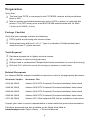
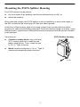
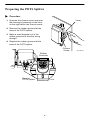
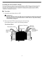
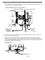
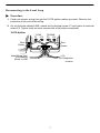
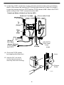
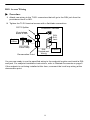
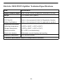
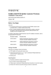
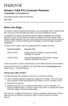
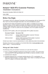
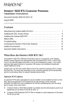
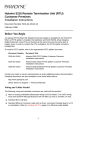
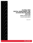
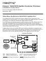
Hotwire 5030 POTS Splitter Customer Premises
Installation Instructions
Document Number 5030-A2-GN10-20
December 1999
What Does the Hotwire 5030 POTS Splitter Do?
The Hotwire 5030 POTS Splitter and Hotwire endpoints are components in the
Hotwire RADSL Access System. This system provides high-speed Internet or corporate
LAN access over traditional twisted-pair copper telephone wiring.
The POTS (plain old telephone service) splitter blocks out the DSL (Digital Subscriber
Line) signal and allows the POTS frequencies to pass through. At the customer
premises, the RADSL (Rate Adaptive Digital Subscriber Line) endpoint and telephone
can function simultaneously over the same pair of copper wires when a POTS splitter is
used at both ends of the local loop.
Copper pairs run from the central office to the customer premises to create the local
loop. The local loop terminates on the customer premises at the demarcation point in a
punchdown block or NID (network interface device). Wiring is connected from the
demarcation point to the customer premises POTS splitter and to the DSL jack.
Customer Premises
Demarcation
Point
POTS
Splitter
POTS
Central
Office
Local Loop
Network
Service
Provider
End-user
Systems
DSL
Jack
POTS/DSL
Punchdown
Block or NID
RADSL
Endpoint
Hub
98-16608a
DSL – Digital Subscriber Line
NID – Network Interface Device
POTS – Plain Old Telephone Service
RTU – Remote Termination Unit
New Wiring Connections
Existing Wiring (POTS)
1
Preparation
Verify that:
- The local loop POTS is connected to the POTS/DSL network at the punchdown
block or NID.
- New or existing unshielded twisted-pair wiring (CAT3 or better) is used with this
product. The CAT3 wiring must meet EIA/TIA-568 specifications with 24 AWG
(.5 mm) or 26 AWG (.4 mm).
Package Checklist
Verify that your package contains the following:
- POTS splitter and housing with closure screw.
- Small plastic bag with two 8–15 x 1″ Type A combination Phillips/slotted-head
screws and two 1″ plastic anchors.
Tools Required
- Flat-blade screwdriver to tighten terminal screws
- 3/8″ nut driver to close housing securely
- Phillips-head or combination Phillips/slotted-head screwdriver to mount the housing
- Drill and 3/16″ drill bit to mount the housing in cement or cinder block
Related Documents
For Hotwire RADSL endpoint installation instructions, refer to the appropriate document:
Document Number
Document Title
5216-A2-GN10
Hotwire 5216 RTU Customer Premises Installation Instructions
5246-A2-GN10
Hotwire 5246 RTU Customer Premises Installation Instructions
5446-A2-GN10
Hotwire 5446 RTU Customer Premises Installation Instructions
5620-A2-GN10
Hotwire 5620 RTU Customer Premises Installation Instructions
6371-A2-GN10
Hotwire 6371 Rate Adaptive DSL Router Installation Instructions
Contact your sales or service representative to order additional product documentation.
Paradyne documents are also available on the World Wide Web at
www.paradyne.com. Select Library → Technical Manuals.
2
Mounting the POTS Splitter Housing
The POTS splitter can be placed:
H
On the outside of the building near the punchdown block or NID, or
H
Inside the building.
When mounted outside, the POTS splitter must be installed at or above the height of
the NID, and should be a minimum of three feet above ground.
At the front of the housing, align the housing to open from the right with the rubber
grommet for cable access facing downward. Place the housing upright as shown. Use a
Phillips-head or combination Phillips/slotted-head screwdriver and the screws included
in the package.
POTS Splitter Housing
If mounting to:
H
Cement or cinder block: Use a drill and
3/16″ masonry drill bit to install the two
plastic anchors first. Then, install the two
8–15 x 1″ Type A screws.
H
Wood: Install only the two 8–15 x 1″ Type A
screws and discard the plastic anchors.
97-15247
3
Preparing the POTS Splitter
" Procedure
1. Unscrew the closure screw and open
the housing by pressing on the lever
on the right above the closure screw.
Lever
2. Remove the rubber grommet at the
base of the POTS splitter.
3. Make a small diagonal cut in the
rubber grommet to feed the wiring
through.
4. Replace the rubber grommet at the
base of the POTS splitter.
Closure
Screw
Rubber
Grommet
P1
P2
P3
P4
Base of
POTS Splitter
97-15256
4
97-15437-01
Installing the POTS Splitter Wiring
The local loop terminates at the punchdown block or NID. Wiring must be connected
from the customer premises side of the punchdown block or NID to an RJ11 jack.
Typically, the punchdown block is installed in commercial locations and the NID is
installed in residential locations.
" Procedure
1. Access the punchdown block or NID.
! WARNING:
Do not continue unless the DSL access line from the local loop has been
disconnected at the punchdown block or NID. Refer to Important Safety
Instructions on page 11.
2. Disconnect the POTS access wiring from the local loop.
A punchdown block is used in the following example.
Punchdown Block
Customer Premises
Demarcation Point
Wiring to
DSL Jack
Jumper
Wiring to
POTS Splitter
for POTS
Bridge Clip
DSL/POTS
From Local
Loop
A
B
C
D
97-15349
5
Green and Red are the standard pair wiring colors used in the next example for Tip
T1 and Ring R1. Your wiring may differ.
Telephone Network Interface Device (NID)
Customer Premises
Demarcation Point
Tip
T1
(Green)
Ring
R1
(Red)
Existing POTS
Wiring to
Telephone
Ground
DSL/POTS
From Local
Loop
97-15502
3. Disconnect the existing POTS wiring to the telephone from the T1/R1 connectors
on the customer premises side.
4. Feed the disconnected POTS wiring through the POTS splitter rubber grommet
access opening created at the base of the POTS splitter. Connect the wiring to the
right side labeled PHONE. Attach green to P3 and red to P4. Tighten both terminal
screws with a flat-blade screwdriver.
POTS Splitter
LINE
P1 P2
PHONE
P3 P4
Red
Green
To
Telephone
97-15257a
6
Reconnecting to the Local Loop
" Procedure
1. Feed new jumper wiring through the POTS splitter rubber grommet. Remove the
insulation at the end of the wiring.
2. On the left side labeled LINE, attach red to terminal screw P1 and green to terminal
screw P2. Tighten both terminal screws with a flat-blade screwdriver.
POTS Splitter
LINE
P1 P2
PHONE
P3 P4
Red
Green
Red
Green
New Wiring from
Punchdown
Block or NID
To
Telephone
97-15257-01
7
3. Locate the T1/R1 connectors on the customer premises side of the punchdown
block or NID where the existing POTS wiring was removed in Step 3 on page 6.
Locate the jumper pair from POTS splitter P1/P2 labeled LINE. Attach the POTS
splitter wiring to the T1/R1 connectors at the NID.
Telephone Network Interface Device (NID)
Customer Premises
Demarcation Point
Tip
T1
(Green)
Ring
R1
(Red)
Wiring to
DSL Jack
Jumper Wiring to
POTS Splitter
for POTS
Ground
DSL/POTS
From Local
Loop
97-15341
4. Close the POTS splitter
by snapping the lever shut.
Lever
5. Use the 3/8″ nut driver
on the closure screw to
securely close the housing.
Closure
Screw
97-15251
8
DSL Access Wiring
" Procedure
1. Attach new wiring to the T1/R1 connectors that will go to the DSL jack from the
punchdown block or NID.
2. Tighten the T1/R1 terminal screws with a flat-blade screwdriver.
POTS Splitter
Customer Premises
Punchdown
Block or NID
DSL
RJ11
Jack
Central
Office
POTS/DSL
Local Loop
Demarcation Point
DSL
Twisted-pair
Wiring
Endpoint
99-15485-01
You are now ready to run the specified wiring to the endpoint location and install a DSL
wall jack. For endpoint installation instructions, refer to Related Documents on page 2.
If the endpoint is not being installed at this time, reconnect the local loop wiring at the
demarcation point.
9
Hotwire 5030 POTS Splitter Technical Specifications
Item
Specification*
Height x Width x Depth
6.65″ x 5.44″ x 2.25″ (16.89 cm x 13.82 cm x 5.72 cm)
Weight
10.2 ounces (289.2 grams)
Approvals
FCC Part 68
Refer to the equipment’s label for Registration Number.
Safety Certifications
Refer to the equipment’s label for approvals on product.
Physical Environment
Operating temperature
– 40° F to 140° F ( – 40° C to 60° C )
Storage temperature
– 40° F to 158° F ( – 40° C to 70° C )
Relative humidity
5% to 95% ( noncondensing )
Shock and vibration
Withstands normal shipping and handling
Interface Connectors
Four terminal screws
* Technical Specifications subject to change without notification.
10
!
Important Safety Instructions
1. Read and follow all warning notices and instructions marked on the product or
included in the manual.
2. This product is intended to be connected to Listed/Certified telephone wiring with a
minimum of 24 AWG (.5 mm) behind a Listed/Certified primary protector.
3. Do not attempt to install or service this product yourself, as opening or removing
covers may expose you to dangerous high-voltage points or other risks. Refer all
installation and servicing to qualified service personnel.
4. When installed in the final configuration, the product must comply with the
applicable Safety Standards and regulatory requirements of the country in which it
is installed. If necessary, consult with the appropriate regulatory agencies and
inspection authorities to ensure compliance.
5. In addition, since the equipment is to be used with telecommunications circuits,
take the following precautions:
— Never install telephone wiring during a lightning storm.
— Never install telephone jacks in wet locations unless the jack is specifically
designed for wet locations.
— Never touch uninsulated telephone wires or terminals unless the telephone
line has been disconnected at the network interface.
— Use caution when installing or modifying telephone lines.
— Avoid using a telephone (other than a cordless type) during an electrical storm.
There may be a remote risk of electric shock from lightning.
— Do not use the telephone to report a gas leak in the vicinity of the leak.
Notice to Users of the Telephone Network
This equipment complies with Part 68 of the FCC rules. On the inside of the
equipment’s enclosure is a label that contains, among other information, the FCC
registration number and ringer equivalence number (REN) for this equipment. If
requested, this information must be provided to the telephone company.
This equipment is intended to be hard wired to the telephone line’s primary protector
and to the inside building wiring. If the primary protector utilizes an RJ11C jack for the
inside building wiring connection, connection to the protector must be made using a
Part 68-compliant telephone line cord, spade terminal to RJ11C plug.
The REN is used to determine the quantity of devices which may be connected to the
telephone line. Excessive RENs on the telephone line may result in the devices not
ringing in response to an incoming call. In most, but not all areas, the sum of RENs
should not exceed five (5.0). To be certain of the number of devices that may be
connected to a line, as determined by the total RENs, contact the local telephone
company.
11
If the Model 5030 Telephone Line Filter causes harm to the telephone network, the
telephone company will notify you in advance that temporary discontinuance of service
may be required. But if advance notice is not practical, the telephone company will
notify the customer as soon as possible. Also, you will be advised of your right to file a
complaint with the FCC if you believe it is necessary.
The telephone company may make changes in its facilities, equipment, operations or
procedures that could affect the operation of the equipment. If this happens, the
telephone company will provide advance notice in order for you to make necessary
modifications to maintain uninterrupted service.
If trouble is experienced with the Telephone Line Filter, for repair or warranty
information, please refer to Warranty, Sales, Service, and Training Information.
No repairs may be performed by the end user.
The equipment can not be used on public coin phone service provided by the
telephone company. Connection to party line service is subject to state tariffs. Contact
the state public utility commission, public service commission or corporation
commission for information.
Warranty, Sales, Service, and Training Information
Contact your local sales representative, service representative, or distributor directly for
any help needed. For additional information concerning warranty, sales, service, repair,
installation, documentation, training, distributor locations, or Paradyne worldwide office
locations, use one of the following methods:
H
Internet: Visit the Paradyne World Wide Web site at www.paradyne.com.
(Be sure to register your warranty at www.paradyne.com/warranty.)
H
Telephone: Call our automated system to receive current information by fax or to
speak with a company representative.
— Within the U.S.A., call 1-800-870-2221
— Outside the U.S.A., call 1-727-530-2340
Document Feedback
We welcome your comments and suggestions about this document. Please mail them
to Technical Publications, Paradyne Corporation, 8545 126th Ave. N., Largo, FL 33773,
or send e-mail to [email protected]. Include the number and title of this
document in your correspondence. Please include your name and phone number if you
are willing to provide additional clarification.
*5030–A2–GN10–20*
Copyright E 1999 Paradyne Corporation
12