1
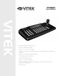
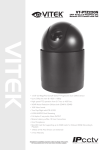
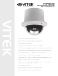
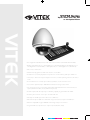
VT-PTZ Series
Xpress Dome with 18x, 26x
or 36x Optical Zoom
VITEK
• True Night Shot (D/N) Function with Automatic Cut Filter (VT-PTZ26 & VT-PTZ36)
• Built-in 36x Optical Zoom / 12x Digital Zoom (VT-PTZ36), Built-in 26x Optical Zoom /
12x Digital Zoom (VT-PTZ26) or 18x Optical Zoom / 12x Digital Zoom (VT-PTZ18)
• Auto Protocol Detection
• 248 Presets programmed with view direction, zoom, BLC.
• 4 Patterns record and play back user preference of surveillance path up to 240° sec.
• 16 Scans, 1 Auto Pan: 8 speed steps from slow to medium panning with smooth Vector
Scan.
• 8 Tours: Each tour consists up to 64 Preset, Pattern, Scan and other Tours.
• Tour can be expanded up to 500 different functions using nested Tours.
• Smooth Vector Scan mode and programmable Individual dwell time camera functions.
(Speed, Dwell time BLC, Focus, IRIS of the preset)
• 8 Alarm inputs with 0~8 priority / 2 Auxiliary outputs programmable NC & NO.
• 8 Privacy Zones: Video off or up to 8 masked blocks
• 64 steps of variable speed from 0.1°/sec to 90°/sec.
• Max manual speed 360°/sec with Turbo key pressed, Preset speed is 380°/sec.
• Minimum adjustable angle is 0.0375° with Single Step move function.
• Programmable user preferences of speed (Slow, Medium, Fast)
CYAN
MAGENTA
YELLOW
BLACK
VT-PTZ Series
CONTENTS VERIFICATION
Prior to installation of the Xpress Series Dome camera, please verify that the packaging
contains the following contents:
1.
2.
3.
4.
5.
6.
7.
8.
One Xpress Dome.
One Bubble Ring
One Instruction Manual.
Three Mounting Screws.
Three Plastic Anchors.
One Three-Pin Connector.
One Four-Pin Connector.
Two Eight-Pin Cable Assemblies.
If any of the contents are missing, please contact the Vitek Customer Help Desk
immediately.
1
VT-PTZ Series
RISK OF ELECTRICK SHOCK WARNING
WARNING
TO REDUCE THE RISK OF FIRE OR ELECTRIC SHOCK, DO NOT EXPOSE THIS PRODUCT TO RAIN
OR MOISTURE. DO NOT INSERT ANY METALLIC OBJECTS THROUGH THE VENTILATION GRILLS OR
OTHER OPENINGS ON THE EQUIPMENT.
CAUTION
EXPLANATION OF GRAPHICAL SYMBOLS
The lightning flash with arrowhead symbol, within an equilateral triangle, is intended to
alert the user to the presence of uninsulated "dangerous voltage" within the product's
enclosure that may be of sufficient magnitude to constitute a risk of electric shock to
persons.
The exclamation point within an equilateral triangle is intended to alert the user to the
presence of important operating and maintenance (servicing) instruction in the literature
accompanying the product.
2
VT-PTZ Series
DISCLAIMER
•
•
•
•
While every effort has been made to ensure that the information contained in this
guide is accurate and complete, no liability can be accepted for any errors or
omissions.
Vitek Industrial Video Products, Inc. reserves the right to change the
specifications of the hardware and software described herein at any time without
prior notice.
No part of this guide may be reproduced, transmitted, transcribed, stored in a
retrieval system, or translated into any language in any form, by any means,
without prior written permission of Vitek Industrial Video Products, Inc.
Vitek makes no warranties for damages resulting from corrupted or lost data due
to a mistaken operation or malfunction of the Xpress Domes, the software,
keyboard joystick controller, personal computers, peripheral devices, or
unapproved/unsupported devices.
Trademark Acknowledgements
•
•
Xpress Dome is a trademark of Vitek Industrial Video Products, Inc.
Other names and products not mentioned above may be registered trademarks
or trademarks of their respective companies.
Copyright ©2006 Vitek Industrial Video Products, Inc. All rights reserved.
3
VT-PTZ Series
FCC NOTICE
Xpress Domes, VT-PTZ18, VT-PTZ26
These devices comply with Part 15 of the FCC Rules. Operation is subject to the
following two conditions;
1. These devices may not cause harmful interference, and
2. These devices must accept any interference received, including interference that
may cause undesired operation.
Note: This equipment has been tested and found to comply with the limits for Class B
digital devices, pursuant to Part 15 of the FCC rules. These limits are designed to
provide reasonable protection against harmful interference in a residential installation.
These equipments generate, use and can radiate radio frequency energy and, if not
installed and used in accordance with the instructions, may cause harmful interference
to radio communications. However, there is no guarantee that interference will not
occur in a particular installation. If this equipment does cause harmful interference to
radio or television reception, which can be determined by turning the equipment off and
on, the user is encouraged to try to correct the interference by on or more of the
following measures:
•
•
•
•
Reorient or relocate the receiving antenna.
Increase the separation between the equipment and receiver.
Connect the equipment into an outlet on a circuit different from that to which the
receiver is connected.
Consult the dealer or an experience radio/TV technician for help.
Do not make any changes or modifications to the equipments unless otherwise
specified in the manual. If such changes or modifications should be made, you could be
required to stop operation of the equipments.
Vitek Industrial Video Products, Inc.
28492 Constellation Road
Valencia, CA 91355
Phone: (888) VITEK-70 / (818) 771-0300
Fax: (818) 771-0400
www.vitekcctv.com | [email protected]
Canadian Radio Interference Regulations
This is a Class A apparatus complies with Canadian ICES-003.
Cet Appareil numérique de la Classe A conforme à la norme NMB-003 du Canada.
4
VT-PTZ Series
READ THIS FIRST
Test Sessions
Before you try to record important subjects, we highly recommend that you make
several test sessions to ensure that the Xpress Dome is operating and being operated
correctly. Please note that Vitek Industrial Video Products, Inc., its subsidiaries and
affiliates, and its distributors are not liable for any consequential damages arising from
any malfunction of the Xpress Dome or its accessories.
The Privacy act of 1974 (5 U.S.C. § 552a)
Please note that the Xpress Domes are intended for surveillance use and should never
be used in a manner that invades other people’s privacy or contravenes international or
domestic privacy act and its regulations. Please be advised that in certain cases the
monitoring of individuals, private properties, or commercial properties may contravene
legal rights of such individuals even if the images were recorded for personal use.
Warranty Limitations
This equipment’s warranty is only effective in the country of sale. If a problem arises
while the Speed Dome is in use abroad, please convey it back to the country of sale
before proceeding with a warranty claim to Vitek customer help desk.
5
VT-PTZ Series
SAFETY PRECAUTIONS
z Before using the Xpress Dome, please ensure that you read and understand the
safety precautions described below. Always ensure that the Xpress Dome is
operated correctly.
z The safety precautions noted on the following pages are intended to instruct you
in the safe and correct operation of the Xpress Dome and its accessories to
prevent injuries or damage to the self, other persons and equipment.
z In this Instruction Manual, the term “Speed Dome”, “equipment” and “device”
refers primarily to the Xpress Dome and its accessories such as power supply
and its remote controller.
WARNING
z Do not cover the ventilation opening or slots on the outer casing. To prevent the
Speed Dome from overheating, provide at least two inches of air space around
the vent and the slots.
z Do not drop metallic parts through slots. This could permanently damage the
Speed Dome. Immediately turn the Speed Dome’s power off or unplug the
power cord from the power outlet. Contact a qualified service personnel
authorized by the equipment distributor or a Vitek customer help desk.
z Do not attempt to disassemble or alter any part of the equipment that is not
expressly described in this guide. Disassembly or alteration may result in high
voltage electrical shock. Internal inspections, alterations and repairs should be
conducted by qualified service personnel authorized by the equipment distributor
or Vitek customer help desk.
z Stop operating the equipment immediately if it emits smoke or noxious fumes.
Failure to do so may result in fire or electrical shock. Immediately turn the
Speed Dome’s power off, remove the power cable from the power outlet.
Confirm that smoke and fume emissions have ceased. Please consult the
Speed Dome distributor or the closest Vitek customer help desk.
z Stop operating the equipment if a heavy object is dropped or the casing is
damaged. Do not strike or shake. Failure to do so may result in fire or electrical
shock. Immediately turn the Speed Dome’s power off or unplug the power cord
from the power outlet. Please consult the Speed Dome distributor or the closest
Vitek customer help desk.
z Do not allow the equipment come into contact with, or become immersed in,
water or other liquids. Do not allow liquids to enter the interior. The Xpress
Dome has not been waterproofed. If the exterior comes into contact with liquids
or salt air, wipe it dry with a soft, absorbent cloth. In the event that the water or
other foreign substances enter the interior, immediately turn the Speed Dome’s
Power off or unplug the power cord from the power outlet. Continued use of the
equipment may result in fire or electrical shock. Please consult the Speed Dome
distributor or the closest Vitek customer help desk.
6
VT-PTZ Series
z Do not use substances containing alcohol, benzene, thinners or other flammable
substances to clean or maintain the equipment. The use of these substances
may lead to fire. Use a dry cloth on a regular periodic basis and wipe away the
dust and dirt that collects on the device. In dusty, humid or greasy environments,
the dust that collects around the ventilation or the slots on the outer casing over
long periods of time may become saturated with humidity and short-circuit,
leading to fire.
z Do not cut, damage, alter or place heavy items on the power cord. Any of these
actions may cause an electrical short circuit, which may lead to fire or electrical
shock.
z Do not handle the device or power cord if the hands are wet. Handling it with
wet hands may lead to electrical shock. When unplugging the cord, ensure that
you hold the solid portion of the plug. Pulling on the flexible portion of the cord
may damage or expose the wire and insulation, creating the potential for fires or
electrical shocks.
z Use only the recommended power accessories. Use of power sources not
expressly recommended for this equipment may lead to overheating, distortion
of the equipment, fire, electrical shock or other hazards.
7
VT-PTZ Series
CAUTION
z Avoid using, placing or storing the equipment in places subject to strong sunlight
or high temperatures, such as the greenhouse or trunk of a car. Exposure to
intense sunlight and heat may cause the battery to leak, overheat or explode,
resulting in fire, burns or other injuries. High temperatures may also cause
deformation of the casing. Ensure that there is good ventilation when using the
equipment.
z Do not store the equipment in humid or dusty areas. Storage in such areas
could lead to fire, electrical shock or other damage.
z Do not operate the Speed Dome beyond its specified temperature, humidity or
power source ratings. Do not use the Speed Dome in an extreme environment
such as in high temperature or high humidity. Use the device at temperatures
within 41°F - 104°F and humidity below 90 %. The normal operating power
source for this device is 24VDC/3amps or 24VAC/40VAC.
PREVENTING MALFUNCTION
z Avoid Strong Magnetic Fields. Never place the Speed Dome in close proximity
to electric motors or other equipment generating strong electromagnetic fields.
Exposures to strong magnetic fields may cause malfunctions or corrupt image
data.
z Avoid Condensation Related Problems. Moving the equipment rapidly between
hot and cold temperatures may cause condensation (water droplets) to form on
its external and internal surfaces. You can avoid this by placing the equipment
in an airtight, re-sealable plastic bag and letting it adjust to temperature changes
slowly before removing it from the bag.
z If Condensation forms inside the Speed Dome. Stop using the equipment
immediately if you detect condensation. Continued use may damage the
equipment. Remove the power cord from the power outlet and wait until the
moisture evaporates completely before resuming use.
8
VT-PTZ Series
TABLE OF CONTENTS
CONTENT VERIFICATION........................................................................................................ 1
RISK OF ELECTRICK SHOCK WARNING ............................................................................ 2
DISCLAIMER............................................................................................................................... 3
FCC NOTICE ................................................................................................................................ 4
READ THIS FIRST ...................................................................................................................... 5
Test Sessions....................................................................................................................... 5
The Privacy act of 1974 (5 U.S.C. § 552a) ..................................................................... 5
Warranty Limitations.......................................................................................................... 5
SAFETY PRECAUTIONS........................................................................................................... 6
WARNING.............................................................................................................................. 6
CAUTION ............................................................................................................................... 8
PREVENTING MALFUNCTION ......................................................................................... 8
I. INTRODUCTION ................................................................................................................... 13
1.1 FEATURES .................................................................................................................... 13
1.2 SYSTEM CONFIGURATION AND CONNECTION................................................ 15
II. INSTALLATION.................................................................................................................. 16
2.1 Connection Diagram...................................................................................................... 16
2.2 Termination.................................................................................................................... 16
2.3 DOME CAMERA ADDRESS (ID).............................................................................. 18
2.4 SELECTING THE PROTOCOL ................................................................................. 18
2.5 SELECTING THE COMMUNICATION SPEED ...................................................... 19
2.6 WIRE CONNECTIONS................................................................................................ 19
2.6.1 RS485/422 Connection ..................................................................................... 19
2.6.2 Alarm connection ............................................................................................... 20
2.7 MOUNTING THE SPEED DOME .............................................................................. 22
2.8 POWER ON AND BOOT UP SEQUENCE.............................................................. 23
2.9 MAIN SCREEN DISPLAY .......................................................................................... 24
III. PROGRAMMING AND OPERATION.............................................................................. 25
3.1 FUNCTION ................................................................................................................... 27
3.1.1 HOME FUNCTION............................................................................................. 27
3.1.1.1 Function..................................................................................................... 27
3.1.1.2 Number...................................................................................................... 28
3.1.1.3 Time ........................................................................................................... 28
3.1.1.4 Operation .................................................................................................. 28
3.1.1.5 Save and Exit ........................................................................................... 28
3.1.2 PRESET .............................................................................................................. 29
3.1.2.1 Programming a preset position. ............................................................ 29
3.1.2.2 Alternate method of programming a preset position.......................... 30
3.1.2.3 Deleting a programmed preset position............................................... 31
3.1.2.5 Previous / Next Page .............................................................................. 32
3.1.2.6 Save and Exit ........................................................................................... 32
3.1.3 PATTERN ........................................................................................................... 32
3.1.3.1 Programming a pattern........................................................................... 33
3.1.3.2 Alternate method of programming a pattern. ...................................... 34
9
VT-PTZ Series
3.1.3.3 Deleting a programmed pattern. ........................................................... 35
3.1.3.4 Save and Exit ........................................................................................... 35
3.1.4 SCAN (VECTOR SCAN). ................................................................................. 36
3.1.4.1 Programming a SCAN. ........................................................................... 36
3.1.4.2 Alternate method of programming a scan. .......................................... 38
3.1.4.3 Direction. ................................................................................................... 39
3.1.4.4 Swap.......................................................................................................... 39
3.1.4.5 Save and Exit ........................................................................................... 39
3.1.5 TOUR ................................................................................................................... 40
3.1.5.1 Programming a Tour with Preset Programs........................................ 41
3.1.5.2 Programming a Tour with Pattern Programs. ..................................... 42
3.1.5.3 Programming a Tour with Scan Programs. ......................................... 43
3.1.5.4 Combining PRESET, PATTERN, SCAN and TOUR. ........................ 45
3.1.5.5 Deleting a function................................................................................... 45
3.1.5.6 Previous / Next Page. ............................................................................. 46
3.1.5.7 Save and Exit ........................................................................................... 46
3.2 ALARM ......................................................................................................................... 47
3.2.1 PROGRAMMING THE ALARM ...................................................................... 47
3.2.2 SAVE AND EXIT................................................................................................ 49
3.2.3 DELETING AN ALARM.................................................................................... 49
3.2.4 SAMPLE SCENARIO ....................................................................................... 50
3.3 SCREEN ....................................................................................................................... 51
3.3.1 LANGUAGE ....................................................................................................... 51
3.3.2 PRIVACY ZONE ................................................................................................ 51
3.3.2.1 Programming a privacy zone. ................................................................ 52
3.3.2.2 Alternate method of programming a privacy zone. ............................ 53
3.3.2.3 Privacy zones displayed on screen per type....................................... 54
3.3.2.4 Deleting a privacy zone. ......................................................................... 54
3.3.2.5 Save and Exit. .......................................................................................... 55
3.3.3 NORTH DIRECTION ......................................................................................... 55
3.3.3.1 Display On / Off........................................................................................ 56
3.3.3.2 Position...................................................................................................... 56
3.3.3.3 Save and Exit ........................................................................................... 57
3.3.4 ZONE TITLE ....................................................................................................... 57
3.3.4.1 Zone Title Display ON / OFF. ................................................................ 57
3.3.4.2 Programming a zone title. ...................................................................... 57
3.3.4.3 Alternate method of programming a zone title.................................... 59
3.3.4.4 Previous / Next Page .............................................................................. 61
3.3.4.5 Save and Exit ........................................................................................... 61
3.3.4 CAMERA TITLE................................................................................................. 61
3.3.4.1 Title ............................................................................................................ 61
3.3.4.2 Display....................................................................................................... 62
3.3.4.3 Position...................................................................................................... 62
3.3.4.4 Save and Exit ........................................................................................... 62
3.4 CAMERA ...................................................................................................................... 63
3.4.1 FOCUS CONTROL ........................................................................................... 63
10
VT-PTZ Series
3.4.1.1 Mode .......................................................................................................... 63
3.4.1.2 AF Sensitivity (Automatic Focus Sensitivity) ....................................... 64
3.4.2 WB CONTROL (WHITE BALANCE CONTROL)......................................... 64
3.4.2.1 Mode .......................................................................................................... 64
3.4.2.2 R Gain (Red Gain)................................................................................... 65
3.4.2.3 B Gain (Blue Gain) .................................................................................. 65
3.4.2.4 Exit ............................................................................................................. 65
3.4.3 AE CONTROL (AUTOMATIC EXPOSURE CONTROL)............................ 65
3.4.3.1 Mode .......................................................................................................... 66
3.4.3.2 Slow Shutter ............................................................................................. 66
3.4.3.3 Iris............................................................................................................... 66
3.4.3.4 Gain ........................................................................................................... 66
3.4.3.5 Brightness ................................................................................................. 67
3.4.3.6 Shutter ....................................................................................................... 67
3.4.3.7 Exit ............................................................................................................. 67
3.4.4 LINE LOCK CONTROL .................................................................................... 67
3.4.4.1 Mode .......................................................................................................... 68
3.4.4.2 Phase......................................................................................................... 68
3.4.5 BACK LIGHT COMPENSATION.................................................................... 68
3.4.6 SHARPNESS CONTROL................................................................................. 69
3.4.7 DIGITAL ZOOM ................................................................................................. 69
3.4.8 NIGHT SHOT (VT-PTZ26 ONLY) ................................................................... 69
3.4.8.1 Mode .......................................................................................................... 70
3.4.8.2 Local Control ............................................................................................ 70
3.4.9 CAMERA DEFAULT ......................................................................................... 70
3.4.10 SAVE AND EXIT ............................................................................................. 70
3.5 SETUP ........................................................................................................................... 71
3.5.1 STABILIZER (VT-PTZ26 ONLY) .................................................................... 71
3.5.2 FLIP...................................................................................................................... 71
3.5.3 SPEED................................................................................................................. 72
3.5.4 PANNING RANGE ............................................................................................ 72
3.5.4.1 Programming Panning Range ............................................................... 72
3.5.4.2 Alternate method of programming Pan Range Limit.......................... 74
3.5.4.3 Save and Exit ........................................................................................... 76
3.5.5 TILT OVER ANGLE .......................................................................................... 76
3.5.5.1 W/O Bubble .............................................................................................. 76
3.5.5.2 On............................................................................................................... 77
3.5.5.3 With Bubble .............................................................................................. 77
3.5.6 CALIBRATION................................................................................................... 77
3.5.6.1 Origin Reset.............................................................................................. 78
3.5.6.2 Origin Position Move ............................................................................... 78
3.5.6.3 Origin Offset ............................................................................................. 79
3.5.6.4 Auto Calibration ....................................................................................... 79
3.5.6.5 Save and Exit ........................................................................................... 80
3.5.7 FACTORY DEFAULT ....................................................................................... 80
3.5.8 ERASE DATA .................................................................................................... 80
11
VT-PTZ Series
3.5.9 SYSTEM INFORMATION................................................................................. 81
3.5.10 EXIT ................................................................................................................... 81
V. GLOSSARY ........................................................................................................................... 83
VI. FUNCTION SHORTCUTS.................................................................................................. 86
12
VT-PTZ Series
I. INTRODUCTION
1.1 FEATURES
The Xpress Dome features a high resolution Exview HAD** CCD imager for enhanced
lowlight sensitivity. User friendly, on-screen pull-down menus and short-cuts make it
easy to setup and program functions.
System information aides trouble shooting by displaying the hardware and software
version of the dome driver, baud rate, and protocol.
Mechanism
Built-in 18 (VT-PTZ18) and 26 (VT-PTZ26) times optical power zoom camera
and 12 times digital zoom.
True Night Shot function with ExView HAD** and IR cut filter removal mechanism
(VT-PTZ26 only).
Functions
248 Presets programmed with view direction, zoom, BLC.
4 Patterns record and play back user preference of surveillance path up to 240
sec.
16 Scans: 8 speed steps from slow to medium panning with smooth Vector
Scan.
1 Auto Pan: Continuous 360 degrees pan with manual tilt and zoom.
8 Tours: Each tour consists up to 64 Preset, Pattern, Scan and other Tours.
Tour can be expanded up to 500 different functions using nested Tours.
Smooth Vector Scan mode and programmable Individual dwell time camera
functions. (Speed, Dwell time BLC, Focus, IRIS of the preset)
8 Alarm inputs with 0~8 priority / 2 Auxiliary outputs programmable NC & NO.
8 Privacy Zones: Video off or up to 8 masked blocks
13
VT-PTZ Series
Movement
64 steps of variable speed from 0.1°/sec to 90°/sec.
Max manual speed 360°/sec with Turbo key pressed, Preset speed is 380°/sec.
Minimum adjustable angle is 0.0375° with SingleStep move function.
Programmable user preferences of speed (Slow, Medium, Fast).
Connection
Addressable up to 999 camera IDs (Extendable up to 3999 in factory mode).
Built-in RS-485/422 receiver driver.
On-site software upgrade and upload/download of programmed data into the
Xpress Series Keyboard (VT-KBD1) and Xpress Domes.
Convenience
Built-in power-line surge protection and lightning protection.
Capable of fail-safe Hot Swap.
Optional Tinted Bubble, Indoor & Outdoor pendant housing with heater & blower,
Indoor Flush Mount, Parapet mount & Roof Top mount.
14
VT-PTZ Series
1.2 SYSTEM CONFIGURATION AND CONNECTION
Additional joystick keyboard controllers such as the Xpress Keyboard (VT-KBD1) and a
variety of external switching devices such as the Saga Series Digital Video Recorders
(VT-ST and VT-XL) may be incorporated to accommodate the needs from the small to
large surveillance/security system. Figure 1 illustrates a small sample installation.
Figure 1 – Sample System Configuration
15
VT-PTZ Series
II. INSTALLATION
2.1 Connection Diagram
The base of the Xpress Dome
RS-485/422 Input:
Connect to RX+ / RX-
Alarm Interface B
Alarm Interface A
Termination Switches
24VAC 40VA or
24VDC 2Amp Input
Power Connection
Address Selection Switches
Power Switch
Protocol Selection Switches
Baud Rate Selection
2.2 Termination
Any device that is at the end of the daisy chain must be terminated. On the Speed Dome, the
dip switches can be switched to “on” position to terminate a line of communication. On other
devices such as a DVR, an appropriate termination must be set by either dip switches or
jumpers to prevent any communication errors.
16
VT-PTZ Series
The following diagram displays the dip switch settings for termination.
SW1
Terminated
Not terminated
1
ON
OFF
2
ON
OFF
The following diagrams are some sample examples of Termination configuration.
S1:Dome1 port Termination ON
DVR Termination ON
SW1:Termination ON
SW1:Termination ON
S1:Dome1 port Termination ON
DVR Termination ON
SW1:Termination ON
SW1:Termination ON
SW1:Termination ON
SW1:Termination ON
S1:Dome1 port Termination ON
S4:DVR port Termination ON
DVR Termination ON
DVR Termination ON
SW1:Termination ON
S3:Dome2 port Termination ON
SW1:Termination ON
17
TERMINATION ON
S1:Dome1 port Termination ON
SW!:Termination ON
SW1:Termination ON
SW1:Termination ON
VT-PTZ Series
2.3 DOME CAMERA ADDRESS (ID)
All devices connected in the chain must possess a unique address. If any of the
devices possess the same address, then an electrical short may occur, thus damaging
the control circuit and attached devices. Please be especially careful when installing
multiple Speed Domes with a DVR, as it is critical that the address match the channel
number of the DVR.
For example, for DVR’s channel 1 (BNC connector 1), the Speed Dome’s ID must also
be 1, for DVR’s channel 2, the Speed Dome’s ID must be 2, and so on.
If more than 16 dome cameras are installed using two or more DVRs, the following
formula is useful to determine the Dome ID: ID =16x(n-1)+m ( where n= number of
DVR, m=Camera Port)
Please refer to the following diagram to select Speed Dome address (ID).
S2
S1
8
2
7
3
8
2
7
3
8
2
7
3
9
0
1
9
0
1
9
0
1
S6
S5
on
6
5
4
6
5
4
6
5
4
S4
on
S3
DOME ID
1
251
999
S1
1
1
9
S2
0
5
9
S3
0
2
9
on
2.4 SELECTING THE PROTOCOL
The Xpress Dome can automatically negotiate with multiple protocols if the
communication speed is matched to the controlling device. Any protocol that has
already been added onto the Xpress Dome will be automatically detected and matched
with the controlling device.
Please refer to the following chart for a full list of compatible protocols.
18
VT-PTZ Series
Protocol
Dip Switches (S5)
2
3
1
Automatic Protocol Detection
EZ, S2/E, PL, ER, PH (Even Parity)
EZ, S2/E, PL, ER, PH (Odd Parity)
EZ
S2/E
PD
VN
SN
DC
KL
PS
SE
ST
VL
DI
Off
On
Off
On
Off
On
Off
On
Off
On
Off
On
Off
On
Off
Off
Off
On
On
Off
Off
On
On
Off
Off
On
On
Off
Off
On
4
Off
Off
Off
Off
On
On
On
On
Off
Off
Off
Off
On
On
On
Off
Off
Off
Off
Off
Off
Off
Off
On
On
On
On
On
On
On
2.5 SELECTING THE COMMUNICATION SPEED
Dip Switches (S6)
1
2
3
Baud Rate
2400
4800
9600
19200
38400
Off
Off
Off
Off
On
Off
Off
On
On
Off
Off
On
Off
On
Off
2.5 WIRE CONNECTIONS
2.6.1 RS485/422 Connection
The Speed Dome has a built-in RS-485/422 connection so that remote control via a
Keyboard Controller or a DVR is possible.
19
VT-PTZ Series
RS-485
① Connect the wires to the TX+/TX- ports on the control device.
② Connect to the RX+/RX- ports on the Speed Dome.
RS-422
① Switch the RS-422 setting to “On” on the dip switch S4.
② Connect the wires to the TX+/TX- and RX+/RX- ports on the control device.
③ Connect the TX+/TX- wires from the control device to the RX+/RX- and the RX+/RXwires to the TX+/TX- ports respectively.
STAR
A “Star” connection (as compared to the “Daisy Chain” connection) requires a splitter as
the RS-485 native connection does not support a “Star” connection layout.
Distance
The maximum distance for the RS-485 connection is 1.2 Km. Any distance exceeding
1.2Km requires a repeater.
2.6.2 Alarm connection
A variety of external sensors such as Magnetic contacts, PIR (motion detectors) and
other circuits can be used in conjunction with the alarm input/output of the Speed Dome
to various triggers.
Please refer the following charts when connecting the alarm wires.
Alarm A
Alarm B
J2
ALARM A
COLOR
1
2
3
4
5
6
COM A
NC A
NO A
GND
ALARM 4
ALARM 3
BLACK
BROWN
RED
ORANGE
YELLOW
GREEN
20
VT-PTZ Series
7
8
ALARM 2
ALARM 1
BLUE
WHITE
J4
ALARM B
COLOR
1
2
3
4
5
6
7
8
COM B
NC B
NO B
GND
ALARM 8
ALARM 7
ALARM 6
ALARM 5
BLACK/WHITE
RED/WHITE
YELLOW/WHITE
GREEN/WHITE
BLUE/WHITe
PURPLE
GREY
WHITE
1. COM A / COM B
Connect the wire for the alarm output with either COM A or COM B, whether NC or
NO circuits are used.
2. NC A / NC B
Connect the wire for the alarm output using the normally closed circuit. The Speed
Dome can trigger an alarm output using a normally closed circuit to activate a variety
of external devices such as sirens, buzzers or lights.
3. NO A / NO B
Connect the wire for the alarm output using the normally open circuit.
4. GND
All the ground connections to either alarm input or output must be connected to GND.
21
VT-PTZ Series
5. Alarm 1 ~ 8
Connect the wire to the appropriate alarm input. Up to eight alarm wires can be
connected.
2.7 MOUNTING THE SPEED DOME
Once all the dip switches and all the wiring have been properly configured, the Speed
dome can be mounted in a variety of configuration using the available accessories.
The (product name here) itself should be mounted on a surface with a supporting load
of 5kg (11lbs). More weight load should be put into consideration when using
accessories.
Ceiling mount illustration
22
VT-PTZ Series
2.8 POWER ON AND BOOT UP SEQUENCE
When the Speed Dome is twisted in and locked onto the base module, it will be
powered on and will run its self diagnostic boot up sequence. It will run a series of self
tests on the RAM, pan and tilt and their point of origins.
23
VT-PTZ Series
If any of the diagnostic sequence is disturbed or is malfunctioning, then an error
message will appear to the specific function.
2.9 MAIN SCREEN DISPLAY
Compass Direction
Program No.
Function Title
Information
Dome Camera
Title
Alarm Display
Pan & Tilt Angle
Dome Camera ID
24
VT-PTZ Series
III. PROGRAMMING AND OPERATION
Provided that all connections are properly made, the Speed Dome which needs to be
programmed must be selected before any programming is done.
Please note that the Xpress Keyboard (VT-KBD1) is required to program the
Xpress Dome. All instructions below refer to the operation of the Xpress
Keyboard.
Press the number for the camera, and then press the CAM button sequentially to select
a specific camera. For example, pressing 4 then CAM will select Speed Dome number
4. Pressing 3, 8, and then CAM will select Speed Dome number 38.
Once the desired Speed Dome has been selected, press the Menu button on the
keyboard controller to access the main menu of the Speed Dome. Five submenus are
available: FUNCTION, ALARM, SCREEN, CAMERA and SETUP. The following is
the basic of joystick movements and key combinations to navigate in the programming
menu.
25
VT-PTZ Series
Button or Joystick movement in
Menu
Function
1. Go into submenus
2. Execute a command
LEFT OR RIGHT
3. Change Values
4. Navigate through menu items
UP OR DOWN
DOWN
Navigate through menu items
Complete Title editing
1. Change Value
TWIST LEFT OR RIGHT
2. Enter Title Edit mode
SHIFT + JOYSTICK MOVEMENT
ESC
HOME OR OFF BUTTON
PTZ Control Mode
Exit without making changes
Delete Value or Name of a Field.
26
VT-PTZ Series
3.1 FUNCTION
FUNCTION menu consists of the main key functions of the Xpress Dome, where the
HOME FUNCTION, PRESET, PATTER, SCAN and TOUR are configured.
3.1.1 HOME FUNCTION
HOME FUNCTION is a feature where the Xpress Dome resumes automatically its
programmed function after it has been idle for a specified time. For example, if
someone interrupts any of the programmed function, then the Xpress Dome will resume
and run the selected program after a period of time.
3.1.1.1 Function
Select the desired function to be run when left
unattended for a period of time. Select from PRESET,
PATTERN, SCAN and TOUR.
The default function is TOUR.
27
VT-PTZ Series
3.1.1.2 Number
Select the number of the programmed function to be
run.
3.1.1.3 Time
Select from 10 seconds to 240 seconds after which
the Xpress Dome resumes its programmed function.
The default is 60 seconds.
3.1.1.4 Operation
Enable or Disable the HOME FUNCTION.
3.1.1.5 Save and Exit
Save the changes and exits to the main FUNCTION
menu.
28
VT-PTZ Series
3.1.2 PRESET
PRESET supports up to 248 PAN, TILT, ZOOM, FOCUS and IRIS positions and
settings. Once programmed, the preset points can be recalled from the keyboard
controller using a combination of number keys and the PRESET button. Moreover, the
preset points can be assigned to alarm actions, as HOME function, or be programmed
into the TOUR.
Note: The PRESET menu can be accessed directly from the main screen by pressing
the PRESET button.
There are 31 pages of preset programming window. Each page holds eight presets. To
move between the pages, highlight the PREV/NEXT and then move the joystick to the
right or to the left to scroll through the available pages.
3.1.2.1 Programming a preset position.
1) Select an empty preset number.
2) Twist the joystick to activate the
programming window. “Select Position”
will start flashing.
29
VT-PTZ Series
3) Move the joystick around to select the
desired pan, tilt and zoom position.
4) Press the FOCUS button to program the
selected location. Please note that the
F (Focus), I (Iris) and B (Back Light
Compensation)
are
automatically
entered as A (Automatic), A, and F (Off)
respectively.
5) The FOCUS, IRIS and BLC can be
adjusted manually as needed. Move
the joystick to highlight the desired
function, and then twist the joystick to
toggle between A and M (Manual) for
FOCUS and IRIS, O (On) and F for BLC.
6) The TITLE is entered automatically as
PRESET. Move the joystick to highlight
the TITLE, and twist the joystick to
select
the
desired
alphanumeric
character. When the desired TITLE is
entered, move the joystick up or down.
Up to 16 alphanumeric characters can
be entered.
3.1.2.2 Alternate method of programming a preset position.
1) Select an empty preset number.
30
VT-PTZ Series
2) Press and hold down the SHIFT button
and the “Select Position” will start
flashing.
3) Do not let go of the SHIFT button, and
move the joystick around to select the
desired pan, tilt and zoom position.
4) Let go of the SHIFT button to finish
programming the preset position.
3.1.2.3 Deleting a programmed preset position.
1) Move the joystick to highlight the
desired preset number.
2) Press the OFF button to delete the
selected preset position.
31
VT-PTZ Series
3.1.2.5 Previous / Next Page
Highlight and move the joystick left or right to switch
between the 31 pages of preset pages. There are a
total of 248 preset positions available.
3.1.2.6 Save and Exit
Save the changes and exits to the main FUNCTION
menu.
3.1.3 PATTERN
PATTERN memorizes the movement controlled by user and duplicates the movement.
The movement can be any combination of PAN, TILT and ZOOM coordinates. Up to
four separate patterns can be memorized, for a maximum of 240 seconds combined.
Note: The PATTERN menu can be accessed directly from the main screen by pressing
the PATTERN button.
32
VT-PTZ Series
3.1.3.1 Programming a pattern.
1) Select an empty pattern number.
2) Twist the joystick to activate the
programming window. “Select Position”
will start flashing. Please note that the
second has starts counting as soon as
the program window is entered.
3) Move the joystick around and zoom in
and out to create the path of the pattern.
4) Press FOCUS button to program the
path. Please note the duration of the
pattern, and the total duration of the
pattern.
5) The TITLE is can be modified before or
after programming the pattern. Move
the joystick to highlight the TITLE, and
twist the joystick to select the desired
alphanumeric character.
When the
desired TITLE is entered, move the
joystick up or down.
Up to 16
alphanumeric characters can be entered.
33
VT-PTZ Series
3.1.3.2 Alternate method of programming a pattern.
1) Select an empty pattern number.
2) Press and hold down the SHIFT button
and the “Select Position” will start
flashing.
3) Do not let go of the SHIFT button, and
move the joystick and zoom in and out
to create the path of the pattern.
4) Let go of the SHIFT button to finish
programming the pattern.
34
VT-PTZ Series
3.1.3.3 Deleting a programmed pattern.
1) Move the joystick to highlight the
desired pattern number.
2) Press the OFF button to delete the
selected preset position.
3.1.3.4 Save and Exit
Save the changes and exits to the main FUNCTION
menu.
Note: If the total programming time reaches 240 seconds, it will automatically
interrupt the programming for a short moment, and the start programming again.
Previous data will be overwritten.
35
VT-PTZ Series
3.1.4 SCAN (VECTOR SCAN).
SCAN supports up to 16 programmed sections of angles at eight programmable speeds,
also known as “Vector Scan”. “Vector Scan” shows a moving path from a starting point
to an end point while panning, tilting and zooming simultaneously. In other words, the
Xpress Dome is capable of moving the three coordinates while moving from one point to
another.
Note: The SCAN menu can be accessed directly from the main screen by pressing the
SCAN button.
3.1.4.1 Programming a SCAN.
1) Select a scan number by moving the
joystick to the left or right.
2) The title is entered automatically as
AUTOSCAN01 through AUTOSCAN16.
Twist the joystick to enter the desired
title. Move the joystick up or down to
save the title. Up to 16 alphanumeric
characters can be entered.
36
VT-PTZ Series
3) Select the speed of the scan. Available
speeds are: 1 through 8 (8 being the
fastest), Slow and Medium. The Default
speed is 3.
4) Highlight START, and then twist the
joystick and move the joystick to select
the desired pan, tilt and zoom position.
This will be the starting point of the
SCAN.
5) Press the FOCUS button to program the
selected location.
6) Highlight END, and then twist the
joystick and move the joystick to select
the desired pan, tilt and zoom position.
This will be the ending point of the
SCAN.
7) Press FOCUS button to program the
selected location.
37
VT-PTZ Series
3.1.4.2 Alternate method of programming a scan.
1) Highlight START, and then press and
hold the SHIFT button.
2) Do not let go of the SHIFT button, and
move the joystick around to select the
desired pan, tilt and zoom position
3) When the desired location is selected,
let go of the SHIFT button to finish
programming the starting point.
4) Highlight END, and then press and hold
the SHIFT button.
5) Do not let go of the SHIFT button, and
move the joystick around to select the
desired pan, tilt and zoom position.
38
VT-PTZ Series
6) When the desired location is selected,
let go of the SHIFT button to finish
programming the end point.
3.1.4.3 Direction.
Select the direction of the scan. Available options are
CW (Clockwise) and CCW (Counter Clockwise). The
default is CCW.
3.1.4.4 Swap.
Swap exchanges the START and the END point of
the scan. The default is OFF.
3.1.4.5 Save and Exit
Save the changes and exits to the main FUNCTION
menu.
39
VT-PTZ Series
3.1.5 TOUR
There are eight programmable Tours. Each tour consists of up to eight preset
positions, patterns, scans or other tours. The tours that are included in a tour are
called second-level tours, which itself can be expanded to over 56 functions in a single
tour. However, the second-level tours will be ignored when recalled by another tour.
Please refer to the following example for better understanding.
Tour settings:
Tour 01:
Tour 02:
Tour 03:
Tour 04:
Preset 02, Preset 03, Tour 02, Tour 03
Preset 05, Preset 06, Tour 04, Preset 05
Preset 07, Pattern 01
Preset 08, Preset 05, Pattern 01
Example 1
Tour 01 will run as follow when executed:
Preset 02 Î Preset 03 Î Preset 05 Î Preset 06 ÎPreset 05 ÎPreset 07 Î
Pattern 01, and then repeated.
Please note that Tour 04 which is part of Tour 02 will be skipped as it is being recalled
as part of Tour 01.
Example 2
Tour 02 will run as follow when executed:
Preset 05 Î Preset 06 Î Preset 08 Î Preset 05 Î Pattern 01 and then repeated.
As Tour 04 does not include any other tours to be recalled, Tour 02 will successfully
include Tour 04 as part of its normal Tour.
40
VT-PTZ Series
3.1.5.1 Programming a Tour with Preset Programs.
1) Select the Tour by moving the joystick
left or right.
2) Twist the joystick to customize the
Tour title.
3) Select an empty location.
4) Press the PRESET button.
5) When the PRESET button is pressed,
the
first
program
is
entered
automatically. Move the joystick to the
right and press the PRESET button to
view the programmed position. The
program number can be changed by
twisting the joystick.
41
VT-PTZ Series
6) Select from the three available
speeds, F (Fast), M (Medium) and S
(Slow) for the camera movement.
The default is F.
7) Select the dwell time for the PRESET
to stay at the programmed location.
The default is 3 seconds. Available
dwell time is from 1 to 99 seconds.
8) Repeat steps 3 through 7 for additional PRESET programs to be run. Please
note that the preset programs must be preprogrammed before they can be
included in the TOUR.
3.1.5.2 Programming a Tour with Pattern Programs.
1) Select an empty location.
2) Press the PATTERN button. When
the PATTERN button is pressed, the
first program is entered automatically.
42
VT-PTZ Series
3) Move the joystick to the right and twist
the joystick to select the pattern
program.
4) Select from the three available
speeds, F (Fast), M (Medium) and S
(Slow) for the camera to move to the
beginning of the pattern. The default
is F.
5) Select the dwell time for the camera
to stay at the view after the pattern
program has run. The default is 3
seconds. Available dwell time is from
1 to 99 seconds.
6) Repeat steps 1 through 5 for additional PATTERN programs to be run. Please
note that the pattern programs must be preprogrammed before they can be
included in the TOUR.
3.1.5.3 Programming a Tour with Scan Programs.
1) Select an empty location.
43
VT-PTZ Series
2) Press the SCAN button. When the
SCAN button is pressed, the first
program is entered automatically.
3) Move the joystick to the right and twist
the joystick to select the scan
program.
4) Select from the three available
speeds, F (Fast), M (Medium) and S
(Slow) for the camera to move to the
beginning of the scan. The default is
F.
5) Select the dwell time for the camera
to stay at the view after the scan
program has run. The default is 3
seconds. Available dwell time is from
1 to 99 seconds.
6) Repeat steps 1 through 5 for additional scan programs to be run. Please note
that the scan programs must be preprogrammed before they can be included in
the TOUR.
44
VT-PTZ Series
3.1.5.4 Combining PRESET, PATTERN, SCAN and TOUR.
1) Using the process to enter the preset,
patter and scan, any of the functions
can be combined in a tour and can be
run together. The example to the left
shows Tour 1 which includes five preset
programs, one scan program and one
pattern program to be run sequentially.
2) The example to the left shows Tour 2
which includes a combination of preset
programs, one pattern and Tour 1 to be
run sequentially. Please note that all of
the functions from Tour 1 will be run as
part of Tour 2.
3.1.5.5 Deleting a function.
1) Move the joystick to highlight a desired
function.
2) Press the OFF button to delete the
selected function.
45
VT-PTZ Series
3.1.5.6 Previous / Next Page.
Highlight and move the joystick left or right to switch
between the eight available pages per tour, for a total
of 64 functions within a tour.
3.1.5.7 Save and Exit
Save the changes and exits to the main FUNCTION
menu.
46
VT-PTZ Series
3.2 ALARM
ALARM menu configures the eight alarm inputs and two alarm outputs. The alarm
inputs can be programmed to work in conjunction with any of the four functions,
PRESET, PATTERN, SCAN AND TOUR to respond immediately and send the
camera’s view to the designated area.
3.2.1 PROGRAMMING THE ALARM
1) Highlight an alarm number by moving
the joystick up or down.
2) Highlight the FUNCTION and twist the
joystick to select the PRESET program
to be executed when the alarm triggers.
PATTERN, SCAN and TOUR can only
be selected by pressing the appropriate
button when the priority level is set to 0.
47
VT-PTZ Series
3) Select the priority of the function. There
are nine levels of priority. There is only
one level 0 which overrides any other
levels of priority. Level 1 through 8 can
be duplicated for the rest of the alarms.
4) Select the type of the alarm input circuit.
Available options are NC (Normally
Closed), NO (Normally Open) and OFF.
The default is OFF.
5) Select the alarm output.
Available
options are R01 (Relay 01), R02 (Relay
02) and OFF.
6) Select the amount of seconds to which
the alarm will be active after the initial
trigger. Available time frame is from 1
second to 99 seconds. The default hold
time is 1 second.
7) Select ON to show all alarms including
past alarms, or OFF to show activated
alarms only. The default is OFF.
48
VT-PTZ Series
3.2.2 SAVE AND EXIT
Save the changes and exits to the main FUNCTION
menu.
3.2.3 DELETING AN ALARM
1) Move the joystick to highlight the
desired alarm.
2) Press the OFF button to delete the
selected alarm.
49
VT-PTZ Series
3.2.4 SAMPLE SCENARIO
As the priority and the functions settings may be confusing, please refer to the following
sample scenario for a better understanding.
In this scenario, let’s assume that alarms 1 through 6
are triggered simultaneously.
Alarm 1 is set to priority level 0 which will execute
Autoscan 1 titled as “Example001” when the Normally
Closed Circuit is broken.
As priority level 0 supersedes all other alarms,
Autoscan 1 will be executed before any other
functions listed with other alarms, and at the same
time, the relay 1 will be triggered.
When the alarm 1 is released after 10 seconds, alarm
2 and 3 will call PRESET 1 and PRESET 2 and relay
2 will be triggered.
Alarm 2 and 3 will alternate between the two preset
programs as long as the alarms remain active.
Alarms 4 through 6 are ignored until alarm 2 and 3
are released.
50
VT-PTZ Series
3.3 SCREEN
SCREEN menu consists of the screen related features, where the LANGUAGE,
PRIVACY ZONE, NORTH DIRECTION, ZONE TITLE, and CAMERA TITLE are
configured.
3.3.1 LANGUAGE
The only available language supported at this time is English.
3.3.2 PRIVACY ZONE
51
VT-PTZ Series
Privacy zones offers up to eight independent areas that can be either masked off or
have the camera’s view off to prevent viewing of restricted or unwanted areas.
3.3.2.1 Programming a privacy zone.
1) Highlight a privacy zone number and
twist the joystick to enter the
programming window. “Select Position”
will start flashing.
2) Move the joystick around to select the
desired pan, tilt and zoom position.
What is shown on the screen is what will
be masked off. Please note that the
farther the camera is zoomed in, the
smaller the mask will become.
3) Press the FOCUS button to program the
selected location.
4) Move the joystick to highlight the title of
the privacy zone.
52
VT-PTZ Series
5) Twist the joystick to enter up to 16
alphanumeric characters.
6) Select the privacy zone to be ON or
OFF.
7) Select from the two types of the privacy
zones, MASK or V. OFF (Video OFF).
3.3.2.2 Alternate method of programming a privacy zone.
1) Highlight a privacy zone number.
2) Press and hold down the SHIFT button
and the “Select Position” will start
flashing. Do not let go of the SHIFT
button, and move the joystick around to
select the desired pan, tilt and zoom
position. What is shown on the screen
becomes the privacy zone.
53
VT-PTZ Series
3) Let go of the SHIFT button to finish
programming the preset position.
3.3.2.3 Privacy zones displayed on screen per type.
1) Privacy zone shown when using MASK
option.
2) Privacy zone shown when using V. OFF
option.
3.3.2.4 Deleting a privacy zone.
1) Highlight a desired privacy zone to
delete.
54
VT-PTZ Series
2) Press the OFF button to delete the
selected privacy zone.
3.3.2.5 Save and Exit.
Save the changes and exits to the main SCREEN
menu.
3.3.3 NORTH DIRECTION
North direction allows the user to keep track of where the direction of North is. For
example, if the Xpress Dome is installed at a location where there may be no points of
references (e.g. highway in the desert, farm lands, and etc.), it will provide a point of
reference so that the user is aware of which direction the camera is viewing.
55
VT-PTZ Series
3.3.3.1 Display On / Off
Select the North Direction display On or Off.
3.3.3.2 Position
1) Twist the joystick to enter the
programming mode. “Select Position”
will start flashing.
2) Move the joystick around to select the
new position for the north direction, and
then press the FOCUS button.
3) The new position will be displayed, and
DISPLAY will be automatically switched
to “ON”.
56
VT-PTZ Series
3.3.3.3 Save and Exit
Save the changes and exits to the main SCREEN
menu.
3.3.4 ZONE TITLE
There are a total of 24 available zone titles that can be programmed between specific
areas.
3.3.4.1 Zone Title Display ON / OFF.
Select the zone title display option on or off.
3.3.4.2 Programming a zone title.
1) Select an empty zone number and
move the joystick to START column.
57
VT-PTZ Series
2) Twist the joystick and “Select Position”
will start flashing. Move the joystick
around to select the desired pan, tilt and
zoom position.
3) Press the FOCUS button to program the
selected location.
4) Move the joystick to the END column of
the same zone number.
5) Twist the joystick and “Select Position”
will start flashing. Move the joystick
around to select the desired pan, tilt and
zoom position.
6) Press the FOCUS button to program the
selected location.
58
VT-PTZ Series
7) Move the joystick to TITLE column of
the same zone number.
8) Twist the joystick to enter up to 16
alphanumeric characters for the zone
title.
9) Move the Joystick up or down to finish
entering the title.
3.3.4.3 Alternate method of programming a zone title.
1) Select an empty zone number and
move the joystick to START column.
2) Press and hold the SHIFT button and
“Select Position” will start flashing. Do
not let go of the joystick, and it around
to select the desired pan, tilt and zoom
position.
59
VT-PTZ Series
3) Let go of the SHIFT button to finish
programming the START location of the
zone title.
4) Move the joystick to the END column of
the same zone number.
5) Press and hold the SHIFT button and
“Select Position” will start flashing. Do
not let go of the joystick, and it around
to select the desired pan, tilt and zoom
position.
6) Let go of the SHIFT button to finish
programming the zone title.
60
VT-PTZ Series
3.3.4.4 Previous / Next Page
Highlight and move the joystick left or right to switch
between the four pages of zone title pages. There
are a total of 24 zone titles available.
3.3.4.5 Save and Exit
Save the changes and exits to the main SCREEN
menu.
3.3.4 CAMERA TITLE
The Xpress Dome can be labeled using up to 16 alphanumeric characters.
3.3.4.1 Title
Twist the joystick to enter up to 16 alpha numeric
characters.
61
VT-PTZ Series
3.3.4.2 Display
Select the display mode of the camera title, ON or
OFF.
3.3.4.3 Position
Select the display mode of the X and Y coordinates of
the camera’s view.
3.3.4.4 Save and Exit
Save the changes and exits to the main SCREEN
menu.
62
VT-PTZ Series
3.4 CAMERA
CAMERA menu allows customization of the camera module installed in the Xpress
Dome. The options consist of FOCUS CONTROL, WHITE BALANCE CONTROL,
AUTOMATIC EXPOSURE CONTROL, BACK LIGHT COMPENSATION, SHARPNESS,
DIGITAL ZOOM and CAMERA DEFAULT.
3.4.1 FOCUS CONTROL
3.4.1.1 Mode
Available focus modes are AUTO and MANUAL.
When set to AUTO, the camera will automatically
adjust the focus. When set to MANUAL, the user will
have to manually adjust the focus. The default is
AUTO.
63
VT-PTZ Series
3.4.1.2 AF Sensitivity (Automatic Focus Sensitivity)
Available Automatic Focus Sensitivity modes are
LOW and HIGH.
Automatic Focus Sensitivity
determines the responsiveness of the focus
adjustment. The default is LOW.
3.4.2 WB CONTROL (WHITE BALANCE CONTROL)
WB CONTROL adjusts the white balance of the picture. As different lighting conditions
affect the picture differently, it enables the camera to automatically, or manually adjust
to different environments for optimal picture quality.
3.4.2.1 Mode
Available options are AUTO, INDOOR, OUTDOOR,
ONE PUSH, ATW and MANUAL.
*ONE PUSH White Balance mode means that the
lens will adjust the white balance on a subject when
the joystick is moved around. The white balance is
then held until the joystick moves the camera.
64
VT-PTZ Series
3.4.2.2 R Gain (Red Gain)
Adjust the Red Gain in MANUAL mode.
3.4.2.3 B Gain (Blue Gain)
Adjust the Blue Gain in MANUAL mode.
3.4.2.4 Exit
Exit from the WB CONTROL.
3.4.3 AE CONTROL (AUTOMATIC EXPOSURE CONTROL)
65
VT-PTZ Series
AE CONTROL adjusts the exposure of the lens. As different brightnesses affect the
picture differently, it enables the lens to automatically, or manually adjust to different
lighting conditions for optimal brightness.
3.4.3.1 Mode
Select the camera exposure mode. Available options
are FULL AUTO, MANUAL, IRIS PRIORITY,
SHUTTER PRIORITY, and BRIGHTNESS.
3.4.3.2 Slow Shutter
Limits the Digital Slow Shutter Speed. Available
options are ½, ¼, 1/8, 1/15, 1/30, 1/60 and Full Auto.
3.4.3.3 Iris
Adjust the Iris value to change the aperture setting.
Available options are CLOSE, F28, F22, F19, F16,
F14, F11, F9.6, F8.0, F6.8, F5.6, F4.8, F4.0, F3.4,
F2.8, F2.4, F2.0, F1.6 and F1.4.
The Iris setting can only be changed in MANUAL and
IRIS PRIORITY modes.
3.4.3.4 Gain
Adjust the picture brightness gain. Available options
are 0db through 30db.
66
VT-PTZ Series
3.4.3.5 Brightness
Adjust the brightness of the picture. Available options
are 0 through 31.
3.4.3.6 Shutter
Adjust the shutter speed of the camera.
options are 1/1 through 1/30000.
3.4.3.7 Exit
Exit to the Camera Menu.
3.4.4 LINE LOCK CONTROL
67
Available
VT-PTZ Series
Line Lock allows adjusting the picture’s phase rate with other monitors, switchers, and
cameras.
3.4.4.1 Mode
Select the mode for the phase adjustment. Select the
Internal mode to adjust the phase within the camera
module, and select the External mode to adjust with a
variety of other devices, such as monitors, switchers,
cameras and multiplexers.
3.4.4.2 Phase
Select the Phase frequency of the camera. Available
options are 0 through 255.
3.4.5 BACK LIGHT COMPENSATION
Back Light Compensation enables the objects in
the foreground with the bright background to be
clearer. The default is OFF.
68
VT-PTZ Series
3.4.6 SHARPNESS CONTROL
Control the sharpness of the picture digitally.
Available options are 0 through 63. The default
value is 9.
3.4.7 DIGITAL ZOOM
Digital Zoom further enhances the zoom ratio by
digitally magnifying the picture. Available options
are 2X, 4X and MAX (12X). The default is OFF.
3.4.8 NIGHT SHOT (VT-PTZ26 and VT-PTZ36 ONLY)
Night Shot allows adjusting the camera between the day mode and the night mode.
69
VT-PTZ Series
3.4.8.1 Mode
Select between Auto and Manual mode. The camera
will switch automatically between the day and night
modes based on the environmental changes in Auto
mode. The camera can be manually switched
between day and night modes in Manual mode.
3.4.8.2 Local Control
Manually turn on or off the Night mode. The default
setting is OFF.
3.4.9 CAMERA DEFAULT
Revert the camera settings back to factory
default.
3.4.10 SAVE AND EXIT
Save settings and exit to the MAIN MENU screen.
70
VT-PTZ Series
3.5 SETUP
Setup allows customization of the mechanics of the Xpress Dome. The options consist
of FLIP, SPEED, PANNING RANGE, TILT OVER ANGLE, CALIBRATION, FACTORY
DEFAULT, INITIALIZE DATA, ERASE DATA and SYSTEM INFORMATION.
3.5.1 STABILIZER (VT-PTZ26 ONLY)
The stabilizer digitally steadies the camera to
provide a smoother picture when the Xpress
Dome is installed in an unstable environment (e.g.
on top of a skyscraper, windy environment, and
such). The default is OFF.
3.5.2 FLIP
The Flip is a useful tool to follow an object or a
human being passing directly beneath the Xpress
Dome. For example, when the Flip option is set
to ON, the camera will move from 0 degree to 90
degrees position vertically and continue to move
to 180 degrees without interruption. The picture
will be digitally corrected at 90 degrees to provide
a reverse image, which in fact will be the normal
view for the flip side. The default is ON.
71
VT-PTZ Series
3.5.3 SPEED
Select the default speed of the camera
movement when the camera is controlled
manually. Select from Fast, Medium and Slow.
The default is FAST.
3.5.4 PANNING RANGE
The Xpress Dome’s movement of range can be restricted depending on the
environment. For example, when the Xpress Dome is installed in a corner or near a
wall, it makes sense to limit the movement of the camera so that it does not look at
where it is unnecessary.
3.5.4.1 Programming Panning Range
1) Highlight the Right Pan Limit.
72
VT-PTZ Series
2) Twist the joystick to activate the
programming window. “Select Position”
will start flashing. Move the joystick
around to select the desired pan
position.
3) Press the Focus button to program the
selected location.
4) Highlight the Left Pan Limit
5) Twist the joystick to activate the
programming window. “Select Position”
will start flashing. Move the joystick
around to select the desired pan
position.
6) Press the Focus button to program the
selected location.
73
VT-PTZ Series
7) Switch Enable to “ON” to activate the
Pan Range Limit.
8) Sometimes, the Pan Range Limit may
be the opposite of the intended limits. If
such is the case, simply highlight the
SWAP RIGHT/LEFT and twist the
joystick to swap the right and left pan
limit.
3.5.4.2 Alternate method of programming Pan Range Limit.
1) Highlight the Right Pan Limit.
2) Press and hold down the SHIFT button
and the “Select Position” will start
flashing.
74
VT-PTZ Series
3) Do not let go of the SHIFT button, and
move the joystick around to select the
desired pan position.
4) Let go of the SHIFT button to finish
programming the pan position.
5) Highlight the Left Pan Limit.
6) Press and hold down the SHIFT button
and the “Select Position” will start
flashing.
7) Do not let go of the SHIFT button, and
move the joystick around to select the
desired pan position.
75
VT-PTZ Series
8) Let go of the SHIFT button to finish
programming the pan position.
3.5.4.3 Save and Exit
Save the changes and exit to the SETUP
menu.
3.5.5 TILT OVER ANGLE
Tilt Over Angle sets the limit to the horizontal view angle so that the trim ring or the
housing or the ceiling does not obstruct the view of the camera.
3.5.5.1 W/O Bubble
This factory default setting limits the tilt range of the
Xpress Dome to 0 degrees and 180 degrees.
76
VT-PTZ Series
3.5.5.2 On
The tilt range of the Xpress Dome is limited to -5
degrees and 185 degrees. In other words, the tilt
range is above the horizon.
3.5.5.3 With Bubble
The tilt range of the Xpress Dome is limited to 10
degrees and 170 degrees. This setting is
recommended when the Xpress Dome is used in
conjunction with the flush mount housing (VTPTFMK/C) and the indoor and outdoor housings
(VT-PTHSG/C).
3.5.6 CALIBRATION
The Xpress Dome features a sensor within its mechanism to sense and retain the exact
position of each and every movement so that any programmed functions and features
are replicated without error time after time. However, even the most sophisticated
mechanism can be presented with an anomaly due to several factors: natural disasters
such as earthquakes or hurricane winds altering its point of origin, human errors (e.g.
moving the dome accidentally), or even mechanical failures that requires replacement of
the Xpress Dome. Calibration allows rectifying even the slightest changes applied to
the dome’s point of origin, which would affect all programmed functions.
77
VT-PTZ Series
3.5.6.1 Origin Reset
Origin Reset reverts the point of origin, or the point of reference back to when the
Xpress Dome was first powered on.
1) Highlight Origin Reset and move the
joystick to the right.
2) Press the ENTER or the MENU button
to confirm Origin Reset, or press the
ESC button to exit without resetting the
Origin.
3) When the ENTER button is pressed, the
Xpress Dome will reset and reinitialize
just as when the Xpress Dome was first
powered on. The point of origin will be
reset back to when the Xpress dome
was powered on.
3.5.6.2 Origin Position Move
If the Xpress Dome needs to be replaced, then the point of origin may have to be
readjusted as the point of origin will be different based on where the Xpress Dome was
positioned when first powered on. The point of origin can be offset to match the original
point of origin to avoid reprogramming the Xpress Dome.
1) Highlight Origin Position Move and twist
the joystick to enter the programming
window.
78
VT-PTZ Series
2) Move the joystick around to select the
desired point of origin.
3) Press the FOCUS button to program the
new point of origin and exit to
Calibration menu.
3.5.6.3 Origin Offset
Enable or disable the point of origin offset. The
default is DISABLE.
3.5.6.4 Auto Calibration
Constantly monitor and readjust the point of origin to
eliminate the need to reset the Xpress Dome. The
default is OFF.
79
VT-PTZ Series
3.5.6.5 Save and Exit
Save the settings and exit to the Setup menu.
3.5.7 FACTORY DEFAULT
Revert all settings back to factory default.
3.5.8 ERASE DATA
Reset all programmed functions and features back to factory default. Origin offset value
is not affected by erasing the data.
80
VT-PTZ Series
3.5.9 SYSTEM INFORMATION
Displays basic information about the Xpress Dome, including the module type,
hardware revision, firmware revision, protocol and the current baud rate.
3.5.10 EXIT
Exit to the Main Menu screen.
81
VT-PTZ Series
IV. SPECIFICATIONS
VT-PTZ18
VT-PTZ26
Image Sensor
1/4" Interline Transfer CCD
Effective Pixels
768(H) X 494(V)
Horizontal Resolution
Minimum Illumination
Lens
Angle of View
Shutter Speed
VT-PTZ36
480 TV Lines
0.7 Lux 50IRE / 0.05 Lux
(F1.4 Slow Shutter)
1.0 Lux 50IRE / 0.01 Lux
(Night mode w/ ICR on)
1.4 Lux 50IRE / 0.01 Lux
(Night mode w/ ICR on)
F1.4(f=4.1~73.8mm Optical)
18X Optical/12X Digital
F1.6(f=3.5~91mm Optical)
26X Optical/12X Digital
F1.6 (f=3.4~122.4mm
Optical) 36X Optical/12X
Digital
4.1mm-48º(H) 73.8mm-2.8
º(H)
3.8mm-54.2º(H) 91mm-2.2
º(H)
3.4mm-57.8º(H) 122.4mm1.7º(H)
NTSC - 1 ~ 1/10,000 Pal - 1~1/10,000
S/N Ratio
50dB
Video Output
1.0 Vp-p, 75 Ohm Composite
Sync System
Int/Ext, V-Phase Remote Control
Scaning System
2:1 Interface
Focus
Auto with manual override
White Balance
Auto with manual override
Iris Control
Auto with manual override
Gain Control
Auto with manual override
Pan Travel
360º Continuous
Manual Pan Speed/sec
0.1~90º/sec
Preset Pan Speed/sec
380º/sec
Tilt Travel
-5º~90º/95º
Manual Tilt Speed/sec
0.1~90º/sec
Preset Tilt Speed/sec
380º/sec
Proportional Pan & Tilt
Yes
Preset Accuracy
0.2º
Communication
RS-422/485, 8bit, 1bit stop No parity, 2.4~230Kbps
Preset
248 Position
Area title
24 Area Names
Privacy Zone
8 Blocks in a screen
Title Character
16 Character
Tour
8 Tour
Pattern
4(1 Full or 3, 240sec)
Auto Pan
16 Scan, 1 Auto Pan
Auto Flip
Digital Quick Turn
Alarm(Input/Output)
8/2
Certifications
FCC CE Class A, UL/cUL
Warranty
2 Years Limited Warranty
Power
Dimensions (OD x H)
18~30VAC/Surge Protection 24VAC/40VA or 24DC/3A
Pendant Mount: 4.96" x 7.13" / Flush Mount: 4.96" x 3.15"
82
VT-PTZ Series
V. GLOSSARY
ALARM ACTIONS
The assigned responses of the dome camera when there is input status change. The
dome may call Presets for each of the eight inputs. The dome reports the alarm states
to the Keyboard controller for processing.
AREA TITLE
It is the name of the horizontal sector from a certain start point to end point of the
selected dome. Up to 24 areas can be programmed for the dome.
AUTOMATIC GAIN CONTROL (AGC)
Allows for the amplification of the video signal in scenes with minimal ambient light.
Many low-light scenes result in picture noise. As gain is increased, the picture noise is
also amplified. When AGC is enabled, the value of the gain setting is based on
feedback from the camera. When AGC is disabled, the camera uses the value set for
the manual gain setting. The trade-off between picture level and noise may be adjusted
when AGC is disabled.
DIAGONALSCAN (VECTOR SCAN)
Move from start point to end point including tilt and zoom simultaneously and linearly.
DIGITAL SLOW SHUTTER (DSS)
DSS enhances video quality in extreme low-light situations. When the Low Shutter
setting is enabled, low-light information is collected over multiple fields based on the
Shutter Limit setting. As a result, video may appear blurred or choppy in extreme lowlight situations. This setting does not effect camera operation in normal lighting
situations. See also Automatic Gain Control (AGC).
FLIP/ DIGITAL FLIP
It allows the dome to turn 180 degrees when the camera tilts to its lower limit. When the
dome flips (rotates), the camera starts moving upward as long as the tilt control is kept
in the down position. Once the control is released, the tilt control returns to its normal
operational mode. The flip feature is useful when you need to track someone who walks
directly beneath the dome and continues on the other side.
HOME POSITION
The default position to which the dome camera returns after an assigned period of
inactivity passes. The default position may be a Preset, Tour, Pattern, or No Action.
INPUT ALARM
A connection point on the dome camera that enables the system to monitor Input
Devices. There are four inputs available for the dome camera.
83
VT-PTZ Series
INPUT DEVICES
External devices that provide information about the condition of system components
that connect to the inputs on the dome camera. Typical input devices include door
contacts, motion detectors and smoke detectors.
IR MODE
A feature of the camera that permits manual or automatic switching between color and
IR(black-and-white) operation. When IR mode is active, clearer images may be
obtained under low-light conditions.
LINE LOCK
Allows you to phase lock the video with the AC power line. When line lock is enabled, it
prevents vertical video rolling when switching multiple cameras to a single monitor. If
text appears slightly tinted on color monitors, disabling the line lock may prevent this
problem.
NORTH DIRECTION
User-definable setting that may correspond to magnetic north or some well-known
landmark.
Used to approximate the camera dome's pointing direction when Direction Indicators
are enabled.
ON-SCREEN MENU
The text overlay menu system used for setting dome features. The utility is accessed
using a
keystroke combination. The utility provides settings for camera functions, zoom, alarms,
text
display, and password protection.
PATTERN
A series of pan, tilt, zoom and focus movements from a single programmable dome. Up
to 8 patterns may be programmed for the dome camera.
PRESET
Programmed video scene, based on a specific pan, tilt, zoom, and focus settings. Up to
240 presets may be programmed for the dome camera.
PRIVACY ZONES
Masked areas of the dome camera's viewing area. These masks prevent operators of
the surveillance system from viewing these designated zones. The Privacy Zones move
in relation to the dome camera’s pan/tilt position. In addition, the apparent size of the
Privacy Zone adjusts automatically as the lens zooms in or out. Up to eight Privacy
Zones may be established for a dome camera.
SHUTTER LIMIT
Setting used to define the maximum exposure time for the Open Shutter setting. The
84
VT-PTZ Series
values for the setting range from 1/2 to 1/60. The default setting is 1/4.
WHITE BALANCE
Adjustments in the color hue (red and blue) gains for a camera so that true white
appears white in the image. It is normally compensated for by the automatic gain control.
In some lighting conditions, you may need to manually adjust the red and blue settings
for optimal viewing. When Automatic White Balance is enabled, the camera measures
the image and automatically adjusts the red and blue settings to balance white. When
Automatic White Balance is disabled, the camera uses the values set for the red and
blue settings to balance white.
85
VT-PTZ Series
VI. FUNCTION SHORTCUTS
Short Cut Key
PRST
Function
Pop up preset setup menu.
TOUR
Pop up guard Tour setup menu.
PTRN
Pop up Pattern setup menu.
SCAN
No.+ PGM +PRST
Pop up Auto Scan setup menu.
No.+ PGM +TOUR
Pop up tour setup menu at the selected number.
No.+ PGM +PTRN
Pop up pattern setup menu at the selected number.
No.+ PGM +SCAN
Pop up auto scan setup menu at the selected number.
1 ~ 4 + ON
Turn On Relay.
1 ~ 4 + OFF
Turn Off Relay.
10 + ON
Night Shot on
10 + OFF
Night Shot off
11 + ON
BLC on
11 + OFF
BLC off
12 + ON
Digital Zoom on (According to digital zoom setting)
12 + OFF
Digital Zoom off
13 + ON
Dome OSD on
13 + OFF
Dome OSD off
14 + ON
Dome Area Title Display on
14 + OFF
Dome Area Title Display off
15 + ON
View Direction on
15 + OFF
View Direction off
100 + ON
Shutter speed auto
101 + ON
Shutter speed 1/4 (PAL 1/3)sec
102 + ON
Shutter speed 1/2 sec
103 + ON
Shutter speed 1 sec
104 + ON
WDR on
104 + OFF
WDR off
105 + ON
Stabilizer on
105 + OFF
Stabilizer off
150 + ON
Image Reverse on
150 + OFF
Image Reverse off
Store the current view at the selected number.
86
28492 CONSTELLATION ROAD VALENCIA, CA 91355
WWW.VITEKCCTV.COM | 888-VITEK-70