1
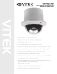
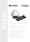
VT-PTZ10
Ultra-Compact PTZ Camera
with 10x Optical Zoom
VITEK
• Built-In 3.8-38mm Lens with 10x Optical / 10x Digital Zoom.
• High Performance 1/4” CCD with 500 TV Lines.
• True Day/Night function with ICR.
• 128 Presets programmed with view direction, zoom, and BLC.
• 4 Patterns record and play back user preference of surveillance path up to 120º sec.
• 8 Scans: 8 speed steps from slow to medium panning with smooth Diagonal Scan.
• 4 Tours: Each tour consists up to 32 Presets, Patterns, and/or Scans.
• 4 Alarm inputs with 1~4 priority / 1 Auxiliary output with programmable NC & NO.
• 8 Privacy Zones: Video off or up to 8 masked blocks
• 64 steps of variable speed from 0.4?/sec to 90?/sec. Max manual speed 190?/sec with
Turbo key pressed, Preset speed is 380?/sec.
• Built-in RS-485 receiver driver.
• Built-in power-line surge protection and lightning protection.
• Optional Wall Mount, Indoor/Outdoor pendant housing, and Heater & Blower Kit
CYAN
MAGENTA
YELLOW
BLACK
VT-PTZ10
UNPACKING
Before installing the Dome camera, please make sure that the following items are included in
the box:
1. Mini Speed Dome Camera
2. Instruction Manual
3. Mounting Hardware
If any of these materials are missing, please contact the vendor or VITEK customer help desk
immediately.
1
VT-PTZ10
DISCLAIMER
•
•
•
•
While every effort has been made to ensure that the information contained in this guide is
accurate and complete, no liability can be accepted for any errors or omissions.
VITEK reserves the right to change the specifications of the hardware and software
described herein at any time without prior notice.
No part of this guide may be reproduced, transmitted, transcribed, stored in a retrieval
system, or translated into any language in any form, by any means, without prior written
permission of VITEK.
VITEK makes no warranties for damages resulting from corrupted or lost data due to a
mistaken operation or malfunction of the Speed Dome Cameras, peripheral devices, or
unapproved/unsupported devices.
2
VT-PTZ10
WARNING AND CAUTION
WARNING
TO REDUCE THE RISK OF FIRE OR ELECTRIC SHOCK, DO NOT EXPOSE THIS PRODUCT TO RAIN
OR MOISTURE. DO NOT INSERT ANY METALLIC OBJECTS THROUGH THE VENTILATION GRILLS OR
OTHER OPENINGS ON THE EQUIPMENT.
CAUTION
EXPLANATION OF GRAPHICAL SYMBOLS
The lightning flash with arrowhead symbol, within an equilateral triangle, is intended to
alert the user to the presence of uninsulated "dangerous voltage" within the product's
enclosure that may be of sufficient magnitude to constitute a risk of electric shock to
persons.
The exclamation point within an equilateral triangle is intended to alert the user to the
presence of important operating and maintenance (servicing) instruction in the literature
accompanying the product.
3
VT-PTZ10
FCC COMPLIANCE STATEMENT
FCC INFORMATION: THIS EQUIPMENT HAS BEEN TESTED AND FOUND TO COMPLY
WITH THE LIMITS FOR A CLASS A DIGITAL DEVICE, PURSUANT TO PART 15 OF THE
FCC RULES. THESE LIMITS ARE DESIGNED TO PROVIDE REASONABLE PROTECTION
AGAINST HARMFUL INTERFERENCE WHEN THE EQUIPMENT IS OPERATED IN A
COMMERCIAL ENVIRONMENT. THIS EQUIPMENT GENERATES, USES, AND CAN
RADIATE RADIO FREQUENCY ENERGY AND IF NOT INSTALLED AND USED IN
ACCORDANCE WITH THE INSTRUCTION MANUAL, MAY CAUSE HARMFUL
INTERFERENCE TO RADIO COMMUNICATIONS. OPERATION OF THIS EQUIPMENT IN A
RESIDENTIAL AREA IS LIKELY TO CAUSE HARMFUL INTERFERENCE IN WHICH CASE
THE USER WILL BE REQUIRED TO CORRECT THE INTERFERENCE AT HIS OWN
EXPENSE.
CAUTION: CHANGES OR MODIFICATIONS NOT EXPRESSLY APPROVED BY THE PARTY
RESPONSIBLE FOR COMPLIANCE COULD VOID THE USER'S AUTHORITY TO OPERATE
THE EQUIPMENT.
THIS CLASS A DIGITAL EQUIPMENT COMPLIES WITH CANADIAN ICES-003.
CET APPAREIL NUMÉRIQUE DE LA CLASSE A EST CONFORME À LA NORME NMB-003
DU CANADA.
CE COMPLIANCE STATEMENT
WARNING
THIS IS A CLASS A PRODUCT. IN A DOMESTIC ENVIRONMENT THIS PRODUCT MAY
CAUSE RADIO INTERFERENCE IN WHICH CASE THE USER MAY BE REQUIRED TO
TAKE ADEQUATE MEASURES.
4
VT-PTZ10
IMPORTANT SAFEGUARDS
1.
2.
3.
4.
5.
6.
Read these instructions.
Heed all warnings.
Follow all instructions.
Do not use this equipment near water.
Clean only with dry cloth.
Do not block any ventilation openings. Install in accordance with the manufacturer's
instructions.
7. Do not install near any heat sources such as radiators, heat registers, stoves, or other
equipment (including amplifiers) that produce heat.
8. Do not defeat the safety purpose of the polarized or grounding-type plug. A polarized plug
has two blades with one wider than the other. A grounding type plug has two blades and
a third grounding prong. The wide blade or the third prong is provided for your safety. If
the provided plug does not fit into your outlet, consult an electrician for replacement of the
obsolete outlet.
9. Protect the power cord from being walked on or pinched, particularly at plugs,
convenience receptacles, and the point where they exit from the equipment.
10. Only use attachments/accessories specified by the manufacturer.
11. Unplug this equipment during lightning storms or when unused for long periods of time.
12. Refer all servicing to qualified service personnel. Servicing is required when the
equipment has been damaged in any way, such as power-supply cord or plug is damaged,
liquid has been spilled or objects have fallen into the equipment, the equipment has been
exposed to rain or moisture, does not operate normally, or has been dropped.
13. CAUTION - THESE SERVICING INSTRUCTIONS ARE FOR USE BY QUALIFIED
SERVICE PERSONNEL ONLY. TO REDUCE THE RISK OF ELECTRIC SHOCK DO
NOT PERFORM ANY SERVICING OTHER THAN THAT CONTAINED IN THE
OPERATING INSTRUCTIONS UNLESS YOU ARE QUALIFIED TO DO SO.
Use Certified/Listed Class 2 power supply transformer only.
5
VT-PTZ10
TABLE OF CONTENTS
DISCLAIMER ..................................................................................................................2
WARNING AND CAUTION .............................................................................................3
FCC COMPLIANCE STATEMENT .................................................................................4
CE COMPLIANCE STATEMENT....................................................................................4
IMPORTANT SAFEGUARDS .........................................................................................5
I. INTRODUCTION .........................................................................................................8
Features................................................................................................................................................... 8
II. INSTALLATION AND CONFIGURATION...................................................................9
2.1 Typical System Configuration......................................................................................................... 9
2.2 Basic Configuration of Speed Dome Camera System................................................................ 10
2.3 Connecting the Speed Dome directly into the DVR .................................................................... 11
2.4 Connecting the Speed Dome into the Controller via J-box ....................................................... 11
2.5 Connecting Both Speed Dome and DVR via J-box ..................................................................... 12
2.6 Principle of Termination ................................................................................................................ 14
2.7 Dome Camera Address (ID) ........................................................................................................... 16
2.8 Setting Protocols ............................................................................................................................ 16
2.9 Connections .................................................................................................................................... 17
3.0 Mounting the Dome Camera.......................................................................................................... 18
3.1 Power on and Boot-up Sequence ................................................................................................. 19
III. PROGRAM & OPERATION .....................................................................................20
Dome Camera Selection ...................................................................................................................... 20
3.1 FUNCTIONS..................................................................................................................................... 21
3.1.1 HOME FUNCTION (MENU =>FUNCTIONS => HOME FUNCTION) .................................................................................21
3.1.2 PRESET (MENU => FUNCTIONS => PRESET Short Cut:PRST ).....................................................................................22
3.1.3 PATTERN (MENU => FUNCTIONS => PATTERNS or Shortcut: PTRN) ...........................................................................24
3.1.4 SCAN ( MENU => FUNCTIONS => SCAN or Shortcut: SCAN) ........................................................................................25
3.1.5 TOUR (or MENU => FUNCTIONS => TOUR, Short Cut: TOUR)................................................................................27
3.2 ALARM ( MENU => ALARM) ......................................................................................................... 29
3.3 SCREEN........................................................................................................................................... 30
3.3.1 LANGUAGE ( MENU => SCREEN => LANGUAGE) .........................................................................................................30
3.3.2 PRIVACY ZONE ( MENU => SCREEN => PRIVACY ZONE) ...........................................................................................31
3.3.3 NORTH DIRECTION ( MENU => SCREEN => NORTH DIRECTION)..............................................................................32
3.3.4 ZONE TITLE ( MENU => SCREEN => ZONE TITLE) ....................................................................................................32
3.3.5 CAMERA TITLE ( MENU => SCREEN => CAMERA TITLE) .........................................................................................33
3.3.6 OSD DISPLAY ( MENU => SCREEN => OSD DISPLAY) ..............................................................................................33
3.4 CAMERA ( MENU => CAMERA) ..................................................................................................... 34
3.4.1 FOCUS CONTROL( MENU => CAMERA => FOCUS CONTROL) ...................................................................................34
3.4.2 WB (white balance) ( MENU => CAMERA => WB CONTROL) .........................................................................................34
3.4.3 AE CONTROL ( MENU => CAMERA => EXPOSURE SETUP) ........................................................................................35
3.4.4 BACK LIGHT COMPENSATION ( MENU Î CAMERA ÎBack Light)...............................................................................35
3.4.5 SHARPENSS CONTROL ( MENU => CAMERA =>SHAPENESS)...................................................................................35
3.4.6 DIGITAL ZOOM ( MENU => CAMERA =>DIGITAL ZOOM) ..............................................................................................36
6
VT-PTZ10
3.4.7 NIGHT SHOT MENU ( MENU => CAMERA =>NIGHT SHOT)..........................................................................................36
3.4.8 CAMERA INITIALIZE ( MENU => CAMERA =>CAMERA INITIALIZE) .............................................................................36
3.5 SETUP ( MENU => SETUP) ............................................................................................................. 37
3.5.1 FLIP (MENU => SETUP => FLIP).....................................................................................................................................37
3.5.2 SPEED (MENU => SETUP => SPEED)............................................................................................................................37
3.5.3 PRESET FREEZE (MENU => SETUP => PRESET FREEZE).........................................................................................37
3.5.4 PANNING RANGE (MENU => SETUP => PANNING RANGE).........................................................................................37
3.5.5 CALIBRATION (MENU => SETUP => CALIBRATION) .....................................................................................................38
3.5.6 LINE LOCK CONTROL (MENU => SETUP => LINE LOCK CONTROL) ..........................................................................38
3.5.7 FACTORY DEFAULT (MENU => SETUP => FACTORY DEFAULT)................................................................................38
3.5.8 ERASE DATA (MENU => SETUP => ERASE DATA) .......................................................................................................39
3.5.9 SYSTEM INFORMATION (MENU => SETUP => SYSTEM INFORMATION) ...................................................................39
Appendix A — Specifications.............................................................................................................. 40
Appendix B — Troubleshooting.......................................................................................................... 42
Glossary .......................................................................................................................43
7
VT-PTZ10
I. INTRODUCTION
Features
The Speed Dome Camera features a high resolution 1/4” Interline Transfer CCD imager for
enhanced lowlight sensitivity. User friendly, on-screen pull-down menus and short-cuts make
it easy to setup and program functions.
System information aides trouble shooting by displaying the hardware and software version of
the camera’s firmware version, baud rate, and protocol.
• Built-in 10X times Optical Power Zoom Camera.
True Night Shot function with ICR Day/Night function.
• 128 Presets programmed with view direction, zoom, and BLC.
• 4 Patterns record and play back user preference of surveillance path up to 120 sec.
• 8 Scans: 8 speed steps from slow to medium panning with smooth DiagonalScan.
• 4 Tours: Each tour consists up to 32 Preset, Pattern, and Scan.
Smooth DiagonalScan mode and programmable Individual dwell time camera functions.
(Speed, Dwell time BLC, Focus, IRIS of the preset)
• 4 Alarm inputs with 1~4 priority / 1 Auxiliary outputs programmable NC & NO.
• 8 Privacy Zones: Video off or up to 8 masked blocks
• 64 steps of variable speed from 0.4°/sec to 90°/sec.
Max manual speed 190°/sec with Turbo key pressed, Preset speed is 380°/sec.
• Programmable user preferences of speed (Slow, Medium, and Fast).
• Addressable up to 99 camera IDs (Extendable up to 3999 in special mode).
• Built-in RS-485 receiver driver.
• On-site software upgrade and upload/download of programmed data into the KBD/Dome.
• Built-in power-line surge protection and lightning protection.
• Optional Tinted Bubble, Indoor & Outdoor pendant housing, Heater & Blower.
Flush Mount Kit
8
VT-PTZ10
II. INSTALLATION AND CONFIGURATION
2.1 Typical System Configuration
Additional Speed Dome joystick controllers and a variety of external switching devices such
as multiplexers (MUXes) and Digital Video Recorders (DVRs) may be incorporated to
accommodate the needs from a small to a large surveillance/security system.
Figure 1 illustrates sample installation.
Figure 1 - Typical System Configuration
9
VT-PTZ10
2.2 Basic Configuration of Speed Dome Camera System
POWER
AC 24V
STP AWG # 22
/T
R
X)
BNC MONITOR
TRXTRX+
.(T
R
M
ER
W 4V
POC 2
A
ER
AT
HE 24V
C
A
TRXTRX+
C
O
M
RS-485
HALF DUPLEX MODE
EO
VID
X+
4 ALARM INPUT
1 AUX OUTPUT
CONTROLLER
DOME
Figure 2 - Basic Installation Diagram
10
VT-PTZ10
2.3 Connecting the Speed Dome directly into the DVR
•
•
Locate the RS485 + & - conductor wire from the Speed Dome Camera.
Connect the + & - into the TRX+ & TRX- ports of the DVR. Tx+ & Tx- ports can be found in
the rear part of the DVR.
Figure 3 - Camera into DVR
2.4 Connecting the Speed Dome into the Controller via J-box
Figure 4 - Camera into Controller
11
VT-PTZ10
2.5 Connecting Both Speed Dome and DVR via J-box
Figure 5 - Connecting Camera & DVR into Controller
12
VT-PTZ10
Power AC 24V~
Comm.(RX/TX)
Video
Heater AC 24V~
4 Alarm Input
1 Aux Output
The dome camera must be installed by qualified service personnel. Before installing the dome
camera system, this instruction manual must be read thoroughly and understood fully. Dome
cameras must be set up properly before starting the installation. This involves properly setting
configuration switches. Figure 6 shows the location of these switches.
Address(ID)
Selection Switches
Figure 6 - Layout of Switches
13
6789
0
5
4 3 21
Fan
6789
0
5
4 3 21
S5
Termination
Protocol
S2
S1
S4
S3
VT-PTZ10
2.6 Principle of Termination
Every device that is connected at the end of the communication data line must be terminated
by either the DIP switch setting or an appropriate device such as a termination jumper to
prevent potential control signal errors.
See Figure 6 for termination switch settings and Figure 7 for examples of devices requiring
termination. Note: Total length of the cable for communication should not exceed 1.2Km
or .74 mile.
S5
Terminated
Not terminated
Pull Up/Down **
Normal **
D1
Not
Used
D2
X
X
ON
OFF
** Unless communication error, put the position 2, 3 of the S5 in OFF state.
should be set as a pair. (Both 2, 3 to ON position or OFF position)
Figure 7 - Setting Dome Camera Termination
14
D3
X
X
ON
OFF
D4
ON
OFF
X
X
Position 2, 3
VT-PTZ10
S1:Dome1 port Termination ON
DVR Termination ON
SW1:Termination ON
SW1:Termination ON
S1:Dome1 port Termination ON
DVR Termination ON
SW1:Termination ON
SW1:Termination ON
SW1:Termination ON
SW1:Termination ON
S1:Dome1 port Termination ON
S4:DVR port Termination ON
DVR Termination ON
DVR Termination ON
SW1:Termination ON
S3:Dome2 port Termination ON
SW1:Termination ON
Figure 8 - Termination Diagram
15
TERMINATION ON
S1:Dome1 port Termination ON
SW!:Termination ON
SW1:Termination ON
SW1:Termination ON
VT-PTZ10
2.7 Dome Camera Address (ID)
Each dome camera must have a unique address (ID). Identical IDs on the same line may
damage the control circuit caused by an electrical short. When installing multiple dome
cameras or a DVR, it is recommended that the dome camera ID’s be identical to the camera
port of the DVR.
Cam Port 1 = Dome ID1, Cam Port 2 = Dome ID 2 … Cam Port 16 = Dome ID 16.
If more than 16 dome cameras are installed using two or more DVRs the following formula is
useful to determine the Dome ID: ID =16x (n-1) +m (where n= number of DVR, m=Camera
Port)
Refer to Figures 9 for setting the dome camera address (ID) and protocol selection.
DOME ID
1
.
99
6
5
4
6
7
3
7
8
2
8
9
0
1
9
0
1
S4
2
D1 . . D4 D5 . . D8
3
on
5
4
on
S2
0
.
9
S1
1
.
9
S3
S1
S2
Figure 9 - Setting Dome Camera Address (ID) and Protocol
2.8 Setting Protocols
A Speed Dome camera is capable of negotiating with multiple protocols if the communication
speed is matched (same baud rate i.e., 9600 bps). See Figure 10 for the appropriate protocol
switch settings.
Note: Consult service personnel if a dome camera is installed with a device other than a
recommended Speed Dome Controller.
Dip S/W
D1
D2
S4
D3
D4
D5
D6
S3
D7
D8
Baud Rate
2400 bps
4800 bps
9600 bps
19200 bps
38400 bps
Function
Protocol
AUTO Selection(no parity)
DEFAULT
AUTO selection(even parity)
PP
EZ
S2
PD
VC
SN
DC
KReserved
PPS
SReserved
SReserved
VVL
DDI
Reset
Protocol
Baud Rate
Extended ID
D5
Off
Off
Off
Off
ON
Extended ID
1~99
1~3999
D6
Off
Off
ON
ON
Off
D7
Off
ON
Off
ON
Off
D8
Off
On
Figure 10 - Protocol Selection tables
16
D1
D2
D3
D4
Off
Off
Off
Off
On
Off
On
Off
On
Off
On
Off
On
Off
On
Off
On
Off
On
Off
On
On
Off
Off
On
On
Off
Off
On
On
Off
Off
On
On
Off
Off
Off
On
On
On
On
Off
Off
Off
Off
On
On
On
On
Off
Off
Off
Off
Off
Off
Off
On
On
On
On
On
On
On
On
VT-PTZ10
2.9 Connections
• How to Connect RS485
The dome camera has a built-in RS-485 receiver so that it can be controlled
remotely by an external control device such as a joystick controller or a DVR.
RS-485: Connect the TXA (Tx+) and TXB (Tx-) of the RS485 control devices (KBD,
DVR…) to TRX+, TRX- of the dome camera.
RS-485 does not allow for a star connection layout. A splitter is required if a star
connection layout is desired. RS-485 guarantees 1.2 Km of data line routing. A
repeater is recommended to extend over 1.2 Km.
• Connecting Video output
Figure 2 – Basic installation diagram
• Connecting Alarms
AL1 to 4 (Alarm In)
Magnetic, PIR or other external sensor devices can be used to signal the dome
camera reacting to an event.
See Chapter 3.2 — Program and Operation for configuring alarm input.
GND (Ground)
NOTE: All the connectors marked GND are common.
Connect the ground of the Alarm input and/or alarm output to the GND connector.
NO / NC (Normally Opened or Normally Closed dry contact relay output)
The dome camera can activate external devices such as buzzers or lights using dry
contact relays. Connect the device to the NO (NC) (Alarm Out) and COM
(Common) connectors. See Chapter 3 — Program and Operation for configuring
alarm output.
• Connecting the Power
Connect AC 24V 40VA power to the dome camera.
Use certified / Listed Class 2 power supply transformer only.
17
VT-PTZ10
3.0 Mounting the Dome Camera
Once all DIP switches are set properly and all external connections are made, the dome
camera can be mounted.
The Mini PTZ Dome camera is designed to mount on a structural body supporting loads up
to 3 Kg. See Figure 11.
Installation Hint
Using Four ST4X30 screws, affix flush mount base to sturdy surface
Figure 11 - Example of a flush mounted installation
18
VT-PTZ10
3.1 Power on and Boot-up Sequence
When the power is applied to the dome camera, it will start the boot-up sequence. When
boot-up is done, the following information is displayed on the monitor screen.
RAM
CHECK
CHECK
CHECK
TEST
NO. : OK!
AAAA : OK!
5555 : OK!
SD SERIES
Vx.xxx
CAMERA TYPE xxxx
WAIT DOME SETTING.
INIT TILT ORIGIN SET OK
INIT PAN ORIGIN SET OK
INIT CAMERA SET OK
On Screen Display in normal control mode
Preset No.
001PRESET
W→
Compass Direction
Preset Title
Or Area Title
Information
EMPTY DATA !
Dome Camera Title
Alarm Display
ALARM:1
360.0,090.0
CAM xxxx
Pan & Tilt Angle
19
Dome Camera ID
VT-PTZ10
III. PROGRAM & OPERATION
Dome Camera Selection
Prior to start programming or operating a dome camera, please make sure that both the
camera and the joystick controller are communicating. In order for changes to take effect for
a camera, particular camera’s ID must be selected on the controller.
Example: Pressing 1 , 6 and CAM key sequentially will select dome camera 16. The selected
dome camera ID will be displayed on the monitor.
Principle of joystick usage in the programming (editing) mode
Button or Joystick movement in menu
Joystick left or right
Joystick up or down
Joystick down
Zoom handle twist
SHFT + Joystick
ESC
Home or Off button
Function
Go into the sub-menu items.
Execute the command(exit)
Change value.
Navigate through the menu items.
Navigate through the menu items.
Finish editing title.
Change value.(Increase / Decrease)
Enter editing title mode.
PTZ control mode.
Escape from the menu without change.
Delete value or name of the field.
20
VT-PTZ10
3.1 FUNCTIONS
By pressing the MENU button on the keyboard controller, the following On-screen MAIN
MENU will be shown on the monitor screen.
MAIN MENU
FUNCTIONS
ALARM
SCREEN
CAMERA
SETUP
EXIT
and then move the joystick
Select the FUNCTIONS
to the right to access FUNCTIONS menu.
FUNCTIONS
HOME FUNCTION
PRESET
PATTERN
SCAN
TOUR
EXIT
3.1.1 HOME FUNCTION ( MENU =>FUNCTIONS => HOME FUNCTION)
After HOME FUNCTION item has been selected, follow the directions below to set HOME
function.
HOME FUNCTION
FUNCTION
:
NUMBER
:
TIME
:
OPERATION
:
SAVE AND EXIT
FUNCTION
NUMBER
TIME
OPERATION
: Tour/ Preset/ Pattern/ Autoscan
: --: 10~240 Seconds
: DISABLE
21
TOUR
--60 SEC
DISABLE
VT-PTZ10
The HOME function applies to the predefined functions such as Preset, Tour, Pattern, or
Scan function after the keyboard controller has been idle for a programmed time.
Follow the steps below to program the Home function:
1.
2.
3.
4.
5.
Select the camera number by pressing No. and CAM
Press MENU to display the main menu on the monitor.
Moving the Joystick to the right on “FUNCTIONS”.
Enter Home Function menu by moving the Joystick to the right.
Moving the Joystick to the right/ left (or twist CCW/CW) to scroll Tour, Pattern, and
Auto Scan and Preset functions.
6. Select Function Number by pulling the Joystick down, and twist the Joystick to the
CCW/CW (or turn right/left). The executable function number will be scrolled. If selected
function is not programmed, it won’t change. Go to setup function first.
7. Pull the Joystick down and twist the Joystick to CCW/CW (or twist the joystick to
right/left) to set waiting time.
8. Highlight OPERATION option by pulling the Joystick down. Choose operation status
Enable or Disable by moving the Joystick to the right or to the left (or twist CCW/CW).
3.1.2 PRESET ( MENU => FUNCTIONS => PRESET Short Cut: PRST )
Preset stores pan, tilt, zoom, focus and iris settings. Once programmed, pressing combination
of 0 ~9 numbers and the Preset button on the controller should automatically call up the
preset position. Presets may be assigned to alarm actions or as the “home” position for the
dome camera.
Highlight PRESET and then move the joystick to the right to enter PRESET menu.
FUNCTIONS
HOME FUNCTION
PRESET
PATTERN
SCAN
TOUR
EXIT
There are 8 pages of preset programming menu. Each page can hold up to 8 presets. Locate
the “PREV
NEXT”, preset menu pages can be scrolled by moving the Joystick to the
Left or Right on the “PREV
NEXT”.
22
VT-PTZ10
PRESET
01/8
NO. F I B TITLE
001 A A F xxxxxxxxxxxxxxxx
002 M M O ---------------003 - - - ---------------004 - - - ---------------005 - - - ---------------006 - - - ---------------007 - - - ---------------008 - - - ---------------PREV
NEXT
SAVE AND EXIT
F
X
█
:
:
:
:
Focus I : IRIS B : BLC
16 digit of preset title
not defined
Current cursor position
Follow the steps below to program the Preset positions.
1. Select the camera number by pressing 0 ~ 9 and CAM .
2. Simply press PRST button to enter preset menu. ( MENU => FUNCTIONS =>
PRESET)
3. Select the empty preset location to be programmed by moving the Joystick up/down. If
selected location is not empty, pressing PRST button will display the predefined position.
4. After selecting an empty position, press and hold SHFT/PGM then use the Joystick to
control the direction of the camera and lens.(Or twist the zoom handle or press the zoom
button to start PTZ control for view selection.)
5. After aiming the camera (view direction and lens control) to a specific position, release
SHFT/PGM button (or hit the focus button). The selected location No. field will be filled
with “A A F”. Move the joystick to the right to select each Focus/ Iris /BLC mode using
zoom handle.
6. Move to the title field to edit/enter the name. Rotate the handle CW and CCW or press
Tele or Wide button to scroll through the alphanumeric characters. Moving the handle to
right or left to select next or previous digit.
7. To finish entering the title, move the Joystick up/down.
8. Locate the cursor on “PREV NEXT” item to select the previous/next page of presets,
scroll through the page by moving the Joystick to the Left on “PREV NEXT”.
9. Repeat the steps 2 through 8 for each additional preset position.
10. Select Save and Exit by moving the Joystick to the right. Press ESC to exit the Preset
menu without saving.
NOTE: Press the Home or OFF button at programmed position to delete the preset.
23
VT-PTZ10
SHORTCUT TO PROGRAMMING PRESETS.
Select direction of the camera, zoom and focus to be programmed, then press No. (1~64),
and then press SHFT, PRST subsequently. The current view will be stored to the selected
preset number if position is empty. If selected preset number is not empty, “PRESET
EXISTING” message will be displayed on the monitor and you will be prompted to overwrite.
Example: 1 , 0 + PGM + PRST will memorize current view as preset No. 10. In this case, focus
and Iris mode will be memorized as auto and dwell time will be set to 3 sec.
3.1.3 PATTERN ( MENU => FUNCTIONS => PATTERNS or Shortcut: PTRN )
The Pattern function memorizes and stores movement of the selected dome camera for up to
60 seconds. Pattern can be stored in 60 seconds of total recording space. Stored pattern is
played back by pressing No.+ PTRN buttons subsequently.
PATTERN SETUP
NO.
TITLE
SEC
01 : xxxxxxxxxxxxxxxx 000
02 : xxxxxxxxxxxxxxxx
03 : xxxxxxxxxxxxxxxx
04 : xxxxxxxxxxxxxxxx
TOTAL :
000
SAVE AND EXIT
Follow the steps below to program the Pattern:
1. Press MENU key to display the main menu on the monitor.
2. Simply press the PTRN key. (or MENU => FUNCTIONS =>PATTERN)
3. Select the empty Pattern number to be programmed by moving the Joystick Up or
Down. If SEC column is not 000, then the selected No. of pattern is already recorded.
4. Press and hold down the SHFT/PGM key while controlling the camera direction and
zoom with the Joystick. The pattern movement will automatically be recorded until
releasing the SHFT/PGM key. This procedure can be repeated to reprogram the pattern.
(Or twist zoom handle or hit zoom button to start PTZ control for view selection and hit
the Focus button to stop.)
5. Scroll down to the Save and Exit option and move the Joystick to the right to save
and exit.
6. Naming the Pattern can be done by twisting the Joystick. Rotate the handle
clockwise or counterclockwise to scroll through the alphanumeric characters, move the
handle to right or left to select next or previous space.
24
VT-PTZ10
7. Pressing ESC will not save recorded data and will exit to the previous menu. Press the
HOME or OFF button at any programmed position to delete the programmed pattern.
NOTE: If total recording time reaches 120 seconds, it will automatically stop for a
moment and start recording again. Previous data will be overwritten.
3.1.4 SCAN ( MENU => FUNCTIONS => SCAN or Shortcut: SCAN )
The Scan function supports up to 4 programmed sections of angles at 8 programmable
speeds.
SCAN MENU
01/8
SCAN 01
: AUTOSCAN01
SPEED
: 1~8/SLW/MID
START
: NONE
END
: NONE
DIRECTION : CCW
SWAP
: OFF
SAVE AND EXIT
SPEED (MODE):
1/ 2 / 3/ 4/ 5/ 6/ 7/ 8/ SLOW / MEDIUM
1: SLOWER ↔ 8 FASTER
SLW : smooth DiagonalScan in slowest speed
MID : smooth DiagonalScan in medium speed
DiagonalScan shows moving path from start point to end point including
tilt and zoom** simultaneously.
**Some models do not change zoom ratio
25
VT-PTZ10
Follow the steps below to program Scans.
1. Press the SCAN key to enter Auto Scan menu directly. (Or MENU => FUNCTIONS =>
SCAN).
2. Select an Auto Scan number by moving the Joystick left or right.
3. Twist the Joystick to enter the title by scrolling through the alphanumeric characters
and move the handle to the right or left to move to the next space. Press ENTR key or
move the Joystick down to finish title mode.
4. When finish entering the title, select “START ANGLE” with the Joystick. Hold down
the SHFT/PGM key while selecting the start position using the Joystick. Current
panning position will be displayed. Release SHFT/PGM key to complete the selection of
the start position. (Or twist zoom handle or hit zoom button to start PTZ control for view
selection and hit the Focus button to stop.)
5. Move the Joystick downward to select “END ANGLE.” Hold down the SHFT/PGM key
while moving the Joystick to select the end position. The end position angle should be
larger than start position. Release the SHFT/PGM key to complete the selection of the
end position. (Or twist zoom handle or hit zoom button to start PTZ control and hit the
Focus button to stop.)
6. Move the Joystick downward to select “Tilt & Zoom.” Set the zoom and tilt angle by
holding down the SHFT/PGM key.
7. Moving the Joystick downward to select “Speed” and set the speed by twisting the
Joystick clockwise or counterclockwise or move the Joystick left/ right to select
the auto scan speed.
8. Select Save and Exit by moving the Joystick to the right. Press ESC to exit the
program without saving.
Pressing the HOME or OFF button to delete stored data, 000 will be displayed immediately.
26
VT-PTZ10
3.1.5 TOUR (or MENU => FUNCTIONS => TOUR, Short Cut: TOUR)
There are 4 programmable Tours. Each Tour consists of up to 8 Preset positions, Patterns,
Scans or other Tours. Using second-level Tours, it can be expanded up to 56 functions in a
single Tour. However tours in the second level Tour will be ignored when called by the first
level Tour. This can be best illustrated by the following example:
If Tour
Tour
Tour
Tour
01
02
03
04
:
:
:
:
Preset 02, Preset 03,Tour 02, Tour 03
Preset 05, Preset 06, Tour 04, Preset 05
Preset 07, Pattern 01
Preset 08. Preset 05, Pattern 01
Tour1 executes as follows:
Preset 02 Î Preset 03 Î Preset 05 Î Preset 06 Î Preset 05 Î Preset 07 Î
Pattern 01 Î ... (Repeat) ---Tour 04 in Tour 02 will be skipped in Tour 01
Tour 02 executes as follows:
Preset 05 Î Preset 06 Î Preset 08 Î Preset 05 Î Pattern 01 ÎPreset 05 …
Repeat (Tour 04 is still valid if called directly from Tour 02.)
TOUR 01:xxxxxxxxxxxxxxxx
01/04
FUNC
PRST
PTRN
SCAN
TOUR
------------PREV
SAVE
xxxxx
--Speed
DWell
PRST
PTRN
SCAN
TOUR
NO
064
004
016
004
---------
S DW TITLE
S 03 ---------------S 03 ---------------S 03 ---------------S 03 ---------------- 03 ---------------- 03 ---------------- 03 ---------------- 03 ---------------NEXT
AND EXIT
: 16 digits of title for tour label
: blank preset position
: F-Normal/ M- Medium D.Scan/ S- Slowest D.Scan
: 03-99 Sec
: PRESET 1~64
: PATTERN 1
: SCAN 1~4
: TOUR 2~4
27
VT-PTZ10
Follow the steps below to program the Tours:
1. Press MENU => FUNCTIONS => TOUR, Short Cut: TOUR MENU to display the main
menu on the monitor. No. + SHFT + TOUR will open directly Tour No.
2. Choose an empty location of function by moving the Joystick up or down.
3. Stored Preset view can be recalled by pressing Prst button, the camera will move to
the stored Preset view.
4. To place predefined functions as a Tour, press the function buttons (such as Tour,
Ptrn, or Scan ,Prst ).
Then select function No. by twisting the Zoom handle. (Programmed function No. will be
scrolled).
To remove functions from the Tour, press the HOME or Off button, blank position mark (- -) will be displayed. You can overwrite the programmed position.
5. Repeat Step 2 through 4 for each desired position. Each title will be displayed on top of
the line.
6. Up to 8 Presets, Tours, Patterns Scans can be selected for a Tour. You can expand the
Tour sequence by calling other programmed tours. Moving the Joystick handle to
right or left while the cursor is on the top of the line (TOUR 01) to select another page of
the Tour menu. (TOUR 01)
8. You can enter a title for the selected Tour by twisting the Joystick while the cursor is
on the top of the line (TOUR 01). Rotate the handle clockwise or counterclockwise to
scroll through the alphanumeric characters. Move the handle to the right or left to select
the next or previous digit.
9. Select Save and Exit by moving the Joystick to the right. Press ESC to exit the
program without saving.
NOTE: All functions should be programmed before being referred to in the tour menu.
Otherwise functions won’t be selectable by item 4 in the procedure.
28
VT-PTZ10
3.2 ALARM ( MENU => ALARM)
MAIN MENU
FUNCTIONS
ALARM
SCREEN
CAMERA
SETUP
EXIT
Highlight ALARM in the main menu and move the joystick to the right to access ALARM
setup.
ALARM SETUP
NO
01
02
03
04
FUNC PRI
P01
0
048
3
001
1
--3
IN
OFF
OFF
OFF
OFF
OUT
OFF
OFF
OFF
OFF
HLD LATCH
001 OFF
001 OFF
001 OFF
001 OFF
SAVE AND EXIT
NO
FUNC
: Alarm input number
: Priority 1~4 calls Preset(xxx),
Priority 0 supports dedicated functions like a Pattern(Pxx), Tour(Txx),
Scan(Sxx).
PRI
: Lower No. has higher priority, Equal priority alarms will be serviced repeatedly.
IN
: NO/NC - normally open /Closed, OFF - ignore
OUT
: R01 - Relay out 1,
OFF - No output.
HLD
: Alarm will be held for programmed time (01 to 99 seconds)
LATCH : ON - Shows all alarms including past alarm, OFF - Shows activated alarms
only.
There are 5 levels of priority. 0 : Highest priority supports repeated/dedicated functions
like a Pattern(Pxx), Tour(Txx), Scan(Sxx). 1~4: Same level of alarm calls presets one
after the other.
Ex) Alarm 01 calls Pattern 01, after alarm 01 is released alarm 02, 03 will call preset 48
and preset 01
1. Press Menu to display the main menu on the monitor. Select the Alarm option by moving
the Joystick up/down and then move to the right to enter the detail menu.
29
VT-PTZ10
2. Select the alarm input number by moving the Joystick up or down and select the
column to setup. Selected position will be highlighted.
3. Select the Preset, Status of Input (NC/NO/OFF), and Output (OUT1~2/OFF) by moving
the Joystick to the right or to the left.
4. To increase or decrease the preset number or to change the status or output number,
twist the Joystick clockwise or counterclockwise. In case of preset, programmed
preset number will be scrolled.
5. Locate the cursor on Save and exit and moving the Joystick to the Save and exit.
Press ESC to exit the program without saving.
3.3 SCREEN
By pressing the MENU button on the keyboard controller, the following On-screen MAIN
MENU will be shown on the monitor screen.
MAIN MENU
FUNCTIONS
ALARM
SCREEN
CAMERA
SETUP
EXIT
Highlight SCREEN and then move the joystick to the right to enter SCREEN menu.
SCREEN MENU
LANGUAGE
PRIVACY ZONE
NORTH DIRECTION : 000.0
ZONE TITLE
CAMERA TITLE : DOME
OSD DISPLAY
EXIT
3.3.1 LANGUAGE ( MENU => SCREEN => LANGUAGE)
Moving the joystick handle to the right to select LANGUAGE options.
Preferred language will be scrolled by moving the joystick to the right on LANGUAGE
ENGLISH.
30
VT-PTZ10
3.3.2 PRIVACY ZONE ( MENU => SCREEN => PRIVACY ZONE)
Highlight PRIVACY ZONE and then move the joystick to the right to enter the menu.
SCREEN MENU
LANGUAGE
PRIVACY ZONE
NORTH DIRECTION : 000.0
ZONE TITLE
CAMERA TITLE : DOME
OSD DISPLAY
EXIT
This function disables the viewing of restricted areas for privacy reasons. It offers masking up
to 8 unwanted views in a camera.
PRIVACY ZONE SETUP
NO
TITLE
01 xxxxxxxxxxxxxxxx
02 xxxxxxxxxxxxxxxx
03
04
05
06
06
08
SAVE AND EXIT
MASK
ON BLOCK
OFF V.OFF
NONE ---NONE ---NONE ---NONE ---NONE ---NONE ----
1. Select the Privacy Zone option by moving Joystick Up or Down and move the joystick to
right to enter the detail menu.
2. Select the privacy zone number by moving the Joystick up or down.
3. To enter the zone name, rotate the handle clockwise or counterclockwise. Select
alphanumeric characters by rotating the handle. Move to the next character position by
moving the Joystick to the right. To finish entering the title, move the Joystick down or press
the ENTR key.
4. To adjust the “marked” (privacy) area, press and hold down the SHFT/PGM key and then
use the Joystick (direction and zoom) until getting desired view. Release the key, the right
column will be set to ON. (Or twist the zoom handle or hit the zoom button to start PTZ control
for view selection and hit the Focus button to exit from control mode.)
5. Use the Home key to delete the marked zone, or move the Joystick to the right or left to
turn the stored zone On or Off.
31
VT-PTZ10
6. Select the Save and Exit option by moving the Joystick up or down. Save and exit the
program by moving the Joystick to the right. Press ESC to exit the program without saving.
Press the HOME or Off button to delete programmed privacy zone.
3.3.3 NORTH DIRECTION ( MENU => SCREEN => NORTH DIRECTION)
Move the joystick handle to the right to select NORTH DIRECTION options.
1. Select DISPLAY option to turn on or off the function.
2. Move to POSITION item to set north direction, press and down the SHFT/PGM key and
then use the Joystick (direction and zoom) until to get the desired direction. Release the key
then current pan angle will be displayed on position item. (Or twist the zoom handle or hit the
zoom button to start PTZ control for view selection and hit the Focus button to exit from
control mode.)
3.3.4 ZONE TITLE ( MENU => SCREEN => ZONE TITLE)
Enter a specific name in sectioned angle between START and END.
ZONE TITLE
01/04
NO
TITLE
01 WINDOW
02
03
04
05
06
PREV
NEXT
SAVE AND EXIT
START END
123.4 345.6
----- -------- -------- -------- -------- ----
1. Press MENU => SCREEN => ZONE TITLE to display zone title menu on the monitor.
2. Select the zone number by moving the Joystick up or down. Select Start, End or number
column to be set by moving the handle to the right or left. The selected column will be
highlighted.
3. Twist the joystick handle on the No. column to enter zone title. Select alphanumeric
characters by rotating the handle. Move to the next character by moving the Joystick to
the right. To finish entering the title, move the Joystick down.
32
VT-PTZ10
4. To adjust panning limit, press the SHFT/PGM key and hold down. Then use the Joystick
to go the desired direction. The end limit must be in an increasing direction. (Start < End). (Or
twist the zoom handle or hit the zoom button to start PTZ control for view selection and hit the
Focus button to exit from control mode.)
5. PREV NEXT : go to previous page or next page of the menu
6. Save and exit the program by moving the Joystick to the right. Press ESC to exit the
program without saving.
3.3.5 CAMERA TITLE ( MENU => SCREEN => CAMERA TITLE)
Move the joystick handle to the right to select CAMERA TITLE options.
This function allows the users to set the title of camera as well as the usage of on screen
display of the title.
Twist the joystick handle on the CAMERA TITLE : DOME to enter camera title.
Select alphanumeric characters by rotating the handle. Move to the next character
by moving the Joystick to the right.
To finish entering the title, move the Joystick down.
3.3.6 OSD DISPLAY ( MENU => SCREEN => OSD DISPLAY )
OSD DISPLAY
FUNCTION DISPLAY
CAMERA TITLE
ZONE TITLE
NORTH DIRECTION
DOME POSITION
DOME ID.
ZOOM MAGNIFICATION
EXIT MENU
:
:
:
:
:
:
:
ON
ON
ON
ON
ON
ON
ON
FUNCTION TITLE : turn on or off the preset, pattern, scan, tour title display.
CAMERA TITLE : turn on or off the camera title display.
ZONE TITLE : turn on or off the zone title display.
NORTH DIRECTION : turn on or off the azimuth direction display.
DOME POSITION : turn on or off the coordinates display.
DOME ID : turn on or off the dome ID display.
ZOOM MAGNIFICATION : turn on or off the current zoom magnification level display.
33
VT-PTZ10
3.4 CAMERA ( MENU => CAMERA)
NOTE: The menu features will vary depending on the camera module.
CAMERA MENU
FOCUS CONTROL
WB CONTROL
EXPOSURE SETUP
BACK LIGHT
: OFF
SHARPNESS
: 31
DIGITAL ZOOM : OFF
(2X/4X/MAX)
NIGHT SHOT
CAMERA INITIALIZE
SAVE AND EXIT
3.4.1 FOCUS CONTROL( MENU => CAMERA => FOCUS CONTROL)
CAMERA MENU
FOCUS CONTROL: AUTO
MODE : AUTO / ONE-PUSH / MANUAL
AUTO : Focus is automatically adjusted with moving zoom.
ONE-PUSH : Focus is automatically adjusted just once, after zoom position is changed.
MANUAL : Focus can be manually adjusted, independent of moving zoom.
CAUTION: Please avoid continuous, 24-hour use of the auto focus under heavy
movement condition. This will shorten the lifespan of the lens.
3.4.2 WB (white balance) ( MENU => CAMERA => WB CONTROL)
WB SETUP
MODE
:
R GAIN :
B GAIN :
EXIT
OUTDOOR
30
40
34
VT-PTZ10
MODE
MANUAL / OUTDOOR / INDOOR / AWC
R GAIN
0 ~ 100
B GAIN
0 ~ 100
Use the AWC mode for normal use.
RGAIN / BGAIN modes are controllable only in MANUAL Mode
Moving the Joystick to the right or left to change.
NOTE: “ONE PUSH” means that when rotating the Joystick handle for a moment the
lens moves to adjust the focus for the subject. The focus lens then holds that position
until the Joystick handle rotation.
3.4.3 AE CONTROL ( MENU => CAMERA => EXPOSURE SETUP)
EXPOSURE SETUP
BRIGHT
IRIS
IRIS VALUE
SHUTTER
SHUTTER SPEED
AGC
DNR(SSNR)
DSS
EXIT MENU
:
:
:
:
:
:
:
:
025
AUTO
080
ESC(NOR)
1/60
NORMAL
OFF
AUTO
BRIGHT
:
0~100
IRIS
:
AUTO / MANUAL
IRIS VALUE
: 0 ~ 100
SHUTTER
: ESC(NOR) / MANUAL / A.FLK
SHUTTER SPEED : 2 ~ 1/120,000 sec
AGC
: NORMAL / HIGH / OFF
DNR(SSNR)
: OFF / LOW / MID. / HIGH
On screen noise reduction
DSS
: AUTO / OFF
This feature ensures clear images at night or under low lighting
conditions.
3.4.4 BACK LIGHT COMPENSATION ( MENU Î CAMERA ÎBack Light)
Objects in front of bright backgrounds will be clearer with BLC ON.
LOW / MID. / HIGH / OFF
3.4.5 SHARPENSS CONTROL ( MENU => CAMERA =>SHAPENESS)
Higher the value, outlines of the image will be enhanced (0~31)
35
VT-PTZ10
3.4.6 DIGITAL ZOOM ( MENU => CAMERA =>DIGITAL ZOOM)
OFF - Optical zoom only
2x,4x, Max. - Digitally magnifies up to 2x, 4x 10x respectively.
3.4.7 NIGHT SHOT MENU ( MENU => CAMERA =>NIGHT SHOT)
The NIGHT SHOT option removes the IR Cut filter of the camera and makes the
camera sensitive to near infrared.
If NIGHT SHOT mode of the selected camera is set to Manual, 10 + ON will enable
the NIGHT SHOT mode, 10 + OFF will turn off the NIGHT SHOT mode.
NIGHT SHOT SETUP
MODE
LOCAL CONTROL
EXIT
: AUTO
: COLOR
MODE : MANUAL / AUTO
AUTO – Camera automatically goes into B&W mode at low light.
MANUAL - Manually controls the Night Shot mode in LOCAL
CONTROL option. On/Off Night Shot mode remotely by pressing
10 + ON/ 10 + OFF.
3.4.8 CAMERA INITIALIZE ( MENU => CAMERA =>CAMERA INITIALIZE)
Returns all changed camera values to factory default.
CAMERA INITIALIZE
ARE YOU SURE : (Y/N)
YES : ENTER OR MENUKEY
NO : ESC KEY
36
VT-PTZ10
3.5 SETUP ( MENU => SETUP)
CONFIGURATION MENU
FLIP FUNTION : ON
P/T SPEED
: FAST
PRESET FREEZE : OFF
PANNING RANGE
CALIBRATION
LINE LOCK CONTROL
FACTORY DEFAULT
ERASE DATA
SYSTEM INFORMATION
SAVE AND EXIT
3.5.1 FLIP ( MENU => SETUP => FLIP)
When the Speed Dome camera is mounted on a ceiling, it can track a moving target in a path
directly below the camera:
ON - When the camera reaches the moving object directly above the floor, the dome camera
tracks the object smoothly with a digitally corrected image.
OFF – The dome camera does not perform a flip.
3.5.2 SPEED ( MENU => SETUP => SPEED)
User can select preferable speed curves of manual control.( FAST / MEDIUM / SLOW)
3.5.3 PRESET FREEZE ( MENU => SETUP => PRESET FREEZE)
This option is used to set the pause previous image until the preset action is complete.
3.5.4 PANNING RANGE ( MENU => SETUP => PANNING RANGE)
PAN RANGE SETUP
RIGHT LIMITE
: 000.0
LEFT LIMT
: 007.2
ENABLE : ON / OFF
SWAP RIGHT LEFT
SAVE AND EXIT
When the dome camera is installed near a wall or on a corner, panning range can be
limited by user.
37
VT-PTZ10
3.5.5 CALIBRATION ( MENU => SETUP => CALIBRATION)
CALIBRATION
RESET ORIGIN
ORIGIN OFFSET : 000.0 , 000.0
ACTIVE OFFSET : DISABLE/ENABLE
AUTO CALIBRATION : OFF
SAVE AND EXIT
RESET ORIGIN
: Calibrate the ORIGIN point.
OFFSET ORIGIN : Adjust the small amount of position error from re-installation.
ACTIVE OFFSET
: Apply the adjustment above or not
AUTO CALIBRATION : ON – When position error detected, recover automatically.
OFF – Disregard the position error.
3.5.6 LINE LOCK CONTROL ( MENU => SETUP => LINE LOCK CONTROL)
LINE LOCK SETUP
MODE
PHASE
EXIT
:
:
INTERNAL
(0~359)
MODE
INTERNAL / EXTERNAL
PHASE
0~359
EXIT (ESC TO EXIT)
Adjusts phase of picture with other
cameras in EXTERNAL mode.
3.5.7 FACTORY DEFAULT ( MENU => SETUP => FACTORY DEFAULT)
FACTORY DEFAULT
ARE YOU SURE : (Y/N)
YES : ENTER OR MENU KEY
NO : ESC KEY
Programmed data go back to initial state as ex-factory
38
VT-PTZ10
3.5.8 ERASE DATA ( MENU => SETUP => ERASE DATA)
ERASE PROGRAMMED DATA
ARE YOU SURE : (Y/N)
YES : ENTER OR MENU KEY
NO : ESC KEY
Erase programmed data in the EEPROM of the selected dome camera. Press MENU or
ENTER button to erase data, ESC key to exit without erasing. Origin offset value is not
affected.
CAUTION: Unless you download the data into a safe place, all the data in the selected dome
camera will be lost. (Refer to Download/ Upload data function in the Keyboard
Configuration utility)
3.5.9 SYSTEM INFORMATION ( MENU => SETUP => SYSTEM INFORMATION)
SYSTEM INFORMATION
CAMERA TYPE
H/W VERSION
ROM VERSION
PROTOCOL
BUADRATE
EXIT MENU
:
:
:
:
:
XXXXXXX
V1.00
V1.00
EZ
9600BPS
This screen shows information of the dome camera for service or trouble shooting
39
VT-PTZ10
APPENDIX A — SPECIFICATIONS
Lens
Camera(MS-Z10N/MS-Z10P)
Image Sensor
1/4" Interline Transfer CCD(Sony)
Picture elements
NTSC : 768x494 Approx. 380K pixels
PAL : 752x582 Approx. 440K pixels
Horizontal Resolution
500 TV Lines
Lens
10x optical zoom with auto focus
10x digital zoom
F1.8 to F3.0, f=3.8mm to 38mm
View angle
Approx. 51.2° (WIDE end) to 5.58° (TELE end)
Minimum Illumination
0.7 lux(F1.8,normal shutter speed)
0.02 lux (F1.8, IR Cut Filter Removed)
0.005 lux (F1.8, DSS Auto with IR Cut Filter Removed)
S/N ratio
more than 50dB
Controller specifications
General
Certification
Electrical
Input Voltage
CE EMC, FCC CLASS A
18 to 30 VAC; 24 VAC nominal, built-in power-line surge
Power Requirement
24 VAC/VDC 700mA
Power Consumption
Maximum 15W / 30W(Heater Use)
Alarm Output
Alarm Input
Control
Access Time
ID (Camera Address)
Mechanical
Dimension
Weight
Pan Angle
Speed
1 Normal relays 24 VDC/1A Max (selectable NC/NO)
4 Normal dry contact (selectable NC/NO)
RS-485 baud rate:2400~38400bps (default:9600bps)
0.75 second maximum preset recall time
Physical 99, Logical 3999
Repeatability
Flip
See Figure 10
Approx 1.2 kg
360° continuous rotation
0.4° to 90°/sec. (proportional to zoom)
190°/sec. maximum (with Turbo key pressed)
Preset Speed : 380°/sec
0.2°
Rotate 180° at bottom of tilt
40
VT-PTZ10
Autoscan
Preset Position
Tour
Pattern
On-Screen Display
Environment
4 auto scan include vector scan/1 Auto Pan
128 positions with camera status (16-character title)
4 tours
4 patterns, 120 second
Displays camera ID and area name on screen
Operating temperature
Operating humidity
Storage temperature
0°C to 50°C (32°F to 122°F)
-30°C to 50°C (-22°F to 122°F)
0 to 90%RH (non-condensing)
-20°C to 60°C (4°F to 140°F)
Specifications are subject to change without notice.
Figure 10-Dimension
41
VT-PTZ10
Appendix B — Troubleshooting
If problems occur, verify the installation of the camera with the instructions in this manual. Isolate the problem from
the equipments in the system and refer to the equipment manual for further information.
Problem
Solution
No video.
Verify that power is connected to all components in the
system.
Verify that the power switches are ON.
Check that the BNC connectors are securely connected.
(see Figure 4).
Poor video quality.
Check the voltage level of the dome camera.
Check the power supply voltage (nominal 24VAC)
Dome cameras lose their positions.
Reset the cameras using the Dome configuration menus.
Check if there is unusual sound.
Check the voltage level of the dome camera.
Camera number does not match the
multiplexer number.
Check the camera ID and connect the BNC cable into the
proper input of the multiplexer.
Picture is torn when switching
Adjust phase of Line Lock.
42
VT-PTZ10
Glossary
ALARM ACTIONS
The assigned responses of the dome camera when there is input status change. The dome may call
Presets for each of the eight inputs. The dome reports the alarm states to the Keyboard controller for
processing.
AREA TITLE
It is the name of the horizontal sector from a certain start point to end point of the selected dome. Up
to 24 areas can be programmed for the dome.
AUTOMATIC GAIN CONTROL (AGC)
Allows for the amplification of the video signal in scenes with minimal ambient light. Many low-light
scenes result in picture noise. As gain is increased, the picture noise is also amplified. When AGC is
enabled, the value of the gain setting is based on feedback from the camera. When AGC is disabled,
the camera uses the value set for the manual gain setting. The trade-off between picture level and
noise may be adjusted when AGC is disabled.
DIAGONALSCAN
Move from start point to end point including tilt and zoom simultaneously and linearly.
DIGITAL SLOW SHUTTER (DSS)
DSS enhances video quality in extreme low-light situations. When the Low Shutter setting is enabled,
low-light information is collected over multiple fields based on the Shutter Limit setting. As a result,
video may appear blurred or choppy in extreme low-light situations. This setting does not effect
camera operation in normal lighting situations. See also Automatic Gain Control (AGC).
FLIP/ DIGITAL FLIP
It allows the dome to turn 180 degrees when the camera tilts to its lower limit. When the dome flips
(rotates), the camera starts moving upward as long as the tilt control is kept in the down position.
Once the control is released, the tilt control returns to its normal operational mode. The flip feature is
useful when you need to track someone who walks directly beneath the dome and continues on the
other side.
HOME POSITION
The default position to which the dome camera returns after an assigned period of inactivity passes.
The default position may be a Preset, Tour, Pattern, or No Action.
INPUT ALARM
A connection point on the dome camera that enables the system to monitor Input Devices. There are
four inputs available for the dome camera.
INPUT DEVICES
External devices that provide information about the condition of system components that connect to
the inputs on the dome camera. Typical input devices include door contacts, motion detectors and
smoke detectors.
43
VT-PTZ10
IR MODE
A feature of the camera that permits manual or automatic switching between color and IR (black-andwhite) operation. When IR mode is active, clearer images may be obtained under low-light conditions.
LINE LOCK
When line lock is enabled, it prevents vertical video rolling when switching multiple cameras to a
single monitor. If text appears slightly tinted on color monitors, disabling the line lock may prevent this
problem.
NORTH DIRECTION
User-definable setting that may correspond to magnetic north or some well-known landmark. Used to
approximate the camera dome's pointing direction when Direction Indicators are enabled.
ON-SCREEN MENU
The text overlay menu system used for setting dome features. This utility is accessed using a
keystroke combination. The utility provides settings for camera functions, zoom, alarms, text display,
and password protection.
PATTERN
A series of pan, tilt, zoom and focus movements from a single programmable dome. Up to 8 patterns
may be programmed for the dome camera.
PRESET
Programmed video scene, based on a specific pan, tilt, zoom, and focus settings. Up to 240 presets
may be programmed for the dome camera.
PRIVACY ZONES
Privacy zones are areas that are masked. These masks prevent operators of the surveillance system
from viewing these designated zones. The Privacy Zones move in relation to the dome camera’s
pan/tilt position. In addition, the apparent size of the Privacy Zone adjusts automatically as the lens
zooms in or out. Up to eight Privacy Zones may be established for a dome camera.
SHUTTER LIMIT
Setting used to define the maximum exposure time for the Open Shutter setting. The values for the
setting range from 1/2 to 1/60. The default setting is 1/4.
WHITE BALANCE
Adjustments in the color hue (red and blue) gains for a camera so that true white appears white in the
image. It is normally compensated for by the automatic gain control. In some lighting conditions, you
may need to manually adjust the red and blue settings for optimal viewing. When Automatic White
Balance is enabled, the camera measures the image and automatically adjusts the red and blue
settings to balance white. When Automatic White Balance is disabled, the camera uses the values set
for the red and blue settings to balance white.
44
VT-PTZ10
45
VT-PTZ10
Notes
46
28492 CONSTELLATION ROAD VALENCIA, CA 91355
WWW.VITEKCCTV.COM | 888-VITEK-70