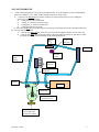
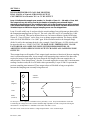
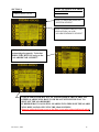
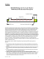
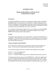
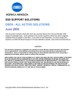
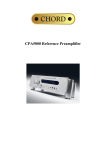
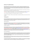
1
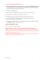
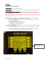
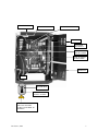
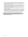
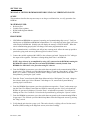
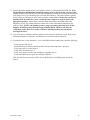
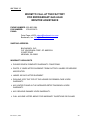
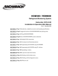
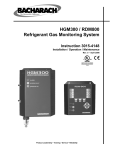
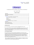
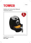
HGM300/RDM800 PREVENTATIVE MAINTENANCE AND TECHNICAL SUPPORT SECTION 1 – HGM300 CPU reset, RDM800 CPU reset, WARM UP notes and HGM300 Self Test SECTION 2 – HGM300/RDM800 Mechanical Room layout SECTION 3 – HGM300 Relay Connector SECTION 4 – Flow check procedure SECTION 5 – Clipping fault adjustment SECTION 6 – Dual loop 4-20 mA dc scrolling output SECTION 7 – HGM300 voltage check Dual loop 4-20 mA dc scrolling output SECTION 8 – Alarm silencing SECTION 9 – NDIR Sensor SECTION 10 – Gas verification test procedures A- Procedure with RDM800 B- Procedure with PC software SECTION 11 – Password protection SECTION 12 – Whom to call - Warranty File Name – Tech Support Rev June 3, 2004 1 SECTION 1 HGM300 / RDM800 TECHNICAL SUPPORT NOTES HGM300 CPU RESET Locate the white button marked “CPU reset” on the main HGM300 board (about the center of the main board). Locate the second reset button to the left of the CPU reset button. Hold the left button in, press and release the CPU reset button. There will be 5 beeps (beep/beep – beep/beep – beep). Release the left button. The monitor will now be reset A second way to reset the HGM300 CPU is to turn off power, press and hold the left hand reset button and re-apply power – 5 beeps and release button. RDM800 CPU RESET Shut off power to the RDM800, press and hold the top right adjacent button and re-apply power – 5 beeps and release button. MONITOR WILL NOT COME OUT OF “WARM UP” Try executing “SET HGM CLOCK” from RDM800. This has corrected the problem in a few instances. TO BYPASS THE WARM UP MODE Service mode – Going into and out of the service mode will perform the following functions; 1) – By pass the warm-up cycle 2) – Force a purge cycle 3) – Force a pressure check This may be helpful in analyzing problems with the monitor. HGM300 SELF TEST MODE The HGM300 refrigerant monitor has a built in self-test mode that will test the following functions: To start the self-test function, locate the left hand white button under the micro controller PCB marked “SW1”. Press and hold for two seconds then release the button. For version 1.0 and version 1.25 firmware HGM300 monitors – All lights on the HGM300 go out. The Yellow light on the RDM800 will come on after a few moments (Time out error). Each light in succession (Green, Yellow and Red) will come on. The monitor will toggle each relay (Leak, Spill, Evacuate and Fault) in succession. A signal in both channels of the dual 4-20 mA loop will simultaneously be generated (4 mA to 12 mA to 20 mA - Red light flashing). The Red light will flash during the 4-20mA test, then all lights will go out and both the HGM300 and RDM800 will return to green on only. Rev June 3, 2004 2 For version 1.40 and higher HGM300 monitors – Prior to stepping through the functions listed for version 1.0 and 1.25 the HGM300 will complete a solenoid valve check. So for V 1.40 you will hear each solenoid click before the lights sequence. The valve check starts at zone 16 and works down to the purge solenoid. A four zone monitor there is a ten seconds of silence before the valves start to click. All lights on the HGM300 go out. The Yellow light on the RDM800 will come on after a few moments (Time out error). Each light in succession (Green, Yellow and Red) will come on. The monitor will toggle each relay (Leak, Spill, Evacuate and Fault) in succession. A signal in both channels of the dual 4-20 mA loop will simultaneously be generated (4 mA to 12 mA to 20 mA - Red light flashing). The Red light will flash during the 4-20mA test, then all lights will go out, and both the HGM300 and RDM800 will return to “power on” green only. COMMON RDM800 INDICATIONS Initial start up of the HGM300/RDM800 system TIME OUT ERROR – The TIME OUT ERROR indicates that the RDM800 has not gained communication with the HGM300. Check for proper RS-485 connections in both the HGM300 and RDM800. Check for detent at each key on the RDM800. (If a key is stuck on the chassis this could lock out all functions). Locate the stuck key or keys and slip the extension back into the cut out in the chassis. CRC ERROR (Cyclical Redundancy Check) This indicates that the data from the HGM300 was corrupted in some manner. Reset the HGM300 and RDM800 to factory default settings and reset both clocks. Rev June 3, 2004 3 SECTION 2 HGM300/RDM800 Refrigerant Gas leak monitor mechanical room placement Aux. Horn/Strobe Remote Alarm Exhaust Fan Outside Hallway Sample Inlet Pickup Point Machine Room Chiller RDM800 Remote Display Module HGM300 Halogen Gas Monitor Sample Inlet Pickup Points Rev June 3, 2004 4 SECTION 3 HGM300 Relay Connector Fault NC Relay #4 NO Relay #3 COMMON NC Relay #2 NO NC NO COMMON Relay #1 3 NO 2 COMMON 1 Alarm NC Alarm COMMON Alarm Horn Strobe Neutral Main Power Line Neutral Line Aux. Power Jumper the ‘Neutral’ of the auxiliary power connector to the ‘Common’ on the relay block. Connect one end of strobe or horn to the ‘NO’ of whichever level of alarm is appropriate for application. The other end of strobe or horn is connected to a 120VAC power source, or to the ‘Line’ of the auxiliary power connector. Rev June 3, 2004 5 SECTION 4 NO FLOW CHECK PROCEDURE NO FLOW ZONE Check for air sample tube blockage. NO FLOW PURGE Check for blockage of purge line. Verify that the purge line does not exceed 100’ in length. NO FLOW ZONE AND NO FLOW PURGE Check the water trap. If full of water, drain and re-secure the petcock. If there is no water in the trap, check for a blockage in the exhaust line. Verify that the exhaust line does not exceed 100’ in length. NOTE_ Go to the diagnostic screen and view the “PRESS”, “VAC” and “AMB” values. I “PRESS” equals “VAC”; there is a blockage in the pneumatic system. If “PRESS”, “VAC” and “AMB” are all equal at about 14.0 PSIA then there is a leak in the pneumatic system. 1)– Pinch off the tubing between the water trap and in line filter. Go to the diagnostic screen on the RDM800. Observe the “PRES”, “VAC” AND “AMB” readings at the bottom of the screen. a) – If the pressure DOES NOT drop to normal vacuum levels (about 2 PSIA below pressure reading) the problem is in one of the following; 1) – Tubing from the filter to the “T” connector. 2) - Tubing from the “T” connector to pressure sensor. 3) – Tubing from “T” connector to the I/R bench. 4) – Tubing from I/R bench to the pump. b)– If the pressure DOES drop to normal vacuum levels then go to the tubing between the solenoid manifold and the water trap and pinch it closed. 1) – If the pressure DOES NOT drop to the same level as the first reading the problem is in the water trap. 2) – If the pressure DOES drop to the same reading as the first reading the problem is most likely in either the tubing around the solenoid manifolds or the solenoids themselves. Observe “PRES”, “VAC” and “AMB” readings during the check procedure Rev June 3, 2004 6 IN LINE FILTER “T” CONNECTOR PRESSURE SENSOR I/R BENCH SOLENOID MANIFOLD STEP”A” PINCH TUBING STEP “B” PINCH TUBING HERE EXHAUST PUMP WATER TRAP CHECK THAT “FLOAT” IS FREE ENSURE THAT DRAIN PETCOCK IS TIGHT (TURN CLOCKWISE TO TIGHTEN Rev June 3, 2004 7 NO FLOW PROBLEMS 1) – Pinch off the tubing between the water trap and internal filter. Go to the diagnostic screen on the RDM800. Observe the “PRES”, “VAC” AND “AMB” readings at the bottom of the screen. b) – If the pressure does not drop to normal vacuum levels (about 2 PSIA below pressure reading) the problem is in one of the following; 5) – Tubing from the filter to the bench. 6) - Tubing, “T” connector to pressure sensor. 7) – Tubing from “T” connector to I/R bench. 8) – Tubing from I/R bench to pump. b)– If the pressure does drop to normal vacuum levels then go to the tubing between the solenoid assembly and the water trap and pinch it closed. 3) – If the pressure does not drop to the same level as the first reading the problem is in the water trap. 4) – If the pressure does drop to the same reading as the first reading the problem is most likely in either the tubing around the solenoid manifolds or the solenoids themselves. In line Filter “T” connector I/R Bench Pressure sensor Step “a” pinch tubing Solenoid manifold Step “b” pinch tubing here Exhaust Pump Water Trap Check that “FLOAT” is free Ensure that the drain valve is tight (Turn clockwise to tighten) Rev June 3, 2004 8 SECTION 5 CLIPPING FAULT ADJUSTMENT Locate R-34 Gain adjust potentiometer. Adjust DETECTOR voltage using the Diagnostic screen until the voltage is 4.24 volts. If the reference voltage is properly set, the clipping fault will go away after the unit samples the next zone. Note - It may take several minutes for a voltage change to appear on the diagnostic screen due to the cycle time of the monitor from zone to zone. If the clipping fault remains, the reference voltage must be verified and corrected if needed. Locate TP1 (+) and TP2 (-) on the HGM300 main PC board (they are found to the left of R-33 the reference adjust potentiometer). Connect a voltmeter to TP1 and TP2. Use R-33 (Ref. Adj.) to adjust the reference voltage to 5.000VDC +/- 0.002. TP2 (-) TP1 (+) R33 - Reference Adjust 5.000 VDC +/- 0.002 VDC R34 - Gain Adjust Rev June 3, 2004 9 SECTION 6 HGM300 REFRIGERANT GAS LEAK MONITOR DUAL LOOP 4 to 20 mAdc SCROLLING OUTPUT CONVERTING 4 to 20 mAdc TO 1 to 5 V DC OUTPUT Loop #1 indicates the sample zone number; i.e. 5 mAdc = Zone #1 … 20 mAdc = Zone #16. The output of Loop #1 will be fixed by the number of sampling zone solenoid blocks attached to the main board. The exception to this rule is that sampling zones will be skipped if the sample tube length is set to “0” feet in the zone set up menu. This also affects the 4 to 20 mAdc output so that these skipped sampling zones are also skipped here. Loop #2 scrolls with Loop #1 and provides the actual reading of any refrigerant gas detected for the companion sampling zone in Loop #1. The scale value for Loop #2 is a nominal 0 to 1,000 ppm = 4 to 20 mAdc. This can be adjusted, however, for better resolution. On the HGM setup screen #2, “Loop #2 Factor” can be reset so as to change output resolution. The factory default value is 0.0160 MA/PPM or “0 to 1,000” ppm. If the resolution needs to be changed simply divide 16 mA by the maximum desired value; example: 16mA/500 ppm = 0.0320 which would be entered as the new “LOOP2 FACTOR”. PLEASE NOTE: THERE IS ONLY 1 LOOP FACTOR FOR ALL SAMPLING ZONES IN THE HGM300 MONITOR; I.E. ADJUSTING ONE SAMPLING ZONE OUTPUT CHANGES ALL SAMPLING ZONE OUTPUTS! These output loops scroll together. Their output signals remain as a function of the next sampling zone’s total measurement time. As an example: total measuring time consists of the draw time required to insure a fresh sample has been drawn the full length of the zone sample tube, as entered on the “Zone Setup Screen”, plus the 12 seconds required to average the 16 measurement readings. In other words, the 4 to 20 mAdc values presented by Loops #1 and #2 represent the previous sampling zone measured. These output values will be held as long as required to measure the sampling zone currently being observed. 4-20mA connector Gnd (Negativ) Wire Resistor Zone PPM (Positive) To develop a 1 to 5 V output use a 250ohm resistor, preferably ½ watt. Keep in mind that the circuit that is monitoring the voltage across the resistance should be high impedance in order to keep from affecting the measurement. An impedance of > 50Kohms will result in less than 1% error. The same circuit can be used to monitor a voltage output from the “zone” 4-20mA output Rev June 3, 2004 10 SECTION 7 HGM300 Voltage Check Z3 – 15 VDC Z2 + 15 VDC 2 RED LEDS POWER SUPPLY INDICATORS Z1 Voltage +5VDC Connector J9 Pin (-) 1 to Pin 10 (+) +5 volts DC (Communication voltage) Pin (-) 1 to Pin 8 (+) -15 volts DC Pin (-) 1 to Pin 9 (+) +15 volts DC (Bench voltages) 1 RED LED POWER SUPPLY INDICATOR 1 ORANGE LED POWER SUPPLY INDICATOR NOTE: Z1, Z2 & Z3 Red Blinking LED Indicates Communication Functioning + POS Rev June 3, 2004 NEG – 11 SECTION 8 HOW TO: SILENCE ALARMS on the HGM300 THERE ARE 4 STEPS: STEP #1: Start at this screen, the “SYSTEM SCREEN”. STEP #2: PRESS THIS BUTTON, which will take you to the “ALARM SUMMARY SCREEN”. STEP #3: Each alarm must be acknowledged separately. To do that PRESS THIS BUTTON and go to the “ALARM DETAIL SCREEN”. STEP #4: PRESS THIS BUTTON TO ACKNOWLEDGE THIS ALARM. ANY OTHER ALARMS WILL HAVE TO BE DEALT WITH IN THIS WAY TO SHUT OFF THE ALARM HORN! IF REFRIGERANT GAS IS STILL LEAKING INTO THIS ZONE THE ALARM WILL KEEP GOING OFF UNTIL THE LEAK IS FIXED! Return to either the System screen or the Zone screen after acknowledging the alarm! Rev June 3, 2004 12 SECTION 9 HGM300 Refrigerant Gas Leak Monitor NDIR Bench Measurement Description Pyroelectric Detector Sample Flow NDIR Source Dual Optical Bandwidth Filters Gas passing through the bench absorbs some I-R energy. Each of the 24 gasses in the onboard library has a very specific absorption signature defining the amount of energy any of these gasses will absorb in relation to the concentration present at the time of measurement. In order to increase accuracy and eliminate false alarms a narrow (8.1 to 9.4 uM) optical bandwidth filter is used to limit the optical spectrum to only those gasses listed in our library. All gasses outside of this bandwidth are ignored. The output voltage from the pyroelectric detector is processed to eliminate any extraneous noise, amplified, and digitized. This information is then sent to the onboard microcontroller, which analyzes and displays the data. The unit is purged automatically which brings in a clean air sample. This air sample contains no refrigerant gas, therefore, does not absorb any I-R energy. The energy measured in this purge sample is used as a reference or baseline, when calculating PPM values for actual input channels, which allows us to compensate for any changes that may occur over time in the measurement electronic circuitry, I-R source, or I-R detector. This also eliminates for field calibration of the unit. All measurements are temperature and pressure compensated to standard conditions to eliminate reading variability due to the climate or altitude of the unit. What specifically makes the HGM300 Single-Beam-Single-Wavelength NDIR measuring bench so different? 1.) We gold plate the inside of the sampling tube. Gold is virtually untarnishable so this improves the reflecting properties of the optical path, which improves overall measurement bench sensitivity and accuracy. 2.) Because the optical properties have been improved we can reduce lamp intensity thereby improving the I-R source life, which improves long-term reliability. We estimate source life to be beyond 5 years. 3.) I-R source modulation is required of all such devices. We do this electronically thereby eliminating any mechanical parts and improving long-term reliability. 4.) Sample temperature changes can directly affect short-term measurement stability. Our auto rezeroing function engages every 10 minutes or whenever the sample temperature changes by more than 0.2 deg. C, or the enclosure interior temperature changes by more than 2.0 deg. C. Thereby, improving measurement stability and accuracy, and completely eliminating the effects of samplecomponent temperature drift anywhere in the monitor. Rev June 3, 2004 13 5.) Auto zeroing or purging has other benefits. We discussed how it’s used to provide a zero base for comparison to the sample measurement. This, also, allows us to monitor and compensate for changes in I-R drive circuitry, source, bench, detector, and other electronic components. Again this all adds to long-term reliability and accuracy. 6.) Our narrow band filters limit the I-R range from 8.1 to 9.4 uM. These optical devices cannot fluctuate in any way. They eliminate interference from gasses with absorbencies outside this range. As it happens, humidity, which can absorb I-R energy and create erroneous readings, does not absorb I-R energy within this range. Our measuring bench, because of this filter, cannot measure in any other range adding to basic stability and accuracy. 7.) All measurements are pressure and temperature compensated so that there is never a question arising from local weather or altitude issues. We always provide the same information regardless of the location of our equipment. 8.) Our measurements, and this is one of the most important things we do, are a function of real time, on board calculations of Absorbance Units, based upon the Beer-Lambert Law. This provides a linear bench output, which, when coupled with our proprietary control algorithm, gives us better full-scale resolution. We do not simply measure a voltage and compare it to a value on a look up table. That method provides a logarithmic output, which has good low-end but poor high-end resolution. The bottom line is that we have taken a very simple, rugged, stable measuring bench design, and by incorporating state-of-the-art technology we’ve enhanced it into a virtual solid state, field replaceable, low cost, sensitive, accurate component. Rev June 3, 2004 14 SECTION 10A M1110AX-A TESTING HGM300 MONITORS USING GAS VERIFICATION KITS SCOPE This procedure describes the steps necessary to use the gas verification kits, to verify operation of an HGM300. MATERIALS USED • • • • Reference Gas Variable Flow regulator HGM 300 Refrigerant Monitor RDM 800 PROCEDURE 1. If HGM300 and RDM800 are connected, operating, and communicating skip to step 3. Verify on initial power up HGM300 and RDM 800 communicates. To verify this look in the upper left corner of the display on RDM 800. Initially unit will display the message “CHECK NODE”. When the unit is communicating properly this will change to the name programmed into unit. 2. After communication is verified the unit will go into warm up mode. Allow the warm up period to pass before going to the next step (Warm up period is about 15 min). 3. Connect the variable regulator (M1110BT) to the reference gas bottle. Connect the 3/16” tubing to the output of the regulator. Disconnect existing tubing from Zone 1 on HGM300. NOTE: Steps 4-9 may be accomplished by using a PC connected to the HGM300, running the HGM300 PC software. This may be convenient if HGM300 is remotely located from RDM800. See M1110AY-A for procedure using PC software. 4. From the RDM800 system menu, press the switch that corresponds to the communicating HGM to be gas tested. This will take you to the Main Setup Menu. Go into the “Setup Menu”; set the “Zone Hold ” to 15 minutes. Then Select “ReZero Mode” change to auto, and then return to the Main Setup Menu by pressing the “Quit” switch. 5. Enter the “Zones” menu from the Main Setup Menu and select “Refrigerant” for zone1, change to the reference bottle type. Select “Distance” and change to 5 ft; return to the System Menu by pressing “Quit” switch twice. 6. From the RDM800 System menu, press the switch that corresponds to “Zones” on the menu to go into the Zone View Menu. If more than one HGM is connected press the “Next” switch until the HGM to be gas tested is displayed. Press the Zone 1 switch until beep sounds. You will now be holding on Zone1 for 15 minuets. Go back to the System Menu by pressing the “System” switch. 7. From the RDM800 system menu, press the switch that corresponds to the communicating HGM to be gas tested. This will take you to the Main Setup Menu. Enter the Diagnostic screen by pressing the “Diag” switch. 8. Verify that the unit is not in a purge cycle. This can be done by verifying a flow of air into zone 1. Read the (PRES) reading in the diagnostic screen (write down reading). Rev June 3, 2004 15 9. Connect the tubing from Reference Gas regulator to Zone 1 on the manifold of HGM 300. Note: The Fault light on HGM300 may illuminate until gas starts to flow from the reference bottle to unit. The pressure should be below the original reading (if reading does not drop the unit may be in the purge cycle. If so wait until purge cycle ends then continue). Adjust the variable regulator slowly clockwise until pressure is the same as original reading. Note: You may have to block or partially block the relief valve on the variable pressure regulator in order to achieve the appropriate pressure. Allow about 1 minute to settle then read the first PPM value in the diagnostics screen. The reading should be within ±10% of the concentration indicated on the reference bottle. NOTE: The unit may go into a purge cycle during the test process. If this happens, the PPM reading will drop to approximately 0PPM. This does not affect the verification results. However in order to obtain a valid PPM reading, the unit must be drawing from zone1. 10. Close reference by adjusting variable regulator counter clockwise until fully closed. Reset zone 1 information (distance, refrigerant, zone hold time) as desired for normal operation. 11. If reading in step 9 is not within the +-10% of the PPM reference bottle please check the following: - Verify pressure from step 8 - Check that tubing is securely connected to the reference bottle and Zone 1 input port - Verify proper gas is selected (step 5) - Verify unit is in hold for zone 1 - Verify verify proper pressure from variable gas regulator (step 9) - Verify that ample time was given for readings to stabilize If the unit still does not measure within ±10% of the Reference Gas PPM, please contact the factory. Rev June 3, 2004 16 SECTION 10B M1110AY-A TESTING HGM300 MONITORS USING GAS VERIFICATION KIT AND PC SOFTWARE SCOPE This Procedure describes the use of gas verification kits with the HGM300 PC software. MATERIALS USED • • • • Reference Gas Variable Flow Regulator HGM300 Refrigerant Monitor HGM300 PC Software PROCEDURE 1. Power Up HGM300, the green led on the monitor will blink until the warm-up cycle is complete. Connect the variable regulator to the reference bottle and connect the tubing to the variable regulator. 2. Connect RS232 cable from PC to the HGM300 RS232 connector located in lower left side of the monitor. NOTE: For instructions on PC software and setup see instruction manual. 3. Launch the PC software, when the software is live you should hear a series of beeps while the PC software reads all the registers of the HGM300. 4. Verify Rezero mode is set to auto by reading the system parameter list. If not set to auto, select the “Edit Pulldown Menu” choose the “System” item from the selection list. Change the Rezero mode to auto, then press the enter key to update the setting. The program should respond with “System Data Updated”. (On version 1.0 software it is necessary to select the “HGM Pulldown Menu” and then send the setup in order to confirm the changes) 5. Select the “HGM Pulldown Menu”, and then choose the get setup item from the menu selection list. This will update the setup from the HGM300. 6. Select the “Edit Menu”, and then choose “Zones” from the menu item list. Select Zone by pressing enter key to modify the parameters for zone1. Change refrigerant to refrigerant type of the reference bottle. Change the distance parameter to 5 ft, press the enter key then press the ESC key. Wait for PC software to respond with HGM Zone data updated. NOTE: Be sure to wait for response from PC software, selecting another menu before the response is echoed will cause the communications to timeout. On version 1.0 software it is necessary to select the “HGM pulldown menu” and then send setup item in order to confirm the changes. 7. Select “HGM Menu”, then choose “Zone Hold” from the menu item selection list. Select Zone 1 by pressing the enter key, wait for the PC software to respond with Holding on Zone. 8. Select “Diagnostic Menu”, and then choose “Sensors” from the menu item list. This will display all of the diagnostic data for the HGM300. Verify that the unit is not in a purge cycle and take the pressure reading, write down reading. Rev June 3, 2004 17 9. Connect the tubing from the reference Gas regulator to Zone 1on the manifold of HGM300. NOTE: Fault light on HGM300 may illuminate until gas starts to flow from the reference bottle. Press the enter key from keyboard the sensor readings will update indicated by a beep sound from the HGM300. The pressure should be below the original readings, if not the unit is in a Purge cycle wait until purge cycle is complete then continue. Adjust the variable regulator clockwise to set the pressure to the original pressure reading from step 7 (press the enter key to update the readings). NOTE: You may have to block or partially block relief valve on variable pressure regulator in order to achieve desired pressure. Continue this until pressure readings are the same as original readings. Allow the gas to flow for 1 minute, continue to press the enter key while observing the first PPM reading (6th line) from the sensor data menu. This value will stabilize to (typically) within +-5PPM of final reading. IF a purge cycle interrupts the process, the reading will go to 0PPM, but should return to approximately the bottle value when flow returns to zone 1. The reading should be within +-10% of the value indicated on the reference bottle. 10. Close reference bottle by adjusting variable regulator counter clockwise until fully closed. Return Zone 1 parameters (length, refrigerant, hold time) to desired operating values. 11. If the reading in step 8 is not within ±10% of the PPM reference bottle please check the following: -Verify the pressure from step 8 -Check that tubing is securely connected to the reference bottle and Zone 1 input port -Verify proper gas is selected (step 5) -Verify unit is in hold for zone 1 -Verify that ample time was given for to stabilize and reading was not taken during a purge cycle If the unit still does not measure within ±10% of the reference gas PPM, please contact the factory. Rev June 3, 2004 18 SECTION 11 TO ENTER A SYSTEM PASSWORD PROTECTED OR CHANGE A PASSWORD 1) 2) 3) 4) 5) The system must be up and communicating. Press the button to the left of “HGM# 1”. When the “PASSWORD” screen appears enter “313” as the password. From the System Screen, go to the RDM SET UP Screen. In the “PASSWORD” block, enter “000” or a new password. “000” will remove password protection completely. Rev June 3, 2004 19 SECTION 12 WHOM TO CALL AT THE FACTORY FOR REFRIGERANT GAS LEAK MONITOR ASSISTANCE PHONE NUMBER: 800-850-0044 FAX NUMBER: 678/423-2479 E-MAIL: Peter Pape: x2478, [email protected] Bacharach, Inc., [email protected] SHIPPING ADDRESS: BACHARACH, INC. C/O YOKOGAWA CORP. OF AMERICA 2 DART ROAD NEWNAN, GA 30265 WARRANTY HIGHLIGHTS ¾ PLEASE REVIEW COMPLETE WARRANTY CONDITIONS. ¾ PARTS: 2 YEARS AFTER SHIPMENT FROM FACTORY UNLESS OTHERWISE NEGOTIATED. ¾ LABOR: 90 DAYS AFTER SHIPMENT. ¾ DRILLING INTO THE TOP OF THE HGM300 OR RDM800 CASE VOIDS WARRANTY. ¾ ANY WATER FOUND IN THE INFRARED DETECTING BENCH VOIDS WARRANTY. ¾ ANY OBVIOUS DAMAGE VOIDS WARRANTY. ¾ CALL ANYONE LISTED ABOVE FOR WARRANTY QUESTIONS OR CLAIMS. Rev June 3, 2004 20