1
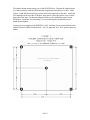
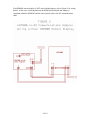
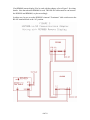
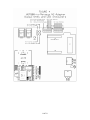
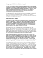
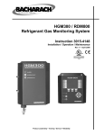
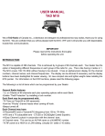
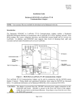
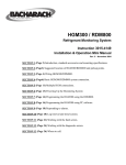
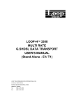
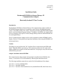
3015-4570
Revision 1.1
8/6/03
Installation Guide
Bacharach HGM300 to Johnson Metasys N2
Communications Adapter
Electrically Isolated N2 Port Version
Introduction
The Bacharach HGM300 to Johnson Metasys N2 Communcations Adapter enables an
HGM300 Refrigerant Monitor to communicate with a Metasys building management
system. Zone PPM readings, flow status, refrigerant selections, and HGM internal health
may be viewed on Metasys operator stations. In addition, each HGM zone supports three
levels of alarming (Leak, Spill, Evacuate) through Metasys and each alarm threshold can
be set through Metasys.
The N2 Communications Adapter can be used in conjunction with the RDM800 remote
display if desired. Wiring details and operation limitations when using the RDM800 will
be discussed below.
Caution
The adapter is powered from the 120V Auxiliary Power connection on the HGM main
board. When the HGM is powered up, 120V is present on the lower left corner of the
adapter within the area shown on the board silkscreen. Keep fingers away from this area
when HGM is powered!!
Adapter Installation Inside HGM300
The communications adapter board will normally be installed in the HGM300 at the
factory. It can, however, be field installed by following the instructions below.
The following installation materials are needed for field installation of the adapter:
(5) 6-32 x ¼” screws (standard finish)
(5) 6-32 x ½” threaded standoffs
(5) 6-32 x ¼” decorative black anodized screws (standard finish OK, black looks nicer)
1 of 10
The adapter board mounts on the rear of the HGM300 door. Position the adapter board
so as not to interfere with the HGM internal components when the door is shut. Mark
(Figure 1) and drill the board’s four corner holes and center hole in the door. Install the
five standoffs on the rear side of the door using the five black decorative screws on the
front side of the door. Position the adapter board over the standoffs mounted on the
HGM door. Install the five remaining 6-32 screws through the board and into the
standoffs and tighten.
Connect power wiring from the HGM300’s 120V Auxiliary Power terminal block to the
adapter board’s POWER terminal block. Use UL approved wire. Wire polarity does not
matter.
2 of 10
If an RDM800 remote display is NOT used with the adapter, refer to Figure 2 for wiring
details. In this case, all wiring between the HGM300 main board and adapter is
contained within the HGM300 and the only external cable is the N2 communications
cable.
3 of 10
If an RDM800 remote display IS to be used with the adapter, refer to Figure 3 for wiring
details. Note that when the RDM800 is used, TWO RS-485 cables must be run between
the HGM300 and RDM800, so plan accordingly.
In either case, be sure to set the HGM300’s internal “Terminator” slide switch next to the
RS-485 terminal block to the “In” position.
4 of 10
Field Hookup of N2 Communications
The “BAS BUS” (N2) RS-485 communications port on the adapter is electrically isolated
from the HGM300 and from earth ground. This prevents problems with potential
differences in “ground” between physically separate locations.
Connect the N2 ‘+’ wire to the BAS BUS N+ terminal block screw. Connect the N2 ‘-‘
wire to the BAS BUS N- terminal block screw. Connect the N2 REF wire to the BAS
BUS REF terminal block screw. Shield connection practices vary. Refer to Johnson
Controls Metasys N2 documents for Johnson-recommended practices. Options are to
hard-terminate the shield to the case, soft-terminate (through a small-value capacitor) the
shield to the case, or leave the shield floating.
If the adapter is the last device on the N2 line, the RS-485 TERM jumper just below the
BAS BUS terminal block should be installed. Otherwise leave the RS-485 TERM
jumper disconnected.
Setting HGM Communication Address On Adapter
See Figure 4 for the location of adapter dipswitches A and B.
Switches 5-8 on the adapter’s ‘A’ dipswitch are used to match the node address set on the
HGM’s address dipswitch (on HGM main board). Values from 0-15 are possible:
HGM address
----------------0
1
2
3
4
5
6
7
8
9
10
11
12
13
14
15
A5
A6
A7
A8
---------------------------------------------Off
Off
Off
Off
Off
Off
Off
On
Off
Off
On
Off
Off
Off
On
On
Off
On
Off
Off
Off
On
Off
On
Off
On
On
Off
Off
On
On
On
On
Off
Off
Off
On
Off
Off
On
On
Off
On
Off
On
Off
On
On
On
On
Off
Off
On
On
Off
On
On
On
On
Off
On
On
On
On
Since the HGM is the only node on the adapter-to-HGM interface, address 1 is normally
used. Be sure to set the same address on the adapter and the HGM main board
dipswitches.
5 of 10
6 of 10
Setting Metasys N2 Address On Communication Adapter
Switches 1-8 on the adapter’s ‘B’ dipswitch are used to set the Metasys N2 node address.
Possible addresses are 1-255. Use the following technique to set switches B1-B8:
Divide the desired N2 address by 16. Take the integer part of the result (0-15) and use
the following table to set switches B1-B4:
N2 address upper half
B1
B2
B3
B4
(N2 address lower half)
(B5)
(B6)
(B7)
(B8)
-------------------------------------------------------------0
Off
Off
Off
Off
1
Off
Off
Off
On
2
Off
Off
On
Off
3
Off
Off
On
On
4
Off
On
Off
Off
5
Off
On
Off
On
6
Off
On
On
Off
7
Off
On
On
On
8
On
Off
Off
Off
9
On
Off
Off
On
10
On
Off
On
Off
11
On
Off
On
On
12
On
On
Off
Off
13
On
On
Off
On
14
On
On
On
Off
15
On
On
On
On
Take the value 0-15 from above and multiply that times 16. Subtract the result from the
desired N2 address. This gives another number 0-15. Use this number and the table to
set switches B5-B8.
Example: Desired N2 address is 35.
35 divided by 16 gives 2.1875.
Integer part of answer is 2.
Use table entry for ‘2’ to set B1=Off, B2=Off, B3=On, B4=Off.
Multiply 2 (from above) times 16 = 32.
Subtract 32 from desired address: 35-32 = 3.
Use table entry for ‘3’ to set B5=Off, B6=Off, B7=On, B8=On.
7 of 10
Configuring the HGM300 with RDM800 or Laptop PC
The only HGM parameters that are changeable through Metasys are the alarm thresholds.
Configuring the HGM for refrigerant type and length of tubing for each zone (zero length
to disable a zone) must be done with the RDM800 remote display or a laptop PC. Refer
to the appropriate Bacharach instructions for configuring these items. HGMs are
commonly custom-configured at the factory per the customer’s needs, so field
configuring these parameters may not be necessary.
If configuring the HGM with an RDM800, the communications adapter’s presence will
not affect the standard configuration procedure. If configuring with a laptop PC,
temporarily disconnect the HGM300’s RS-485 cable from the adapter until configuration
is complete and the laptop is disconnected.
Setting up the Metasys Database
The Metasys Point Map included with this document will provide the information needed
to set up AI (analog input), BI (binary input), and ADI (internal integer) points in the
Metasys database. Additional comments are provided below to supplement the map.
The HGM can support up to 16 zones in groups of 4 zones, but a particular HGM may
not have all zones installed. There is probably no good reason to include points in the
Metasys database for zones that are not installed in the HGM.
Each monitored zone in the HGM supports three levels of alarming: Leak, Spill,
Evacuate. Since the Metasys N2 architecture does not support three different levels of
high alarming per AI point, each HGM zone is set up as THREE AI points. The first AI
point for a zone supports a Leak Alarm, the second AI point for a zone supports a Spill
Alarm, and the third AI point for a zone supports an Evacuate Alarm. All three AI points
for a zone return the same PPM reading, it’s the alarm thresholds that differ.
Alarm thresholds in PPM are set through Metasys by setting each AI point’s “High
Alarm Limit.” Each alarm threshold may be set to a value of 1-65535 PPM. Please note
that for a particular zone, the Spill threshold must be set higher than the Leak threshold,
and the Evacuate threshold must be set higher than the Spill threshold. All Metasys
warning/alarm limits other than “High Alarm Limit” are ignored. Because the HGM
samples slowly, alarm “differential” to prevent alarm chattering is not needed. Therefore
the Metasys “Differential” parameter for each AI may be written but will be ignored.
Certain HGM faults will cause various points to be marked unavailable/unreliable. For
example, a global flow fault will cause ALL AI PPM values to be marked unreliable,
whereas a flow fault on a single zone will only cause the three AI PPM values associated
with that zone to be marked unreliable. Note that any time power is cycled to the HGM,
it goes through a 15-minute warmup cycle (even if it was already warm!). During this
time, all AI PPM values will be marked unreliable. Moral of story: don’t cycle HGM
power needlessly if you would like to get valid PPM readings within the next 15 minutes!
8 of 10
There are several ADI points which can provide useful information such as type of
refrigerant programmed for each zone, number of zones actually installed in the HGM,
the number of zones in alarm, HGM operating mode, etc.
Alarm Acknowledge Options
Two alarm acknowledge options are supported—Auto Acknowledge and Network
Acknowledge.
In the Auto Acknowledge mode, the HGM will clear its alarm outputs the next time the
alarmed zone is sampled and its PPM has dropped below the alarm thresholds. No
intervention from the Metasys network is necessary.
In the Network Acknowledge mode, the HGM will never clear its alarm outputs until the
Metasys network connection has acknowledged the Change-of-State alarms reported to
Metasys. Once Metasys has acknowledged the alarm messages, the HGM will clear its
alarm outputs the next time the alarmed zone is sampled and its PPM has dropped below
the alarm thresholds. Please note that the Metasys acknowledgement is a field-level
acknowledgement that takes place automatically (typically within a few seconds). It is
not a human operator acknowledging that the alarm was seen on a console. The Metasys
acknowledgement does, however, mean that the system has caught the alarm and that it
will be reported to some higher level.
Dipswitch A1 on the adapter selects which alarm acknowledge option is used:
A1 On = Auto Acknowledge
A1 Off = Network Acknowledge
Operating Limitations When Using RDM800 Remote Display
When an RDM800 remote display is used, the N2 network will have access to the
HGM300 as long as the RDM800 is in either the SYSTEM or ZONE VIEW screen. If
the RDM800 is set to display any other screen, it will respond to polls from the N2
adapter with an HGM BUSY exception code. The N2 adapter will handle the exception
by marking most points as Unavailable and setting the Unavailable Reason point = HGM
Busy. When the RDM800 is returned to the SYSTEM or ZONE VIEW screen, normal
N2 monitoring will resume.
If the operator leaves the RDM800 in some screen other than SYSTEM or ZONE VIEW
for an extended period of time (10 minutes default), the RDM800 times out and
automatically returns to either the SYSTEM or ZONE VIEW screen. This will restore
normal N2 monitoring.
9 of 10
Communications LED Indicators
See Figure 4 for the locations of the communications LED indicators.
The communications adapter board has four LED communications status indicators
numbered 1-4. The meanings of these indicators are as follows:
LED 1 ON: Adapter is transmitting a poll/command to the HGM
LED 2 ON: Adapter is receiving a response from the HGM
LED 3 ON: Adapter is transmitting a response to Metasys N2
(because poll/command was directed to this slave)
LED 4 ON; Adapter is receiving a poll/command from Metasys N2
(directed to ANY N2 slave, not necessarily this one)
Under normal conditions, you would expect to see lots of activity on LED 4 since the N2
master is continually polling all N2 slaves on the line. LED 3 will show activity based on
how often the N2 master is polling the adapter (versus other N2 slaves on the line). If
there are few N2 slaves on the line, lots of polls will be directed to the adapter and LED 3
will blink frequently. If there are many N2 slaves, the adapter will be polled less
frequently and LED 3 will blink less frequently.
LED 1 and LED 2 will only show occasional activity. Since the refrigerant monitoring
process is fairly slow and new data is only available every 15 seconds or so, the adapter
polls the HGM at a slow rate to reduce the communications burden on the HGM main
processor.
Miscellaneous Notes
RS-485 communications wires ARE polarity sensitive. If the adapter does not
communicate on the N2 RS-485 port, try swapping the communications wires on the N+
and N- terminal block screws. The HGM port uses the same labels as the HGM main
board, so if you match the wires to the labels, polarity should not be an issue there.
If the adapter seems to not be functioning correctly, it can be restarted without restarting
the HGM simply by pressing the CPU RST button just below the “A” dipswitch. If you
restart the adapter by cycling the HGM’s power, you will have to wait for the HGM’s 15minute warmup cycle to end before PPM readings are available! If restarting the adapter
alone doesn’t help, then try cycling power to the entire HGM.
When the adapter software first starts, it attempts to establish communications with the
HGM before attempting to communicate on the N2 port. Do not be concerned after
cycling power or pressing CPU RST that no N2 activity is shown on the LEDs
immediately. The software delays about 20 seconds after a restart before attempting to
establish N2 communications.
The LEDs are driven by adapter software states, not by the RS-485 hardware. If an RS485 connection stops working in the middle of receiving a message, the RX LED may
stay on indefinitely until the connection starts working again.
10 of 10