1
W24A
active, biamped, processor
controlled loudspeaker system
active, processor controlled, bi-amped speaker system
Il lampo con la freccia inserito in un triangolo equilatero avvisa l'utilizzatore della
presenza di tensione pericolosa, senza isolamento, all'interno dell'apparecchio che
potrebbe essere sufficientemente alta da generare il rischio di scossa elettrica.
Il punto esclamativo inserito in un triangolo equilatero avvisa l'utilizzatore della
presenza di importanti istruzioni per l'utilizzo e per la manutenzione.
IMPORTANTE ! Norme di sicurezza
ATTENZIONE
Nell'interesse della propria e della altrui sicurezza, e per non
invalidare la garanzia, si raccomanda una attenta lettura di questa
sezione prima di adoperare il prodotto.
- Questo apparecchio è stato progettato e costruito per venire utilizzato
come sistema di altoparlanti con amplificatore nel contesto tipico di un
sistema di amplificazione sonora e/o di un sistema di registrazione sonora.
L'utilizzo per scopi diversi da questi non è contemplato dal costruttore, ed
avviene pertanto sotto la diretta responsabilità dell'utilizzatore/installatore.
PER EVITARE IL RISCHIO DI INCENDIO E/O DI FOLGORAZIONE:
• Non esporre il prodotto alla pioggia, non utilizzarlo in presenza di elevata
umidità o vicino all'acqua. Non lasciare penetrare all'interno dell'apparecchio
alcun liquido, né alcun oggetto solido. In caso ciò avvenga, scollegare immediatamente l'apparecchio dalla rete elettrica e rivolgersi ad un servizio di
assistenza qualificato prima di adoperarlo nuovamente.
• Prima di collegare l'apparecchio alla rete elettrica assicurarsi che la
tensione corrisponda a quella indicata sull'apparecchio stesso.
• Collegare questo apparecchio esclusivamente ad una presa di corrente
dotata di contatto di terra, rispondente alle norme di sicurezza vigenti, tramite il cavo di alimentazione in dotazione. Nel caso in cui il cavo necessiti
di sostituzione, utilizzare esclusivamente un cavo di identiche caratteristiche.
• Non appoggiare alcun oggetto sul cavo di alimentazione. Non posarlo
dove possa costituire intralcio e causare inciampo. Non schiacciarlo e non
calpestarlo.
• Installare questo apparecchio prevedendo ampio spazio circostante per
un'abbondante circolazione d'aria, necessaria al raffreddamento.
Non ostruire le aperture o le prese d'aria presenti sull'apparecchio.
• In caso di sostituzione del fusibile esterno, utilizzare esclusivamente un
fusibile di caratteristiche identiche, come riportato sull'apparecchio.
• Prima di effettuare qualsiasi operazione di collegamento, assicurarsi che
l'interruttore di accensione dell'apparecchio sia in posizione '0'.
• Prima di effettuare qualsiasi spostamento del prodotto già installato o in
funzione, rimuovere tutti i cavi di collegamento.
• Per scollegare l'apparecchio dalla rete elettrica, non tirare mai lungo il
cavo, ma afferrarlo sempre per il connettore.
W24A
ITALIANO
INDICE
Introduzione
3
__________________________________________
Descrizione
3
__________________________________________
Pannello controlli e connessioni
4
__________________________________________
Importante !!!
5-6
__________________________________________
Appendice:
12 - 18
__________________________________________
◗ Dati tecnici
13
__________________________________________
◗ Curva di risposta
14
__________________________________________
◗ Schema a blocchi
14
__________________________________________
◗ Connettori
15
__________________________________________
◗ Esempio di collegamento
16
__________________________________________
◗ Esempi di installazione
17
__________________________________________
◗ Parti di ricambio
18
__________________________________________
ATTENZIONE!
Questo apparecchio non contiene parti interne destinate all'intervento diretto da parte dell'utilizzatore. Per evitare il rischio
di incendio e/o folgorazione, non aprirlo. Per qualsiasi intervento
di manutenzione o riparazione, rivolgersi alla
Elettronica Montarbo srl e/o a personale altamente qualificato
specificamente segnalato da questa.
- Nel predisporre l'apparecchio all'utilizzo, assicurarsi che la forma e la
portata della superficie di appoggio siano idonee a sostenerlo. Nel caso si
desideri installare la cassa su di un'asta di supporto, utilizzarne una di
portata adeguata al peso del prodotto, inserendola nell'apposito adattatore.
Qualora si desideri sospendere il sistema, accertarsi che vengano
rispettate le prescrizioni riportate a pag. 5.
- Per evitare urti, calci, inciampi, riservate come luogo per l'istallazione del
prodotto un'area protetta inaccessibile a personale non qualificato.
Qualora l'apparecchio venga utilizzato in presenza di bambini e animali, si
rende necessaria una strettissima sorveglianza.
- Questo prodotto è in grado di generare pressioni acustiche molto elevate,
pericolose per la salute del sistema uditivo. Evitarne quindi l'utilizzo ad elevati livelli acustici se il pubblico si trova eccessivamente vicino al prodotto
(almeno ad 1 m di distanza).
☛ Non esporre i bambini a forti sorgenti sonore.
ITALIANO
2
active, processor controlled, bi-amped speaker system
W24A
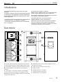
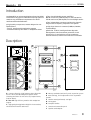
Introduzione
La grande adattabilità di questa cassa alle diverse
situazioni
di impiego consente di risolvere efficacemente ogni tipo
di installazione e di rispondere in maniera ottimale alle
diverse esigenze professionali di amplificazione e distribuzione del suono.
2 amplificatori MosFet in classe AB
800 W continui (1100 W di picco) per le frequenze basse.
250 W continui (350 W di picco) per le medio-alte.
■
2 processori indipendenti che ottimizzano la dinamica
e la risposta in frequenza del sistema.
■
■ Crossover elettronico ad elevata pendenza
(1000Hz/ 24dB per ottava, Linkwitz-Riley).
Componenti di alta qualità costruiti su nostre specifiche:
- due woofer da 12" con magnete in neodimio,
- una tromba a direttività costante con driver dinamico
da 2" in neodimio.
■
Esclusivo circuito di protezione attiva dei trasduttori
(I.P.D.M.: Intelligent Power Dynamic Management)
permette un pilotaggio ottimale, riducendo al minimo
sovraccarichi elettrici, termici e meccanici.
■
Descrizione
C
E
A
D
MADE IN ITALY BY
Montarbo
MOD.
POWER
SERIAL N.
W 24A
800+250W
PUSH
2
1
3
0
OUT
LINK
10
VOL.
0
10
H.F.
IN
CAUTION :
TO PREVENT ELECTRICAL SHOCK,
DO NOT REMOVE COVERS.
NO USER - SERVICEABLE PARTS INSIDE.
REFER SERVICING TO QUALIFIED
SERVICE PERSONNEL.
TO PREVENT RISK OF FIRE
ALWAYS REPLACE FUSES
WITH SAME TYPE AND RATINGS.
THIS APPARATUS MUST BE THE EARTHED
U S
E
F
2/WAY
PROCESSOR CONTROLLED
ACTIVE SPEAKER SYSTEM
XLR
1 GND
2
3
F
Montarbo
I
GND
FUSE F 6,3A
LIFT
I
0
POWER
POWER CONSUMPTION 1600W
230V
50/60Hz
B
H
G
B
E
L
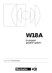
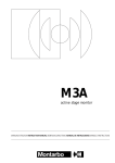
A Tromba a direttività costante (dispersione 60° H x 40° V)
con driver dinamico da 2" in neodimio (bobina mobile in piattina di alluminio, centratore in kapton, diaframma in titanio).
E Anelli ad incasso che consentono di regolare l'inclinazione della cassa sospesa.
B 2 woofer da 12" ad alta efficienza, con magnete in
neodimio.
G Tubi di accordo.
C Costruzione in multistrato di betulla ad incollaggio
fenolico, rinforzata internamente con angolari di acciaio.
I
D Binari per anelli di ancoraggio standard che consentono
la sospensione della cassa.
F Griglia in acciaio (verniciatura epossidica).
H Maniglie laterali per il trasporto.
Pannello controlli e connessioni.
L Adattatore per asta di supporto.
ITALIANO
3
active, processor controlled, bi-amped speaker system
W24A
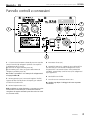
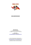
Pannello controlli e connessioni
2
PUSH
1
2
1
3
3
6
E
F
U S
7
4
5
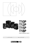
1 Il sistema acustico W24A è dotato di prese XLR maschio
(OUT) e femmina (IN) collegate in parallelo: ciò semplifica
il collegamento di più sistemi.
❚ uscita mixer ➔ ingresso W24A (presa 'IN')
❚ uscita W24A (presa 'OUT') ➔ ingresso della W24A da
collegare in parallelo (presa 'IN').
☛ Vedere "connettori" ed "esempio di collegamento"
alle pagine 15 e 16
2 Volume generale (VOL). Permette di regolare i livelli di
ingresso dei due finali di potenza incorporati, per adattarli
al livello di uscita del mixer.
4 Interruttore di rete (I/0).
5 Ground-lift (GND LIFT): scollega la massa dell’amplificatore dal telaio, pur conservando il collegamento a terra
di quest’ultimo. Consente di ridurre i ronzii prodotti dai
cosiddetti 'ground loops' (anelli di massa) nei collegamenti
di più apparecchi.
6 Portafusibile con fusibile.
7 Presa di rete con connettore Power Con®.
☛ Vedere pag. 6 per il cablaggio del cavo su questo
connettore.
3 Volume frequenze alte (H.F.).
N.B: se utilizzate un mixer Montarbo, o comunque un mixer
avente livello di uscita 0dB, per un rendimento ottimale
consigliamo di regolare entrambi questi due volumi al massimo (in senso orario).
ITALIANO
4
active, processor controlled, bi-amped speaker system
W24A
Importante !
Cura e manutenzione del prodotto:
• Posizionate la cassa lontano da fonti di calore (lampade, fari, sorgenti luminose di alta potenza, caloriferi
o qualsiasi altro oggetto che produca calore).
• Evitate di esporre la cassa alla radiazione solare
diretta, ad eccessive vibrazioni e ad urti violenti.
• Evitate l'uso ed il deposito dell'apparecchio in ambienti
polverosi o umidi: eviterete così cattivi funzionamenti e
deterioramento anticipato delle prestazioni.
• Evitate l'uso dell'apparecchio vicino a fonti di interferenze
elettromagnetiche (monitor video, cavi elettrici di alta
potenza). Ciò potrebbe compromettere la qualità audio.
• Proteggete l'apparecchio dal rovesciamento accidentale di
liquidi o sostanze di qualsiasi tipo. In particolare nelle condizioni di utilizzo tipiche, prestate la massima attenzione alla
collocazione dell'apparecchio onde evitare che il pubblico, i
musicisti, i tecnici o chicchessia possa poggiarvi sopra bicchieri,
tazze, contenitori di cibo o di bevande, posacenere o sigarette
accese.
2 - Non usare un solo accessorio per la sospensione (ad
esempio, una sola catena), ma almeno due, di portata
adeguata. In caso di rottura di uno di essi, l’altro sarà in
grado di sostenere il sistema.
3 - Non agganciare mai un diffusore a quello superiore.
Ogni diffusore deve essere agganciato ai sostegni
autonomamente.
4 - Verificare sempre che la struttura cui i diffusori sono
sospesi sia in grado di sopportarne il peso, anche in
condizioni avverse. Considerare l’effetto di altri carichi
(ad esempio, il vento nelle installazioni all’aperto).
Collegamento al mixer:
Se il mixer ha uscite bilanciate XLR, utilizzate dei normali cavi
con connettori XLR bilanciati.
Se il mixer ha uscite sbilanciate XLR e non è Montarbo, è bene
accertarsi che le uscite XLR del mixer siano sbilanciate a
norme IEC 268 e cioé: 1 = massa (GND), 2 = caldo (HOT),
3 = massa (GND).
• Non togliete la griglia di protezione dalla cassa.
☛ Vedere "connettori" ed "esempio di collegamento"
alle pagine 15 e 16.
• Per rimuovere la polvere usate un pennello o un soffio
d'aria, non usate mai detergenti, solventi o alcool.
• Utilizzare sempre solo cavi SCHERMATI (cavi di segnale) di
adeguata sezione e di buona qualità.
• Abbiate cura dei cavi di collegamento, avvolgeteli evitando
nodi e torsioni.
• Prima di effettuare i collegamenti tra casse attive e mixer
accertarsi che tutti gli interruttori di rete siano spenti (0).
In tal modo si eviteranno fastidiosi rumori e picchi di segnale
talvolta pericolosi per le casse stesse.
• Non forzate i connettori ed i comandi.
• Accertatevi che l'interruttore di rete sia in posizione
'0' (spento) prima di effettuare qualsiasi collegamento.
Collegamento in parallelo di più sistemi:
Sospensione dei diffusori
La cassa acustica W24A incorpora su entrambi i lati un
binario per anello di ancoraggio standard per la sospensione
del cabinet e sulla parte posteriore due anelli ad incasso che
ne consentono l'inclinazione secondo le necessità.
• Utilizzare sempre cavi SCHERMATI (cavi di segnale) di adeguata sezione e di buona qualità.
Collegare l’uscita (LINK OUT) della prima W24A
all’ingresso (LINK IN) della seconda, l’uscita della seconda
all’ingresso della terza ecc.
☛ Vedere "esempio di collegamento" a pagina 16.
☛ Vedere "esempi di installazione" a pagina 17.
Al fine di garantire una installazione sicura, occorre seguire
alcune precauzioni importanti:
1 - Per la sospensione, utilizzare accessori (conformi alle
nome di sicurezza applicabili nel paese di impiego) il cui
produttore ne dichiari e ne garantisca la portata.
ITALIANO
5
active, processor controlled, bi-amped speaker system
W24A
Importante !
Collegamento alla rete:
• Accertarsi che la tensione di alimentazione corrisponda a
quella indicata sul pannello (sotto la presa per il cavo di
alimentazione).
• Collegare il cavo di alimentazione ad una presa di corrente
dotata di contatto di terra di sicura efficienza. Utilizzare
solamente un cavo riportante i marchi di sicurezza applicabili
nel paese di impiego.
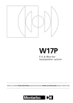
Cablaggio del cavo di alimentazione sul
connettore Power Con® (fornito con l'apparecchio):
Spelare il cavo per una lunghezza di 20 mm ed ogni singolo
filo per una lunghezza di 8 mm. Consigliamo l'utilizzo di un
cavo di alimentazione con conduttori aventi sezione di
almeno 1,5÷2mm2 (i morsetti dell'inserto possono comunque
portare un cavo con fili aventi sezione fino a 4mm2/12AWG).
20 mm
8 mm
CAVO
FILI
Infilare il cavo prima nella bussola poi nel serracavo (bianco
per un cavo con diametro 5÷11mm; nero per un cavo con
diametro 9.50÷15mm). Terminare ogni singolo filo con un
terminale ed effettuare i collegamenti dei fili sull'inserto.
TERMINALE
FILI
Tali terminazioni potranno essere serrate nei morsetti con una
chiave a brugola (1/16") oppure saldate, facendo però sempre
attenzione ai simboli: L (Line - corrispondente al filo di colore
marrone), N (Neutro - corrispondente al filo di colore azzurro)
e
(Terra - corrispondente al filo di colore giallo e verde)
che compaiono sul connettore stesso.
INSERTO
CAVO
SERRACAVO
VISTA INTERNA
BUSSOLA
N
MORSETTI
L
Effettuati i collegamenti dei fili sull'inserto infilare il cavo nel
corpo e avvitare quest'ultimo alla bussola.
CORPO
CONNETTORE CHIUSO
ITALIANO
6
active, processor controlled, bi-amped speaker system
The lighting flash with arrowhead symbol within an equilateral triangle, is intended to
alert the user to the presence of uninsulated 'dangerous voltage' within the product's
enclosure, that may be of sufficient magnitude to constitute a risk of electric shock to
humans.
The exclamation point within an equilateral triangle, is intended to alert the user to
the presence of important operating and maintenance (servicing) instructions.
IMPORTANT ! SAFETY INSTRUCTIONS
WARNING
In order to protect your own and others' safety and to avoid
invalidation of the warranty of this product, please read this section
carefully before operating this product.
This product has been designed and manufactured for being operated as
active speaker system in the applications tipical of a sound reinforcement
system or of a sound recording system. Operation for purposes and in
applications other than these has not been covered by the manufacturer
in the design of the product, and is therefore to be undertaken at end
user's and/or installer's sole risk and responsability.
TO AVOID THE RISK OF FIRE AND/OR ELECTRIC SHOCK:
• Never expose this product to rain or moisture, never use it in proximity
of water or on a wet surface. Never let any liquid, as well as any object,
enter the product. In case, immediately disconnect it from the mains supply
and refer to servicing before operating it again.
• Before connecting this product to the mains supply, always make sure
that the voltage on the mains outlet corresponds to that stated on the
product.
• This product must be connected only to a grounded mains outlet
complying to the safety regulations in force via the supplied power cable.
In case the power cable needs to be substituted, use exclusively a cable
of the same type and characteristics.
• Never place any object on the power cable. Never lay the power cable on
a walkway where one could trip over it. Never press or pinch it.
• Never install the product without providing adequate airflow to cool it.
Never obstruct the air intake openings on it.
• In case the external fuse needs replacement, substitute it only with one
of the same type and rating, as stated on the product.
• Always make sure the Power switch is in its '0' (= off) position before
doing any operation on the connections of the product.
• Before attempting to move the product after it has been installed,
remove all the connections.
• To disconnect the power cable of this product from the mains supply
never pull the cable directly. Hold the body of the plug firmly and pull it
gently from the mains supply outlet.
W24A
ENGLISH
INDEX
8
Introduction
__________________________________________
8
Description
__________________________________________
8
Control and connection panel
__________________________________________
10 - 11
Important !!!
__________________________________________
12 - 18
Appendix
__________________________________________
13
◗ Technical Specifications
__________________________________________
14
◗ Response curve
__________________________________________
14
◗ Block diagram
__________________________________________
15
◗ Connectors
__________________________________________
16
◗ Connection example
__________________________________________
17
◗ Installation examples
__________________________________________
18
◗ Spare parts
__________________________________________
CAUTION!
This product does not contain user serviceable parts.
To prevent fire and/or electrical shock, never remove its cover.
For maintenance and servicing always refer to the official
Montarbo Distributor in your Country or to qualified personnel
specifically authorised by the Distributor.
- Before placing the product on a surface of any kind, make sure that its
shape and load rating safely match the product size and weight.
When installing the speaker system on a stand, use a stable stand that will
fit in the adapter and may carry the loudspeaker weight.
If you wish to suspend the system, follow the directions at page 10.
- To avoid shocks, kicks, or whatever action, always reserve a protected
area with no access to unqualified personnel as installation site of the
product. In case the product is used near children and animals closest
supervision is necessary.
- This product can generate very high acoustic pressures which are
dangerous for the hearing system. Always avoid operation at loud levels
if anyone is excessively near to the product (at least 1 m of distance).
☛ Never expose children to high sound sources.
ENGLISH
7
active, processor controlled, bi-amped speaker system
W24A
Introduction
Two class A-B MosFet power amplifiers
800 W continuous (1100 W peak) for the bass section
250 W continuous (350 W peak) for the mid/high section.
Its adaptability to various applications allows the W24A
to be used in any type of installation ensuring optimum
results to any professional requirement for sound
reinforcement and distribution.
■
Two independent processors optimize the dynamic
range and the frequency response of the system.
■
High quality components, custom designed on our
specifications:
- two 12" woofers with neodymium magnet,
- constant directivity horn with 2" neodymium driver.
■
High slope electronic crossover (24dB/oct.,1000Hz,
Linkwitz-Riley).
■
Exclusive I.P.D.M. (Intelligent Power Dynamic
Management) active transducer protection circuit
allowing for an optimal drive of the transducers,
without electrical, thermal and mechanical overloads.
■
Description
C
E
A
D
MADE IN ITALY BY
Montarbo
MOD.
POWER
SERIAL N.
W 24A
800+250W
PUSH
2
1
3
0
OUT
LINK
10
VOL.
0
10
H.F.
IN
CAUTION :
TO PREVENT ELECTRICAL SHOCK,
DO NOT REMOVE COVERS.
NO USER - SERVICEABLE PARTS INSIDE.
REFER SERVICING TO QUALIFIED
SERVICE PERSONNEL.
TO PREVENT RISK OF FIRE
ALWAYS REPLACE FUSES
WITH SAME TYPE AND RATINGS.
THIS APPARATUS MUST BE THE EARTHED
U S
E
F
2/WAY
PROCESSOR CONTROLLED
ACTIVE SPEAKER SYSTEM
XLR
1 GND
2
3
F
Montarbo
I
GND
FUSE F 6,3A
LIFT
I
0
POWER
POWER CONSUMPTION 1600W
230V
50/60Hz
B
H
G
B
E
L
A Constant directivity, high frequency horn (dispersion
60° H x 40° V) with 2" neodymium dynamic driver
(featuring aluminum flat wire voice coil, kapton former,
titanium dome).
B Two 12" high efficiency woofers with neodymium
magnet.
C High grade phenyl-glued multiply birch construction,
reinforced with internal steel braces.
D Industry standard aluminium fly-track suspension system.
E Recessed rings, for tilt adjustment of the suspended
speaker.
F Powder coated, perforated, steel grid.
G Tuning ports.
H Transport handles.
I
Control and connection panel.
L Speaker stand adaptor.
ENGLISH
8
active, processor controlled, bi-amped speaker system
W24A
Control and connection panel
2
PUSH
1
2
1
3
3
6
E
F
U S
7
4
5
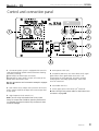
1 The W24A speaker system is equipped with XLR male
(OUT) and female (IN) parallel connected sockets allowing
easier daisy-chaining.
❚ Mixer output ➔ W24A input ('IN' socket)
❚ W24A output ('OUT' socket) ➔ input ('IN' socket) of the
W24A to be connected in series.
☛ See 'connectors' and 'connection example' at pages
15 and 16.
2 Main volume (VOL). Adjusts the input levels of the two
built-in power amplifiers to adapt them to the output level
of the mixer.
4 Mains power switch (I/ 0).
5 Ground-lift (GND LIFT): this switch allows to lift signal
ground from chassis ground (but the chassis is still
connected to the safety ground). This allows to lower
annoying hums caused by 'ground loops' when more
units are connected.
6 Fuse holder with fuse.
7 Power supply socket with Power Con® connector.
☛ See 'wiring of the power cable for the Power Con®
connector' at page 11.
3 High frequencies level control (H.F.).
N.B: if you are using a Montarbo mixer (or any mixer
having an output level of 0dB) for optimum performance
it is advisable to set both controls fully clockwise (to their
maximum settings).
ENGLISH
9
active, processor controlled, bi-amped speaker system
W24A
Important !
Product care and maintenance:
• Do not expose the enclosure to heat sources (lamps,
lights, high power light sources, radiators or other
products that produce heat).
• Never expose the enclosure to direct sunlight,
excessive vibrations or mechanical shocks.
• Never operate and store the enclosure in damp or dusty
places: this will avoid malfunctions, premature degrading of
specifications.
• Avoid using the enclosure close to strong sources of
electromagnetic interferences (e.g. video monitors, high
power electrical cabling). This may lead to degradation of
audio quality.
• Care should be taken so that objects do not fall and liquid
are not spilled into the enclosure. In public event don't let
people, musicians, technicians or anyone put glasses, cups,
ashtrays or cigarettes on the enclosure.
• Use a soft brush or a jet of air to clean the enclosure.
Do not use alcohol, solvents or detergents.
2 - Never depend on only one means of suspension
for hanging speakers (for example one chain); always
use at least two of them and make sure they are
sufficiently strong. So, if one fails the other will sustain
the load.
3 - Never hook a speaker to the one above. Each
speaker must be individually hooked to the supports.
4 - Always make sure that the truss structure intended
to support the speakers is sturdy enough to hold their
weight, even under stressful, adverse conditions.
Always consider the effect of additional loads (for
example, wind in case of outdoor installations).
Connection to the mixer:
If the mixer has XLR balanced outputs: use standard balanced
XLR connectors.
If the mixer has XLR unbalanced outputs, unless you
are using a Montarbo mixer, make sure that the XLR outputs
on the mixer are unbalanced to IEC 268 standard: 1 = GND,
2 = HOT, 3 = GND.
• Do not remove the protective grid.
☛ See 'connectors' and 'connection example' at pages
15 and 16.
• Take care of your connector cables. Make sure that they
are not damaged, knotted or twisted.
• Always use only heavy gauge, high quality SHIELDED cables
(signal cables).
• Do not force connectors and controls.
• Always make sure that the mixer and the powered
enclosures are switched off before connecting them.
This shall to avoid annoying noises and signal peaks, which
can also be dangerous for the enclosures themselves.
• Make sure the mains power switch is off ('0') before
starting any connection.
Hanging the speakers. Tips and warnings.
The W24A embodies on both cabinet sides a slide guide for
standard anchor ring to allow the loudspeaker suspension.
On its rear side, there are two recessed rings allowing tilt
adjustment.
☛ See 'installation examples' at page 17.
Parallel connection of two or more systems:
• Always use only heavy gauge, high quality SHIELDED
cables (signal cables).
Connect the first W24A’s LINK OUT to the second’s LINK IN,
the second’s LINK OUT to the third LINK IN, and so on.
☛ See 'connection example' at page 16.
In order to guarantee a safe and secure installation, observe
the following guidelines:
1 - When hanging the speakers, use only means of
suspension (in accordance with the safety regulation
valid in the country of use) having a carrying capacity
rated and guaranteed by the manufacturer.
ENGLISH
10
active, processor controlled, bi-amped speaker system
W24A
Important !
Power supply connection:
• Make sure that the mains voltage corresponds to
the voltage indicated on the rear panel, under the mains
socket.
• Use only the factory supplied mains cable or, if a different
plug style is needed, a suitable cable with
a ground connection and marked with the safety approvals
valid in the country of use.
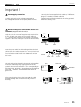
Wiring of the power cable for the Power Con®
connector (supplied with the unit):
Strip the cable for 20 mm of length and strip each wire for
8 mm of length. We suggest to use a power cable with
1,5 ÷ 2mm2 section wires (the insert terminals can however
support a cable with wires up to a section of 4mm2/12AWG).
20 mm
8 mm
WIRES
Insert the power cable into the bushing and into the chuck
(white chuck for a cable diameter of 5 ÷ 11mm; black chuck
for a cable diameter of 9.50 ÷ 15mm).
Fit a ferrule at the end of each wire and connect wires on
the insert
The wire ends can be clamped in the terminals using an Allen
wrench or soldered by always paying attention to the
symbols shown on the connector: L (Live - corresponding to
the brown wire), N (Neutral - corresponding to the light blue
wire) and
(Ground - corresponding to the yellow and
green wire).
CABLE
FERRULES FOR
STRANDS
WIRES
INSERT
CABLE
CHUCK
BUSHING
INSIDE VIEW
N
SETSCREWS
L
After connecting the wires to the insert, lead the cable
through the body and screw down the body with the
bushing.
HOUSING
POWER CON® CONNECTOR
ENGLISH
11
active, processor controlled, bi-amped speaker system
W24A
APPENDIX
__________________________________________
13
Technical Specifications
Dati tecnici
__________________________________________
14
Response curve
Curva di risposta
__________________________________________
14
Block diagram
Schema a blocchi
__________________________________________
15
Connectors
Connettori
__________________________________________
16
Connection example
Esempio di collegamento
__________________________________________
17
Installation examples
Esempi di installazione
__________________________________________
18
Spare parts
Parti di ricambio
__________________________________________
APPENDIX
12
active, processor controlled, bi-amped speaker system
W24A
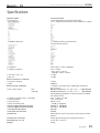
Specifications
Speaker system
• Components:
- bass frequencies
2-way bass reflex
custom designed to Montarbo specifications
2 x 12" high efficiency woofers, with neodymium magnet
Woofer Mod. 12HPL76 - 8Ω
Nominal diameter
Frequency range
Power capacity
Sensitivity
Rated impedance
Net weight
TThiele & Small Parameters
fs
Re
Qms
Qes
Qts
Vas
ho
B.l
SD
Xmax
Pe
12"
40÷2000Hz
600W
100dB
8Ω
2,7 Kg
49Hz
5,7 Ω
2,5
0,26
0,25
91dm3
4,1%
17,3Wb/m
522cm2
±4mm
700W RMS
- mid/high frequencies
2" neodymium driver coupled with a
constant directivity horn
Exponential horn (ME60)
Nominal coverage:
Cutoff frequency:
Throat diameter:
Material:
Dimensions:
Net weight:
(HxV) 60°x40°
800 Hz
50 mm (2")
cast aluminium
270x237x202 mm
2 Kg
Driver (DE950)
Throat diameter:
Nominal impedance :
D.C resistance:
Power capacity:
Sensitivity:
Frequency range:
Voice coil diameter:
winding material:
Diaphragm material
Inductance:
Flux density:
Overall diameter:
Depth:
Net weight:
50 mm (2")
8 ohms
8,3 ohms
160 Watt RMS
109,5 dB
0,5 ÷ 20kHz
75 mm
aluminum
titanium
0,14 mH
2,05 T
132 mm
85mm
2,8 kg
• Impedance
• Frequency response
• Sensitivity (1W / 1m)
• Max SPL
4 ohm (bass) / 8 ohm (mid/high)
50Hz ÷ 20kHz
- bass: 50Hz ÷1000 Hz
- mid/high: 1000Hz ÷20kHz
103 dB
134 dB
Built-in electronic crossover:
• crossover frequency
• slope
1000Hz
24dB/Oct
Built-in power amplifiers
• Max. output power
- bass
- mid-high
• Frequency response (bass + mid-high)
• Input impedance
• Input sensitivity
• Noise referred to input
• Power supply (Europe and Asia)
• Power supply (USA and Canada)
• Fuse (Europe and Asia)
• Fuse (USA and Canada)
Connections
Construction and finish
Dimensions (w x h x d)
Weight
2 MOSFET (class AB) with 2 independent processors
800 + 250 W
800 W continuous (4 ohms, @ 0,1%THD) / 1100 W peak
250 W continuous (8 ohms, @ 0,1%THD) / 350 W peak
Forced cooling provided by a thermostatically controlled
low turbolence fan.
35Hz ÷ 25kHz +0/-1dB
10KΩ (balanced)
0dB (775 mV)
- 108dB (A weighted)
230 V.A.C. 50÷60 Hz
117 V.A.C. 50÷60 Hz
F 6,3 AL
F 10 AL
Balanced male (OUT) and female (IN) XLR inputs wired in
parallel.
Phenyl-glued multiply birch; polyurethane paint
41,4 x 94,3 x 36,8 cm
46 Kg
APPENDIX
13
active, processor controlled, bi-amped speaker system
W24A
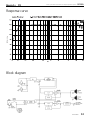
Response curve
Block diagram
APPENDIX
14
active, processor controlled, bi-amped speaker system
W24A
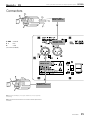
Connectors
BALANCED
MALE
XLR
CONNECTOR
▲
1 GND Ground
2+
Hot
3Cold
(IEC 268 standard)
XLR
BALANCED
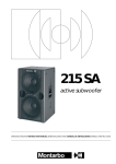
FEMALE
SOCKET
PUSH
▲
2
1
3
▲
U S
F
XLR
MALE SOCKET
2
▲
BALANCED
FEMALE
XLR
CONNECTOR
Note: the balanced LINE input can accept also unbalanced connectors (automatic
unbalancing)
Nota: L'ingresso bilanciato LINE accetta anche connettori sbilanciati (sbilanciamento
automatico).
APPENDIX
15
E
BALANCED
active, processor controlled, bi-amped speaker system
W24A
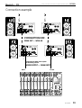
Connection example
▲
OUT ➩ IN
OUT ➩ IN
▲
PUSH
PUSH
2
1
2
1
3
3
▲
▲
U S
F
IN
IN
F
E
E
U S
➩
➩
Connecting the W24A active system
to another W24A, to another W24A...
OUT
OUT
W24A OUT ➩ W24A IN
PUSH
PUSH
2
1
2
3
1
3
▲
▲
U S
F
F
E
E
U S
IN
➩
➩
IN
Connecting the W24A active system
to the mixing console:
MIXER OUTPUT ➩ W24A INPUT
R OUT
L
OUT
AUX OUTPUTS
PHANTOM 48V D.C.
PHANTOM 48V D.C.
PHANTOM 48V D.C.
PHANTOM 48V D.C.
1
PHANTOM 48V D.C.
EFF. FT/SW
2
I
XLR OUT
3
1
3
1
3
1
2
3
1
2
MIC
3
1
2
MIC
3
1
2
3
1
2
MIC
3
1
2
MIC
3
1
2
MIC
3
1
2
3
1
2
MIC
3
1
2
MIC
3
1
2
MIC
3
1
2
3
1
2
MIC
3
1
2
MIC
3
1
2
MIC
3
1
2
3
1
2
MIC
3
1
2
MIC
3
1
2
3
1
2
MIC
2
3
1
2
(UNBAL.)
3
1
2
MIC
MIC
MIC
L
L
L
LINE
LINE
LINE
Pin 1 gnd
Pin 2 signal
Pin 3 gnd
2
mute
mute
A
C
D
0
INSERT
Sleeve gnd
Ring return
Tip send
EFF.
SEND
MIC
B
1
POWER
230V
50 60Hz
FUSE F 1A
2
XLR OUT
3
IN
IN
IN
IN
IN
IN
IN
IN
IN
IN
IN
IN
IN
IN
IN
LINE
INSERT
LINE
INSERT
LINE
INSERT
LINE
INSERT
LINE
INSERT
LINE
INSERT
LINE
INSERT
LINE
INSERT
LINE
INSERT
LINE
INSERT
LINE
INSERT
LINE
INSERT
LINE
INSERT
LINE
INSERT
LINE
INSERT
1
3
1
2
3
1
2
MIC
MIC
R
R
R
(mono)
OUT
OUT
OUT
OUT
OUT
OUT
OUT
OUT
OUT
OUT
OUT
OUT
OUT
OUT
OUT
3
1
2
MIC
(mono)
Pin 1 gnd
Pin 2 signal
Pin 3 gnd
STEREO
EFF. RET.
1
2
PHANTOM
48 V D.C.
MASTER
6 GAIN
4
2
8
6 GAIN
4
2
8
10
6 GAIN
4
2
8
10
6 GAIN
4
2
8
10
6 GAIN
4
2
8
10
6 GAIN
4
2
8
10
6 GAIN
4
2
8
10
6 GAIN
4
2
8
10
6 GAIN
4
2
8
10
6 GAIN
4
2
8
10
6 GAIN
4
2
8
10
6 GAIN
4
2
8
10
6 GAIN
4
2
8
10
6 GAIN
4
2
8
10
6 GAIN
4
2
8
10
6 GAIN
4
2
8
10
6 GAIN
4
2
8
10
6 GAIN
4
2
8
10
6 GAIN
4
2
8
10
6 GAIN
4
2
8
10
4
6 GAIN
2
8
10
4
6 GAIN
2
8
10
4
6 GAIN
2
8
10
4
6 GAIN
2
10
10
STEREO
EFF. RET.
STEREO DIGITAL
EFFECTS PROCESSORS
8
E1
HF
2
8
15
2
8
15
KHz
.75
1.6
.3
3
2
2
1.6
.3
3
2
2
8
8
8
8
3
2
2
1.6
.3
3
2
2
8
8
8
8
3
2
2
1.6
.3
3
2
2
8
8
8
8
3
2
2
1.6
.3
3
2
2
8
8
8
8
3
2
2
1.6
.3
3
2
2
8
8
8
8
3
2
2
1.6
.3
3
2
2
8
8
8
8
3
2
2
1.6
.3
3
2
2
8
8
8
8
3
2
2
1.6
.3
3
2
2
8
8
8
8
3
2
2
1.6
.3
3
2
2
8
8
3
2
2
8
1.6
.3
8
mono
PRO
mono
3
2
2
2
2
15
15
2
2
15
15
8
2
.18
HF
8
2
2
15
15
2
2
15
15
8
HF
8
2
2
15
15
2
2
15
15
8
HF
8
2
2
15
15
2
2
15
15
8
8
8
8
15 dB
15
MF
8
8
MF
8
8
MF
2
15
4
6
0
10
4
6
0
10
4
6
LF
8
2
2
15
15
4
6
0
10
4
6
0
10
4
6
8
8
8
INPUT LEVEL
INPUT LEVEL
+ 3
LF
8
2
2
15
15
4
6
0
10
4
6
0
10
4
6
8
LF
8
2
2
15
15
4
6
0
10
4
6
0
10
4
6
8
LF
8
2
2
15
15
4
6
0
10
4
6
0
10
4
6
8
LF
8
2
2
15
15
4
6
0
10
4
6
0
10
4
6
8
LF
8
2
2
15
15
4
6
0
10
4
6
0
10
4
6
8
LF
8
2
2
15
15
4
6
0
10
4
6
0
10
4
6
8
LF
8
2
2
15
15
4
6
0
10
4
6
0
10
4
6
8
LF
8
2
2
15
15
4
6
0
10
4
6
0
10
4
6
8
LF
8
2
2
15
15
4
6
0
10
4
6
0
10
4
6
8
LF
8
2
2
15
15
4
6
0
10
4
6
0
10
4
6
8
LF
8
2
2
15
15
4
6
0
10
4
6
0
10
4
6
8
LF
8
2
2
15
15
4
6
0
10
4
6
0
10
4
6
8
LF
8
2
2
15
15
4
6
0
10
4
6
0
10
4
6
8
LF
8
2
2
15
15
4
6
0
10
4
6
0
10
4
6
8
LF
8
2
2
15
15
4
6
0
10
4
6
0
10
4
6
8
LF
8
2
2
15
15
4
6
0
10
4
6
0
10
4
6
8
LF
8
2
2
15
15
4
6
0
10
4
6
0
10
4
6
8
LF
8
2
2
15
15
4
6
0
10
4
6
0
10
4
6
8
LF
8
2
2
15
15
4
6
0
10
4
6
0
10
4
6
8
LF
2
2
15
15
4
6
0
10
4
6
0
10
4
6
8
8
LF
2
2
15
15
4
6
0
10
4
6
0
10
4
6
8
8
LF
dB 0
8
2
2
15
15
4
6
0
10
4
6
0
10
4
6
8
8
2
2
8
2
B
8
2
8
0
10
4
6
2
4
6
0
10
2
6
10
6
E1
4
6
0
10
2
E2
8
6
10
E1
4
6
0
10
6
10
E1
4
6
0
10
6
10
E1
4
6
0
10
6
10
E1
4
6
0
10
6
10
E1
4
6
0
10
6
10
E1
4
6
0
10
6
10
E1
4
6
0
10
6
10
E1
4
6
0
10
6
10
E1
4
6
0
10
6
10
E1
4
6
0
10
6
10
E1
4
6
0
10
6
10
E1
4
6
0
10
6
10
E1
4
6
0
10
6
10
E1
4
6
0
10
6
10
E1
4
6
0
10
6
10
E1
dB 0
3
LF
3
4
6
0
10
6
10
E1
4
6
0
10
E1
8
4
6
0
10
6
4
6
0
10
6
10
E1
6
4
E1
6
6
10
6
E2
8
4
6
0
10
6
10
10
4
6
E1
4
E1
6
6
10
E2
8
4
6
0
10
6
10
E1
A
8
4
6
0
10
4
6
0
10
4
6
B
6
10
C
4
6
0
10
6
10
4
6
0
10
4
6
0
10
4
6
6
0
10
R
PAN
L
R
PAN
L
R
PAN
L
R
PAN
L
R
PAN
L
R
PAN
L
R
PAN
L
R
PAN
L
R
PAN
L
R
PAN
L
R
PAN
L
R
PAN
L
R
PAN
L
R
PAN
L
R
PAN
L
R
PAN
L
R
PAN
L
R
PAN
L
R
PAN
L
R
PAN
L
R
BAL
L
R
BAL
L
R
BAL
L
ON
ON
ON
ON
ON
ON
ON
ON
ON
ON
ON
ON
ON
ON
ON
ON
ON
ON
ON
ON
ON
ON
PEAK
PEAK
PEAK
PEAK
PEAK
PEAK
PEAK
PEAK
PEAK
PEAK
PEAK
PEAK
PEAK
PEAK
PEAK
PEAK
PEAK
PEAK
PEAK
PEAK
PEAK
PEAK
PEAK
R
4
6 VOL
0
10
R
6
2
10
6
10
63
125
HF
2
15
15
8
B
8
4
6
0
10
4
6
2
L
R
BAL
L
R
8
2
15
15
8
8
6
6
6
6
6
6
6
6
6
6
6
6
6
6
6
6
6
6
6
6
6
6
1K
2K
.3
3
2
D
8
2
15
10
ON
2
15
4K
8K
16K
2
2
2
15
15
8
TAPE IN VOL.
KHz
1.6
.75
2
.3
LF
2
2
8
8
15
15
PFL
LF
2
2
15
MONO
LF
8
15
4
4
6
0
10
6
2
15
8
10
0
8
6
3
3
3
3
3
3
3
3
3
3
3
3
3
3
3
3
3
3
3
3
3
3
3
3
3
3
3
3
3
3
0
0
0
0
0
0
0
0
0
0
0
0
0
0
0
0
0
0
0
0
0
0
0
0
EFF. SEND 1
0
0
0
0
0
6
6
6
6
6
6
6
6
6
6
6
6
6
6
6
6
6
6
6
6
6
6
6
6
6
2
6
6
6
6
6
9
9
9
9
9
9
9
9
9
9
9
9
9
9
9
9
9
9
9
9
9
9
9
9
9
9
9
9
9
9
9
12
12
12
12
12
12
12
12
12
12
12
12
12
12
12
12
12
12
12
12
12
12
12
12
12
12
12
12
12
12
12
12
20
20
20
20
20
20
20
20
20
20
20
20
20
20
20
20
20
20
20
20
20
20
20
20
20
20
20
20
20
20
20
20
25
25
25
25
25
25
25
25
25
25
25
25
25
25
25
25
25
25
25
25
25
25
25
25
25
25
25
25
25
25
25
25
6
8
10
8
6
6
R
0
10
0
PFL
L/R
L
9
4
6
MASTER
D
6
0
4
2
PRE
POST
PFL
C
6
PHONES
3
2
2
8
8
PFL
6
10
MF
2
15
AUX
B
4
0
2
3
2
15
8
8
FLAT
EQ
2
.18
MF
2
15
0
6
L
R
OUT
8
1.3
1.6
3
2
15
8
8
15
15
PFL
6
TAPE
Hz
HF
2
KHz
1.3
.18
8
8
8
8
MF
LF
2
15
.3
3
2
15
8
15 dB
8
15
.75
2
.18
2
8
15
HF
2
8
1.6
.75
2
.18
8
A
6
500
2
KHz
1.3
1.6
.3
HF
2
KHz
1.3
.75
C
8
0
250
IN
10
4
0
31
2
MF
ON
R
R
A
8
0
E2
L
12
9
6
3
0 dB
3
6
9
12
L
Hz
L
4
2
E1
D
3
6
9
12
DIGITAL STEREO EFFECTS
6
C
dB 0
8
C
D
E2
BAL
B
12
9
6
3
2
BAL
M
ON
A
D
8
2
L
C
8
2
8
0
10
6
10
4
8
2
8
B
8
PEAK
B
8
4
0
2
PFL
ON
523
24/2
A
8
STEREO
EFF. RET.
8
2
D
A
8
2
8
0
4
0
8
4
0
6
10
2
8
2
8
2
10
2
PFL
4
0
2
D
8
2
10
4
6
0
8
0
0
2
10
4
6 tone
4
2
flat
2
C
8
0
2
10
2
E2
8
PFL
8
2
D
8
0
8
4
0
2
PFL
8
0
2
10
2
C
8
2
B
4
0
20
6 tone
flat
A
8
2
B
8
2
D
8
2
10
4
10
4
0
8
0
0
2
8
0
2
10
2
C
A
8
2
B
8
2
D
8
2
E2
8
PFL
M
10
4
0
8
4
0
2
8
0
2
10
2
C
A
8
2
B
8
2
D
8
2
E2
8
M
10
4
0
PFL
2
C
8
0
2
10
2
8
2
D
8
2
E2
8
PFL
M
6
0
8
4
0
2
10
4
8
2
B
A
audio mixing system
8
2
10
20
4
A
8
2
C
8
0
2
10
2
B
8
2
D
8
2
E2
8
PFL
M
6
0
8
4
0
2
10
4
A
8
2
C
8
0
2
10
2
B
8
2
D
8
2
E2
8
PFL
M
6
0
8
4
0
2
10
4
A
8
2
C
8
0
2
10
2
B
8
2
D
8
2
E2
8
PFL
M
6
0
8
4
0
2
10
4
A
8
2
C
8
0
2
10
2
B
8
2
D
8
2
E2
8
PFL
M
6
0
8
4
0
2
10
4
A
8
2
C
8
0
2
10
2
B
8
2
D
8
2
E2
8
PFL
M
6
0
8
4
0
2
10
4
A
8
2
C
8
0
2
10
2
B
8
2
D
8
2
E2
8
PFL
M
6
0
8
4
0
2
10
4
A
8
2
C
8
0
2
10
2
B
8
2
D
8
2
E2
8
PFL
M
6
0
8
4
0
2
10
4
A
8
2
C
8
0
2
10
2
B
8
2
D
8
2
E2
8
PFL
M
6
0
8
4
0
2
10
4
A
8
2
C
8
0
2
10
2
B
8
2
D
8
2
E2
8
PFL
M
6
0
8
4
0
2
10
4
A
8
2
C
8
0
2
10
2
B
8
2
D
8
2
E2
8
PFL
M
6
0
8
4
0
2
10
4
A
8
2
C
8
0
2
10
2
B
8
2
D
8
2
E2
8
PFL
M
6
0
8
4
0
2
10
4
A
8
2
C
8
0
2
10
2
B
8
2
D
8
2
E2
8
PFL
M
6
0
8
4
0
2
10
4
A
8
2
C
8
0
2
10
2
B
8
2
D
8
2
E2
8
PFL
M
6
0
8
4
0
2
10
4
A
8
2
C
8
0
2
10
2
B
8
2
D
8
2
E2
8
PFL
M
6
0
8
4
0
2
10
4
A
8
2
C
8
0
2
10
2
B
8
2
D
8
2
E2
8
PFL
M
6
0
8
4
0
2
10
4
A
8
2
C
8
0
2
10
2
B
8
2
D
8
2
E2
8
PFL
M
6
0
8
4
0
2
PFL
10
4
A
8
2
C
8
0
2
10
2
B
8
2
D
8
0
8
4
0
2
10
4
A
8
2
C
8
0
2
10
0
B
8
2
D
8
2
8
2
C
A
R
2
8
2
A
10
L
OUTPUTS
Montarbo
BAL
+ 3
10
2
15
8
0
GRAMS
PROGRAM SELECTOR
MF
6 VOL
LOAD
HF
8
MF
15 dB
15
mono
E1/E2
KHz
MF
8
mono
8
15
1.3
.75
2
.18
HF
2
15
1.6
.3
15 dB
15
2
8
KHz
MF
15 dB
15
8
15
1.3
.75
2
.18
HF
2
15
KHz
MF
8
2
8
15
1.3
.75
2
.18
HF
2
15
1.6
.3
15 dB
15
2
8
KHz
MF
15 dB
15
8
15
1.3
.75
2
.18
HF
2
15
KHz
MF
8
2
8
15
1.3
.75
2
.18
HF
2
15
1.6
.3
15 dB
15
2
8
KHz
MF
15 dB
15
8
15
1.3
.75
2
.18
HF
2
15
KHz
MF
8
2
8
15
1.3
.75
2
.18
HF
2
15
1.6
.3
15 dB
15
2
8
KHz
MF
15 dB
15
8
15
1.3
.75
2
.18
HF
2
15
KHz
MF
8
2
8
15
1.3
.75
2
.18
HF
2
15
1.6
.3
15 dB
15
2
8
KHz
MF
15 dB
15
8
15
1.3
.75
2
.18
HF
2
15
KHz
MF
8
2
8
15
1.3
.75
2
.18
HF
2
15
1.6
.3
15 dB
15
2
8
KHz
MF
15 dB
15
8
15
1.3
.75
2
.18
HF
2
15
KHz
MF
8
2
8
15
1.3
.75
2
.18
HF
2
15
1.6
.3
15 dB
15
2
8
KHz
MF
15 dB
15
8
15
1.3
.75
2
.18
HF
2
15
KHz
MF
8
2
8
15
1.3
.75
2
.18
HF
2
15
1.6
.3
15 dB
15
2
8
KHz
MF
15 dB
15
8
15
1.3
.75
2
.18
HF
2
15
KHz
MF
8
2
8
15
1.3
.75
2
.18
HF
2
15
1.6
.3
15 dB
15
2
8
KHz
MF
15 dB
15
8
15
1.3
.75
2
.18
HF
2
15
KHz
MF
8
2
8
15
1.3
.75
2
.18
HF
2
8
15
1.3
1
4
2
E2
2
8
MONO
INSERT
Sleeve gnd
Ring return
Tip send
R
LINE
R
L
(mono)
LINE
LINE
(UNBAL.)
L
(mono)
2
6
6
3
0
6
EFF. SEND 2
30
30
30
30
30
30
30
30
30
30
30
30
30
30
30
30
30
30
30
30
30
30
30
30
30
30
30
30
30
30
30
30
40
40
40
40
40
40
40
40
40
40
40
40
40
40
40
40
40
40
40
40
40
40
40
40
40
40
40
40
40
40
40
40
200
600
APPENDIX
16
active, processor controlled, bi-amped speaker system
W24A
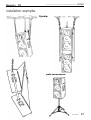
Installation examples
flyable:
pole mountable:
APPENDIX
17
active, processor controlled, bi-amped speaker system
W24A
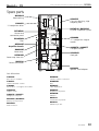
Spare parts
B01W242
Recessed ring
A300212
Constant directivity, high
frequency horn
A300602
2" neodymium driver
B01W240 / B01W241
Fly-track suspension system
D52W24A
Control and
connection panel
A300080
12" neodymium magnet
woofer
D10W24W
Filter
D52W18T
Amplifier chassis:
A088676 / A088677
Transport handle
D00W18F
Power amp.
D20W242
Steel grid
D52W18R
Power amp. heat sink
B005010
Power transformer
B010020
Speaker stand adaptor
Parti di Ricambio:
A300602:
D52W24A:
Driver da 2" in neodimio.
Pannello controlli e connessioni.
A300212:
D10W24W:
Tromba a direttività costante.
Filtro.
A300080:
D52W18T:
Woofer da 12" con magnete in neodimio.
Telaio amplificatore.
D20W242:
D00W18F:
Griglia in acciaio.
Amplificatore di potenza.
A088676 / A088677:
D52W18R:
Maniglia per il trasporto.
Radiatore.
B01W240 / B01W241:
B005010:
Binario per la sospensione.
B01W242:
Anello ad incasso.
Trasformatore di potenza.
B010020:
Adattatore per asta.
APPENDIX
18
elettronica Montarbo srl
via G. di Vittorio 13
40057 Cadriano di Granarolo
Bologna, Italy
Tel. +39. 051. 76 64 37
Fax. +39. 051. 76 52 26
E-mail: [email protected]
Internet: www.montarbo.com
Le informazioni contenute in questo manuale
sono state attentamente redatte e controllate.
Tuttavia non si assume alcuna responsabilità
per eventuali inesattezze.
Questo manuale non può contenere una
risposta a tutti i singoli problemi che possono
presentarsi durante l'installazione e l'uso
dell'apparecchio. Siamo a vostra disposizione
per fornirvi eventuali ulteriori informazioni e
consigli.
Les indications contenues en ce manuel ont
été attentivement rédigées et contrôlées.
Toutefois nous n'assumons aucune responsabilité pour des éventuelles inexactitudes.
Ce manuel ne peut contenir une réponse
pour problèmes particuliers qui pourraient se
présenter lors de l’installation et de l’usage
de l’appareil. Nous sommes à votre disposition pour d’éventuels conseils et informations
supplémentaires.
La Elettronica Montarbo srl non può essere
ritenuta responsabile per danni o incidenti a
cose o persone, causati o connessi all’utilizzazione o malfunzionamento dell’apparecchio.
Elettronica Montarbo srl ne peut être
consideré responsable des dommages causés
à des personnes ou à des objects lors de l'utilisation du produit.
The information contained in this manual has
been carefully drawn up and checked.
However no responsibility will be assumed for
any inexactitude.
This manual can not cover all the possible
contingencies which may arise during
installation and use of the product.
Should further information be desired, please
contact us or our local distributor.
Die in dieser Bedienungsanleitung enthaltenen
Hinweise wurden sorgfältig bearbeitet und
korrigiert. Es wird jedoch keine Gewähr für
die Richtigkeit der Angaben übernommen.
Diese Bedienungsanleitung kann nicht alle
Richtlinien und Probleme berücksichtigen,
welche während der Aufstellung und
Verwendung des Gerätes entstehen können.
Sollten Sie Fragen haben, wenden Sie sich
bitte an uns oder an den für Ihr Land zuständigen Importeur.
Elettronica Montarbo srl can not be
considered responsible for damages which
may be caused to people and things when
using this product.
Las informaciónes contenidas en este manual
han sidos atentamente redactas y verificadas.
De todos modos no asumimos alguna
responsabilidad de eventuales inexactitudes.
Este manual no puede contener una respuesta
a todos los problemas que pueden presentarse
durante la instalación y el uso de estos
aparatos. Estamos a vuestra disposición para
facilitar informes y consejos.
Elettronica Montarbo srl no puede ser considerada responsable de daños que puedan ser
causados a personas o cosas derivados de la
utilizaciòn del aparato.
Die Elettronica Montarbo srl haftet nicht,
für Personen- oder Sachschäden die durch die
Verwendung des Gerätes entstehen.
CARATTERISTICHE E DATI TECNICI POSSONO ESSERE MODIFICATI SENZA PREAVVISO.
SPECIFICATIONS AND FEATURES ARE SUBJECT TO CHANGE WITHOUT PRIOR NOTICE.
ÄNDERUNGEN VORBEHALTEN. LAS CARACTERISTICAS Y LOS DATOS TECNICOS PUEDEN SUFRIR MODIFICACIONES SIN PREVIO AVISO. SOUS RESERVE DE MODIFICATIONS.