1
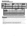
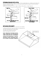
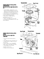
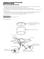
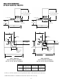
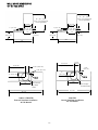
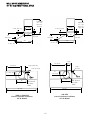
Viking Installation Guide
Designer Series
Built-In Box/Slim Traditional Hoods
Viking Range Corporation
111 Front Street
Greenwood, Mississippi 38930 USA
WARNING
NOTE: IF INSTALLING HOOD WITH WARMING SHELF
PANEL, INSTALL WARMING SHELF PANEL FIRST.
To reduce the risk of fire and electric shock, install this
rangehood only with remote blower models manufactured
by Viking- Model Numbers - DEV900/DEV1200 or
DEV1500 or integral blowers manufactured by Viking- Model
numbers DIV300, DIV440, DIV600, DIV880 or DIV1200.
NOTE: Please refer inside for specific canopy/blower
combinations.
IMPORTANT - PLEASE READ AND FOLLOW
•Before beginning, please read these instructions
completely and carefully.
•Do not remove permanently affixed labels, warnings, or
plates from the product. This may void the warranty.
•Please observe all local and national codes and
ordinances. If no local codes are applicable, wire in
accordance with the National Electrical Code, ANSI/NFPA
70-latest edition.
•Check with a qualified and trained installer or local
codes for makeup air requirement, if any.
•The installer should leave these instructions with the
consumer who should retain for local inspector’s use
and for future reference.
WARNING
TO REDUCE THE RISK OF FIRE, ELECTRICAL SHOCK,
OR INJURY TO PERSONS, RANGEHOODS MUST BE
INSTALLED WITH THE VENTILATORS THAT ARE
SPECIFIED ON THEIR CARTON INDICATING SUITABILITY
WITH THIS MODEL. OTHER VENTILATORS CANNOT BE
SUBSTITUTED.
This hood is for residential installation only and is not
designed for installation over a commercial product. Make
sure power is off at the main circuit breaker or fuse box
before making connections. To avoid risk of fire, electric
shock, or injury to persons, turn off the electricity to the
hood from the power supply before servicing or
cleaning.
WARNING
TO REDUCE THE RISK OF FIRE, ELECTRICAL SHOCK,
OR INJURY TO PERSONS, OBSERVE THE FOLLOWING:
1. Installation work and electrical wiring must be done by
qualified person(s) in accordance with all applicable
codes and standards, including fire-rated construction.
2. Sufficient air is needed for proper combustion and
exhausting of gases through the flue (chimney) of fuel
burning equipment to prevent back drafting. Follow the
heating equipment manufacturer’s guideline and safety
standards such as those published by the National Fire
Protection Association (NFPA), and the American Society
for Heating, Refrigeration and Air Conditioning
Engineers (ASHRAE), and the local code authorities.
3. When cutting or drilling into wall or ceiling, do not
damage electrical wiring and other hidden utilities.
4. Ducted fans must always be vented to the outdoors.
5. WARNING!: To reduce the risk of fire, use only metal
ductwork.
6. CAUTION!: To reduce risk of fire and to properly
exhaust air, be sure to duct air outside. Do not vent
exhaust air into spaces within walls or ceilings, or into
attics, crawl spaces, or garages.
Viking Range hoods are equipped with variable speed
controls for blowers. These units will not function with a
single speed ventilator. All Viking Range ventilator kits are
designed specifically for use with Viking Range hoods. Use
of any non-Viking Range ventilator kit will void the hood
warranty.
WARNING
TO REDUCE THE RISK OF A RANGETOP GREASE
FIRE:
1. Never leave surface units unattended at high
setting. Boilovers cause smoking and greasy
spillovers that may ignite. Heat oils slowly on
low or medium settings.
2. Always turn hood ON when cooking at high heat
or when cooking flaming foods.
3. Clean ventilating fans frequently. Grease should
not be allowed to accumulate on fan or filter.
4. Use proper pan size. Always use cookware
appropriate for the size of the surface element.
ELECTRICAL SUPPLY
Run 120 VAC electrical power cable from service
panel to installation location (see dimensions page
for exact location). See “Basic Specifications” on
page 3 for the maximum amp requirements.
CAUTION
For general ventilating use only. Do not use to exhaust
hazardous or explosive materials and vapors.
2
BASIC SPECIFICATIONS
INTERIOR AND EXTERIOR POWER HOODS
DESCRIPTION
RECOM.
CFM1
NUMBER OF
HALOGEN
LIGHTS
(int.-interior; ext.- exterior)
9” H. Wall
30”W.
36”W.
42”W.
48”W.
FILTERS
120VAC/60Hz
MAX. AMPS3
SPACERS
(Interior/Exterior)
300 int./440 int./900 ext.
300 int./440 int./900 ext./1200 ext.
440 int./900 ext./1200 ext.
2
2
2
2
2
3
N/A
1
N/A
1.7/3.2/6.6
1.7/3.2/6.6/3.9
3.2/6.6/3.9
880 int./1200 ext./1500 ext.
3
3
N/A
5.6/4.3/5.1
MODEL NUMBER
For Use with hoods:
DIV300 (interior)
DIV440 (interior)
DIV880 (interior)
CFM
1
300
440
880
RECOMMENDED
MAX. DUCT
DUCT SIZE
RUN2 (ft.)
7” round
7” round
10” round
50
50
50
DEV900 (exterior)
DEV1200 (exterior)
900
1200
10” round*
10” round
50
50
DEV1500 (exterior)
1500
10” round
75
*Must use 8” duct from canopy to ceiling - transition to 10” duct past duct cover
PROPER INSTALLATION/DUCTING IS EXTREMELY IMPORTANT TO ENSURE MAXIMUM PERFORMANCE FROM ANY
VENTILATION PRODUCT
1. •All CFMs stated are based on tests at .1 static pressure: without applying static pressure, CFM would be greatly
overstated.
2. •Duct run length is for general reference only; for longer duct runs, increase duct size and contact a qualified and trained
installer.
•Straight runs and gradual turns are best; for example, each 90o elbow is equivalent to 5-10 feet (1.52 - 3.05 m) of
straight run.
•Never use flexible duct; it creates back pressure/air turbulence and greatly reduces performance.
•Proper performance is dependent upon proper ducting; make sure that a qualified and trained installer is used.
•Check with a qualified and trained installer or local codes for makeup air requirement, if any.
3. •Max. amp rating for hoods includes recommended ventilator kit rating; all products must be hard wired direct with 2wire with ground.
3
HEIGHT OF HOOD
The bottom of the hood to should be 30” (76.2 cm) min. to 36” (91.4 cm) max. above the countertop. This
would typically result in the bottom of the hood being 66” (167.6 cm) to 72” (182.9 cm) above the floor. For best
performance results, it is recommended that the bottom of the hood be 30” (76.2 cm) to 33” (76.2 cm) above the
countertop. These dimensions provide for safe and efficient operation of the hood.
DSWB SERIES
DTWS SERIES
*Duct Cover
sold
separately
Refer to Canopy
Dimensions
Refer to Canopy
Dimensions
30” (76.2 cm)
to
36” (91.4 cm)
30” (76.2 cm)
to
36” (91.4 cm)
Countertop
Countertop
36 5/8”
(92.4 cm)
36 5/8”
(92.4 cm)
4
PREPARING FOR HOOD INSTALLATION
Plan where the ductwork will be located. See pages 11-14 for rough-in dimensions. Install proper-sized duct work,
and roof or wall cap for the type of blower you are using. Recommended hood locations for the most common
installations are shown on page 2.
Adjust your measurements for various heights of ceilings, soffits, cabinets, or ranges/rangetops.
Exterior Ventilator
Roof Cap
Duct
Duct
Duct Cover
Duct Cover
300, 440, or 880 CFM Interior Power
Typical Ductwork
900, 1200, or 1500 CFM Exterior Power
Typical Ductwork
INSTALLING HOOD CANOPY
Center the canopy and attach to wall. Secure the hood to wall with
mounting screws provided. Make sure that the mounting screws are
driven into the framing and not just the drywall.
Use additional mounting screws (and wall
anchors if necessary) in the other holes.
NOTE: BECAUSE OF THE WEIGHT OF THE
HOOD - MAKE SURE THAT THE MOUNTING
SCREWS ARE DRIVEN INTO THE FRAMING
AND NOT JUST THE DRYWALL. IT MAY BE
NECESSARY TO DRILL ADDITIONAL HOLES
IN THE CANOPY FOR PROPER ALIGNMENT.
5
Top Mounting Holes
(Soffit or duct cover)
INSTALLING THE DUCT COVER (Standard on DTWS Models)
1.
2.
3.
4.
5.
Measure from top of the canopy to ceiling and subtract 1/8” (0.3 cm) for clearance. (See Figure 1)
Place the duct cover top inside the duct cover base and lower until desired height is found. (See Figure 2)
Use the retaining nuts and bolts to fasten in place. (See Figure 3)
Slide the duct cover in place and fasten from inside canopy using the sheet metal screws provided. (See Figure 3)
For installations with ceilings above 10’ (3.05 m), refer to optional accessories.
CAUTION: To reduce the risk of scratching the duct cover top, come down in one motion to desired height. Do Not
adjust the duct cover up and down.
Item 1
Item 3
Canopy Top
B
MAX.
Figure 1
C
Item 4
Figure 3
16”
(40.6 cm)
Duct
Cover Top
Item 2
Model
DTWS3049
DTWS3649
DTWS4249
DTWS4849
Duct Cover
Base
A
12”
(30.5 cm)
Figure 2
6
“A”
12” (30.5
12” (30.5
12” (30.5
20” (50.8
cm)
cm)
cm)
cm)
“B”
33” (83.8
33” (83.8
33” (83.8
33” (83.8
cm)
cm)
cm)
cm)
“C”
21” (53.3
21” (53.3
21” (53.3
21” (53.3
cm)
cm)
cm)
cm)
INSTALLING THE DUCT COVER ( DSWB Models)
(Sold separately; required for installation - Sizes available for 8’, 9’, or 10’ ceilings)
1.
2.
3.
4.
Slide rails into openings in duct cover.
Lower duct cover into position on canopy.
Slide rails out into position in elbows.
Fasten duct cover to canopy with screws provided.
Item 2
Item 3
Item 1
Item 4
7
Threaded Studs
Top of hood
VENTILATOR KIT INSTALLATION
DIV300/DiV440
(Also see instructions supplied with ventilator
kit)
1. Attach DAMPER to VENTILATOR, as shown,
using three (3) HEX SCREWS (provided). Note:
Damper flange to be captured by screw heads.
2. Lift ventilator into position inside the hood.
3. Fasten ventilator to four (4) THREADED STUDS,
using four (4) HEX NUTS (provided).
4. Plug ventilator's POWER CORD into
RECEPTACLE inside the hood.
5. NOTE: This installatin does not use the
mounting plate and (4) additional hex nuts. They
may be discarded.
Hex
Screws
Receptacle
Damper
Ventilator
Power
Cord
Hex Nuts
Top of hood
Threaded Studs
VENTILATOR KIT INSTALLATION
DIV880
Receptacle
(Also see instructions supplied with
ventilator kit)
1. Remove front and rear filter rails from
hood.
2. Lift ventilator into position inside the hood.
3. Engage (2) tabs on ventilator into (2) slots
in top of hood.
4. Fasten ventilator to two (2) THREADED
STUDS, using two (2) HEX NUTS (provided).
5. Plug ventilator's power cord into
receptacle inside the hood.
6. Replace front and rear filter rails.
Slots
Tabs
Ventilator
Rear Filter Rail
8
Hex
Nuts
Power
Cord
Front Filter Rail
CONNECTING DUCTWORK -EXTERNAL POWER
DEV900/DEV1200/DEV1500
(Also see instructions supplied with ventilator kit)
1. Run 10” (25.4 cm) round steel ductwork from external blower to the installation location. For best performance, use the
straightest possible duct run and the fewest number of elbows. Tape all joints.
2. Run 120 VAC electrical power cable from service panel and remote blower to installation location.
3. Remove wiring box cover. Feed 6” (15.2 cm) of power cable (from service and remote blower) through the openings. See
illustration below.
4. Wire black to black, white to white, and green or bare (ground) to green ground screw (provided). Replace wiring box
cover. Make sure to connect remote wires to 2-prong male cord and service to 3-prong female cord.
5. Connect duct work to top of hood (no transition required). Tape all joints.
Ventilator Kit Contents
Supply Cord with strain relief and rough in cover
(1) #10 x 1/2 S.M.S
Green grounding screw
10” (25.4 cm) damper mounts
inside ductwork at least 3” (7.6 cm)
above canopy outlet
10” (25.4 cm) round duct
House wiring
Top of hood
Rough in box
Rough in cover
Female receptacle
blower supply (power to
blower)
Power supply cord
Male plug on back
of control panel
Blower supply cord to female
receptacle on back of control panel
9
ROOF CUTOUT
ROOF INSTALLATION
EXTERIOR-POWER VENTILATOR
203/4” (52.7 cm)
DEV900-Exterior Power Ventilator Kit (900CFM)
81/2” (21.6 cm)
(also see instructions supplied with ventilator kit)
1. Locate the blower on the rear slope of the roof. Place it
11” (27.9 cm)
REMOVE SHINGLES
dia. hole
in a location to minimize duct run. The location should
be free of obstacles (T.V. leads, electrical lines, etc.).
103/8”
Guide
Bear in mind, if the blower top is level with the roof
(26.4 cm)
Hole
peak, it will not be seen from the street. Keep this
approximate location in mind as you work from within
201/2”
the attic.
91/8”
(52.1
cm)
2. Mark a point halfway between rafters.
(23.2 cm)
3. Drill a guide hole through the roof at this point.
4. From the outside, use the guide hole as a starting
point.
71/4” (18.4 cm)
A. Use a T-square to measure 81/2” (21.6 cm) to the
left of the guide hole, then down 103/8” (26.4 cm)
11/4” (3.2 cm) dia. hole
to locate the bottom left corner of the layout.
B. Mark the rectangular cutout and remove only the
shingles in this area.
5. Mark an 11” (27.9 cm) diameter circle centered on the
29 1/2”
2”(5.1 cm)
guide hole and mark the center of the 11/4” (3.2 cm)
(74.1 cm)
diameter electrical wiring hole.
6. Cut out the roof board(s) along the 11” (27.9 cm)
diameter circle and drill a 11/4” hole as marked.
7. For flat roof installations, build a curb that will mount the
blower at a minimum pitch of 2/12. Discharge end of
the blower should be pointed away from prevailing
winds.
8. Remove roofing nails from the upper two-thirds of the
shingles around the cutout area. Carefully lift the
shingles to allow the back flashing sheet on the blower
housing to fit under them.
9. Center the blower ring in the 11” (27.9 cm) diameter
hole, making sure that the 11/4” (3.2 cm) diameter
electrical wiring hold aligns with the hole in the wiring
box.
10. Attach the blower to the roof with the six screws
provided. It is recommended that the screws be
located inside the blower housing. All six holes in the
back panel must be filled, or any moisture that may get
inside the housing could leak into the house.
11. Using a good grade of roofing cement, seal all of the
shingles around the housing and flashing sheet as well
as the mounting screw heads.
12. Bring electrical wiring through the hole in the wiring
box and secure it according to local codes.
13. Make the electrical connections with the proper
connector for the type of wiring being used. Connect
white to white, black to black, and the green or bare
wire to green.
14. Replace wiring box cover and screws. Do not pinch
wiring under the cover.
15. Check for free movement of the damper before
installing housing cover and screws.
10
16. Turn on power and check operation of the blower.
7”
(17.8 cm)
25”
(63.5 cm)
2”(5.1 cm)
Black
to
Black
Green to
Green
120 VAC
Line In
White
to
White
WALL INSTALLATION
EXTERIOR-POWER VENTILATOR
WALL CUTOUT
DEV900-Exterior-Power Ventilator Kit (900CFM)
1. Choose a position on the outside wall. Min. 24” (61.0
cm from ground may vary depending on local codes
or location. Make sure that no wall studs, pipes or
wires run through the opening area.
2. Drill a guide hole at the center of the opening area.
3. From the outside, use the guide hole as a starting
point to lay out the installation.
A. Use a T-square to measure 103/4” (27.3 cm) to the
left of the guide hole, then 127/8” (32.7 cm) to
locate the top-left corner of the layout.
B. Starting from the top -left corner, mark a 25”
(63.5 cm) by 281/2” (72.4 cm) rectangle on wall
located from guide hole.
4. Cut a rectangular hole in the siding only. Do not cut
the sheathing. Nail down all siding ends.
5. Mark an 11” (27.9 cm) diameter circle centered on the
guide hole and mark the center of the 11/4” diameter
electrical wiring hole.
6. Cut the 11” (27.9 cm) hole in the sheathing and drill
the 11/4”(3.2 cm) as marked.
7. Place a large bead of caulk on the back side of the
housing along the outer edge.
8. Center the blower ring in the 11” (27.9 cm) diameter
hole, making sure that the 11/4” (3.2 cm) diameter
electrical wiring hole aligns with the hole in the wiring
box.
9. Attach blower to the wall with the six screws
provided. It is recommended that the screws
be located inside the blower housing. All six
holes in the back panel must be filled, or any
moisture that may get inside the housing could
leak into the house.
10. Using a good grade of caulk, seal all around the
mounting screw heads.
11. Bring electrical wiring through the hole in the
wiring box and secure it according to local
codes.
12. Make the electrical connections with the proper
connector for the type of wire being used.
Connect white to white, black to black, and
green or bare wire to green.
13. Replace wiring box cover and screws. Do not
pinch wiring under cover.
14. Check for free movement of the damper before
installing housing cover and screws.
15. Turn on power and check operation of the blower.
16. Top and side flanges of the back plate may be
covered with trim strips. Do not block grill opening at
bottom with trim. It will adversely affect performance
of the blower.
11
25” (63.5 cm)
103/4”
(27.3 cm)
11” (27.9 cm)
dia. hole
12 7/8”
(32.7 cm)
Guide
Hole
91/8”
(23.2 cm)
28 1/4”
(71.8 cm)
71/4” (18.4 cm)
11/4” (3.2 cm)
Dia. Hole
Black
to
Black
Green to
Green
120 VAC
Line In
White
to
White
ROOF INSTALLATION
EXTERIOR-POWER VENTILATOR
11/4” (3.2
ROOF CUTOUT
Exterior Power Ventilator
B
(also see instructions supplied with ventilator kit)
1. Locate the blower on the rear slope of the roof. Place
it in a location to minimize duct run. The location
REMOVE
should be free of obstacles (T.V. leads, electrical lines,
SHINGLES
11
12 /16”
etc.). Bear in mind, if the blower top is level with the
(32.2 cm)
roof peak, it will not be seen from the street. Keep
this approximate location in mind as you work from
within the attic.
2. Mark a point halfway between rafters.
3. Drill a guide hole through the roof at this point.
4. From the outside, use the guide hole as a starting
point to lay out the installation.
C
A. Use a T-square to measure 913/16” (24.9 cm) to
the left of the guide hole, then 1211/16” (32.2 cm)
to locate the top-left corner of the layout.
B. Starting from the top-left corner, mark the
rectangular cutout and remove only the shingles in
this area.
291/2”
5. Mark an 11” (27.9 cm) diameter hole centered on the
(74.9 cm)
guide hole. Mark the center of the 11/4” (3.2 cm)
diameter electrical wiring hole.
6. Cut out the roof board(s) along the 11” (27.9 cm)
diameter circle and drill a 11/4” hole as marked.
7. For flat roof installations, build a curb that will mount
the blower at a minimum pitch of 2/12. Discharge
end of the blower should be pointed away from
prevailing winds.
8. Remove roofing nails from the shingles around the
22”
top and sides of the cutout area only. Carefully lift
(55.9 cm)
the shingles to allow the back flashing sheet on the
blower housing to fit under them.
A
9. Center the blower ring in the 11” (27.9 cm) diameter
DEV1200
18”
hole, making sure that the 1 ¼” (3.2 cm) diameter
(45.7 cm)
electrical wiring hold aligns with the hole in the wiring DEV1500
21”
box.
(53.3 cm)
10. Attach the blower to the roof with the six screws
provided. It is recommended that the screws be
located inside the blower housing. All six holes in the
back panel must be filled, or any moisture that may
get inside the housing could leak into the house.
Ground to
11. Using a good grade of roofing cement, seal all of the
grounding
shingles around the housing and flashing sheet as
screw
well as the mounting screw heads.
12. Bring electrical wiring through the hole in the wiring
box and secure it according to local codes.
13. Make the electrical connections with the proper
connector for the type of wiring being used.
Connect white to white, black to black, and the green
or bare wire to green.
14. Replace wiring box cover and screws. Do not pinch
wiring under the cover.
15. Check for free movement of the damper before
installing housing cover and screws.
16. Turn on power and check operation of the blower. 12
cm) dia. hole
20 1/2”
(52.1 cm)
11” (27.9 cm)
dia. hole
A
2” (5.1 cm)
7”
(17.8 cm)
2” (5.1 cm)
B
C
15”
9 13/16’
(38.1 cm) (24.9 cm)
18”
12 5/8”
(45.7 cm) (32.1 cm)
D
22”
(55.9 cm)
25”
(63.5 cm)
Black to
Black
120 VAC
Line In
White
to Blue
WALL CUTOUT
WALL INSTALLATION
EXTERIOR-POWER VENTILATOR
17” (43.2 cm)
Exterior Power Ventilator Kit
1. Choose a position on the outside wall. Min. 24” (61.0 cm
from ground may vary depending on local codes or
location. Make sure that no wall studs, pipes or wires run
1411/16
through the opening area.
(37.3 cm)
2. From inside, mark and drill a guide hole at the center of
the opening area.
3. From the outside, use the guide hole as a starting point to
lay out the installation.
A. Use a T-square to measure 1113/16” (30.0 cm) to the left
of the guide hole, then 1411/16” (37.3 cm) to locate the
top-left corner of the layout.
B. Starting from the top-left corner, mark a 22” (55.9 cm) by
291/2” (74.9 cm) rectangle on wall located from guide
hole.
4. Cut a rectangular hole in the siding only. Do not cut the
sheathing. Nail down all siding ends.
5. Mark an 11” (27.9 cm) diameter circle centered on the guide
DEV1200
hole and mark the center of the 11/4” diameter electrical
wiring hole.
DEV1500
6. Cut the 11” (27.9 cm) hole in the sheathing and drill the
11/4”(3.2 cm) as marked.
7. Place a large bead of caulk on the back side of the housing
along the outer edge.
8. Center the blower ring in the 11” (27.9 cm) diameter hole,
making sure that the 11/4” (3.2 cm) diameter electrical wiring
hole aligns with the hole in the wiring box.
9. Attach blower to the wall with the six screws provided. All
six holes in the back panel must be filled, or any moisture
that may get inside the housing could leak into the house.
10. Using a good grade of caulk, seal all around the mounting
screw heads.
11. Bring electrical wiring through the hole in the wiring box and
secure it according to local codes.
12. Make the electrical connections with the proper connector for
the type of wire being used. Connect white to blue, black to
black, and green or bare wire to grounding screw.
13. Replace wiring box cover and screws. Do not pinch wiring
under cover.
14. Check for free movement of the damper before installing
housing cover and screws.
15. Turn on power and check operation of the blower.
16. Top and side flanges of the back plate may be covered with
trim strips. Do not block grill opening at bottom with trim.
It will adversely affect performance of the blower.
3”
11/4” (3.2 cm)
dia. hole
(7.6 cm)
29 1/2”
(74.9 cm)
C
11”
(27.9 cm)
dia. hole
A
A
B
C
22”
(55.9 cm)
25”
(63.5 cm)
17”
(43.2 cm)
20”
(50.8 cm)
11 13/16”
(30.0 cm)
14 5/8”
(37.2 cm)
Ground to
grounding
screw
Black to
Black
120 VAC
Line In
White to
Blue
Spacer
(36” only)
FILTER INSTALLATION
Number of mesh filters will vary by model.
Only the 36"W. models have one spacer located
between the mesh filters
Wall Hoods - 30”W., 36”W., .
- 2 filters per unit
42” W, 48”W.
- 3 filters per unit
Mesh Filters
13
DEV1200
DEV1500
EXTERIOR VENTILATOR DIMENSIONS
Opening for wiring
DEV900
10” Dia.
18”
45.7 cm)
3”
(7.
6c
m)
1
29 /2”
(74.9 cm)
203/4” (52.7 cm)
5”
(12.7 cm)
281/4”
(71.8 cm)
1
10 /8”
25.7 cm
14 13/16”
(37.6 cm)
241/2”
(62.2 cm)
151/2”
(39.4 cm)
6 1/4
”
(15.9
cm)
10”
(25.4 cm)
Dia.
11 13/16”
(30.0 cm)
Opening for
wiring
14”
(35.6 cm)
3 1/2”
(8.9 cm)
243/4”
(62.9 cm)
1
22 /8”
(56.2 cm)
22”
55.9 cm)
43/4”
(12.1 cm)
DEV1200
Flashing
DEV1500
WIRING DIAGRAM
EXTERIOR VENTILATOR
14
Flashing
A
B
18”
22”
(45.7 cm) (55.9 cm)
21”
25”
(53.3 cm) (55.9 cm)
WALL HOOD DIMENSIONS
30” W./36” W./42” W. BOX STYLE
21”, 33”, or 44”
Duct Cover Required
(Sold separately)
21”, 33”, or 44”
Duct Cover Required
(Sold separately)
10 3/4”
(27.3 cm)
1” (2.5 cm)
12”
(30.5 cm)
9”
(22.9 cm)
10 3/4”
(27.3 cm)
1” (2.5 cm)
12”
(30.5 cm)
9”
(22.9 cm)
3 1/8”
(7.9 cm)
3 1/8”
(7.9 cm)
24”
(61.0 cm)
24”
(61.0 cm)
B
B
5 9/16”
(14.3 cm)
5 9/16”
(14.3 cm)
1 1/8”
(2.9 cm)
1 1/8”
(2.9 cm)
5 1/8”
(13.0 cm)
5 1/8”
(13.0 cm)
120 V
120 V
11”
(27.9 cm)
24”
(61.0 cm)
11”
(27.9 cm)
8” Round
for Vent
Duct*
7” Round
for Vent
Duct
A
A
300 or 440 CFM**
Internal Ventilator Installation
30” W., 36” W., and 42” W. Models
900 or 1200 CFM
External Ventilator Installation
30” W., 36” W., and 42” W. Models
Dim.
A
B
30” W.
29 7/8”
(75.9 cm)
15 3/4”
(40.0 cm)
36” W.
35 7/8”
(91.1 cm)
18 3/4”
(47.6 cm)
42” W.
41 7/8”
(106.4 cm)
21 3/4”
(55.2 cm)
*8” Dia. to 10” Dia. transition must be purchased locally. Install transition past duct cover.
**300 CFM ventilator for installation with 30” W. and 36” W. hoods only.
15
WALL HOOD DIMENSIONS
48” W. BOX STYLE
21”, 33”, or 44”
Duct Cover Required
(Sold separately)
21”, 33”, or 44”
Duct Cover Required
(Sold separately)
10 3/4”
(27.3 cm)
1” (2.5 cm)
1” (2.5 cm)
12”
(30.5 cm)
9”
(22.9 cm)
10 3/4”
(27.3 cm)
3 1/8”
(7.9 cm)
12”
(30.5 cm)
9”
(22.9 cm)
3 1/8”
(7.9 cm)
24”
(61.0 cm)
24”
(61.0 cm)
7 7/8”
23 15/16”
(60.1 cm)
23 15/16”
(60.1 cm)
7 7/8” (20.0 cm)
(20.0 cm)
1 1/8”
(2.9 cm)
1 1/8” (2.9 cm)
6”
(15.2 cm)
6” (15.2 cm)
120 V
120 V
19”
(48.3 cm)
19”
(48.3 cm)
10” Round
for Vent
Duct
10” Round
for Vent Duct
47 7/8”
(121.6 cm)
47 7/8”
(121.6 cm)
880 CFM
Internal Ventilator Installation
48” W. Models
1200 or 1500 CFM
External Ventilator Installation
48” W. Models
16
WALL HOOD DIMENSIONS
30” W./36” W./42” W. SLIM TRADITIONAL STYLE
Adjustable
10 3/4”
(27.3 cm)
3 1/8” (7.9 cm)
Adjustable
21” - 33”
(53.3 cm 1”
(2.5 cm) 83.8 cm)
12”
(30.5 cm)
9”
(22.9 cm)
12”
(30.5 cm)
9”
(22.9 cm)
24”
(61.0 cm)
2” (5.1 cm)
10 3/4”
(27.3 cm)
3 1/8” (7.9 cm)
21” - 33”
1”
(53.3 cm (2.5 cm) 83.8 cm)
24”
(61.0 cm)
2” (5.1 cm)
B
B
5 9/16”
(14.3 cm)
5 9/16”
(14.3 cm)
1 1/8”
(2.9 cm)
1 1/8”
(2.9 cm)
5 1/8”
(13.0 cm)
5 1/8”
(13.0 cm)
120 V
120 V
11”
(27.9 cm)
24”
(61.0 cm)
11”
(27.9 cm)
8” Round
for Vent
Duct*
7” Round
for Vent
Duct
A
A
300 or 440 CFM**
Internal Ventilator Installation
30” W., 36” W., and 42” W. Models
900 or 1200 CFM
External Ventilator Installation
30” W., 36” W., and 42” W. Models
Dim.
A
B
30” W.
29 7/8”
(75.9 cm)
15 3/4”
(40.0 cm)
36” W.
35 7/8”
(91.1 cm)
18 3/4”
(47.6 cm)
42” W.
41 7/8”
(106.4 cm)
21 3/4”
(55.2 cm)
*8” Dia. to 10” Dia. transition must be purchased locally. Install transition past duct cover.
**300 CFM ventilator for installation with 30” W. and 36” W. hoods only.
17
WALL HOOD DIMENSIONS
48” W. SLIM TRADITIONAL STYLE
Adjustable
21” - 33”
(53.3 cm 83.8 cm)
10 3/4”
(27.3 cm)
3 1/8” (7.9 cm)
3 1/8” (7.9 cm)
12”
(30.5 cm)
9”
(22.9 cm)
2” (5.1 cm)
1”
(2.5 cm)
10 3/4”
(27.3 cm)
12”
(30.5 cm)
9”
(22.9 cm)
24”
(61.0 cm)
Adjustable
21” - 33”
(53.3 cm 83.8 cm)
2” (5.1 cm)
1”
(2.5 cm)
24”
(61.0 cm)
7 7/8”
23 15/16”
(60.1 cm)
23 15/16”
(60.1 cm)
7 7/8” (20.0 cm)
(20.0 cm)
1 1/8”
(2.9 cm)
1 1/8” (2.9 cm)
6”
(15.2 cm)
6” (15.2 cm)
120 V
120 V
19”
(48.3 cm)
19”
(48.3 cm)
10” Round
for Vent
Duct
10” Round
for Vent
Duct
47 7/8”
(121.6 cm)
47 7/8”
(121.6 cm)
880 CFM
Internal Ventilator Installation
48” W. Models
1200 or 1500 CFM
External Ventilator Installation
48” W. Models
18
WIRING DIAGRAM
BUILT-IN DESIGNER HOODS
REFER ONLY TO FEATURES EQUIPPED WITH THIS UNIT.
19
VIKING RANGE CORPORATION
111 Front Street
Greenwood, Mississippi 38930 USA
(662) 455-1200
For product information
call 1-888-VIKING1 (845-4641)
or visit the Viking Web site at
vikingrange.com
F20141H
(PS1005VR)