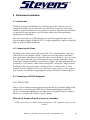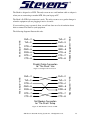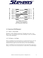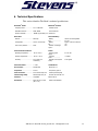
1
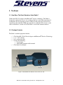
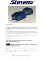
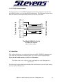
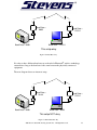
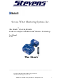
Serial Port Adapter with Bluetooth® Wireless Technology
User Manual
Ver 1.27
_____________________________________________________________
Copyright 2004 Stevens Water Monitoring Systems, Inc.
12067 NE Glenn Widing Drive, Suite 106
2004 Stevens Water Monitoring Systems Inc. All Rights Reserved.
1
Portland, Oregon 97220
USA
Tel 503-445-8000
Fax 503-445-8100
www.stevenswater.com
The contents of this document may be changed by Stevens Water Monitoring Systems, Inc.
(”Stevens”) without prior notice and do not constitute and binding undertakings from Stevens.
Stevens is not responsible under any circumstance for direct, unexpected damage or consequent
damage that is caused by this document.
All rights reserved.
Release: 0408
Document version: 1.27
Document number: B-232-05
Printed in USA
Stevens Water Monitoring Systems, Inc. is an Adopter Member of the Bluetooth® Special
Interest Group (SIG).
Trademarks
Registered trademarks from other companies are: The Bluetooth® word mark and logos are
owned by the Bluetooth SIG, Inc. and any use of such marks by Stevens Water Monitoring
Systems, Inc. is under license. Microsoft, Windows, Windows NT, Windows 2000, Windows
CE, Windows ME, Windows XP are registered trademarks from Microsoft Corporation. Other
trademarks and trade names are those of their respective owners.
_____________________________________________________________
Contents
2004 Stevens Water Monitoring Systems Inc. All Rights Reserved.
2
_____________________________________________________________
1.
INTRODUCTION.................................................................................................................. 5
1.1
1.2
WHAT IS “THE SHARK” WITH BLUETOOTH® WIRELESS TECHNOLOGY? ........................ 5
SUMMARY OF FEATURES ...................................................................................................... 5
2.
THE SHARK .......................................................................................................................... 7
2.1
2.2
2.3
2.4
2.5
2.6
2.7
2.7.1
2.7.2
2.7.3
3.
HOW DOES THE SHARK EMULATE A SERIAL CABLE?....................................................... 7
PACKAGE CONTENTS............................................................................................................ 7
CONNECTORS ........................................................................................................................ 8
SWITCHES .............................................................................................................................. 8
LED INDICATORS ................................................................................................................. 9
EXTERNAL POWER JACK ................................................................................................... 10
INTERNAL BATTERY ........................................................................................................... 10
BATTERY USE DURATION ................................................................................................. 10
RECHARGING THE BATTERY ............................................................................................. 10
USING A COM PORT FOR CHARGING ................................................................................ 11
SETTING UP THE SHARK ............................................................................................... 12
3.1 INTRODUCTION ................................................................................................................... 12
3.2 GETTING STARTED ............................................................................................................. 12
3.2.1 INSTALLING SHARK CONFIG TO CHANGE THE DEFAULT SETTING IN SECTION 3.1............ 12
3.2.2 CONNECTING THE SHARK TO YOUR PC FOR SHARK CONFIG ............................................ 13
3.3 USING SHARK CONFIG ......................................................................................................... 13
3.3.1 COMM SETTINGS ............................................................................................................... 13
3.3.2 THE SHARK SETTINGS ....................................................................................................... 15
3.3.3 DEVICE DISCOVERY .......................................................................................................... 17
3.3.3.1 Device Discovery Example............................................................................................ 18
3.3.3.1.1 Searching..................................................................................................................... 18
3.3.3.1.2 Connecting .................................................................................................................. 21
3.4 USING SHARK CONFIG OVER A LINK USING BLUETOOTH® TECHNOLOGY ...................... 23
4.
PROFESSIONAL INSTALLATION ................................................................................. 25
4.1
4.2
4.3
4.3.1
4.4
4.4.1
4.4.2
4.4.3
4.5
4.6
4.7
INTRODUCTION ................................................................................................................... 25
CONNECTING THE POWER ................................................................................................. 25
CONNECTING TO RS-232 EQUIPMENT .............................................................................. 25
DTE VS. DCE .................................................................................................................... 25
CONNECTING TO RS485 EQUIPMENT ................................................................................ 27
2-WIRE VS. 4-WIRE RS485 ............................................................................................... 27
FULL-DUPLEX VS. HALF-DUPLEX ..................................................................................... 27
RS485 INTERFACE ADAPTER ............................................................................................ 28
BAUD RATE ......................................................................................................................... 28
FLOW CONTROL ................................................................................................................. 30
THE SHARK RANGE AND ANTENNA SELECTION ............................................................... 30
2004 Stevens Water Monitoring Systems Inc. All Rights Reserved.
3
5.
TROUBLESHOOTING ...................................................................................................... 32
6.
TECHNICAL SPECIFICATIONS..................................................................................... 35
7.
APPENDIX ........................................................................................................................... 36
7.1
7.2
7.3
7.3.1
7.3.2
7.4
7.4.1
7.4.2
7.4.3
7.4.4
7.5
WHAT IS BLUETOOTH®?..................................................................................................... 36
WHY IS IT CALLED BLUETOOTH®? .................................................................................... 36
CERTIFICATION INFORMATION ......................................................................................... 37
COMPLIANCE ..................................................................................................................... 37
TYPE APPROVAL ............................................................................................................... 37
ACCESSORY ITEMS ............................................................................................................. 37
ANTENNA .......................................................................................................................... 37
RS-232 TO 2-WIRE RS485 ADAPTER ................................................................................ 37
RS485 4-WIRE TO RS485 2-WIRE ADAPTER .................................................................... 38
90-DEGREE D-SUB 9-PIN ADAPTER ................................................................................. 38
GLOSSARY OF TERMS ......................................................................................................... 38
2004 Stevens Water Monitoring Systems Inc. All Rights Reserved.
4
1. Introduction
Thank you for purchasing The Shark RS-232/485 Serial Adapter with Bluetooth®
wireless technology.
The Shark is a class 1 Bluetooth® SIG qualified radio. The class 1 radio combined with
an external antenna attachment maximizes the communication range between other
Bluetooth® wireless enabled devices. Line-of-sight connection is not required in order to
establish communications.
In addition to providing durability and flexibility, The Shark RS 232/485 Adapter with
Bluetooth® wireless technology is designed for ease of use and is preconfigured to
operate with most applications without any setup or configuration procedures. This
manual enables you to quickly get started by explaining the operations of The Shark, and
provides the information to customize your communication settings and explain how to
establish secure communications.
1.1 What is “The Shark” with Bluetooth® Wireless Technology?
The Shark is a Bluetooth® wireless technology serial cable replacement product designed
specifically for the industrial market and environmental monitoring applications. Its
robust design will handle many harsh environments and wide temperature extremes. It
uses the Bluetooth® SPP (serial port profile) protocol to replace RS-232 or RS485 cables,
whether indoor or outdoor.
Once connected, the Shark can communicate with any Bluetooth® wireless enabled
device such as other serial port adapters that use Bluetooth® wireless technology, PDA’s,
laptops, industrial equipment, data loggers and more. The Shark is preconfigured to
accept connections from other Bluetooth® wireless enabled devices in what is known as
“Slave” mode or “Server” mode. The user can configure The Shark to initiate connection
to other Bluetooth® wireless enabled devices, defined as “Master” mode or “Client”
mode.
In most applications, The Shark communicates with one Bluetooth® wireless enabled
device at a time.
1.2 Summary of Features
The following is a summary of The Shark’s features:
RS-232 and RS485 serial cable emulation
Class 1 Bluetooth® SIG Qualified radio (100 meter range)
Bluetooth® SIG Certified Compliant
External RF Antenna connector for flexible and optimal installation
Range of >100 meters possible with alternative specified antenna setup
2004 Stevens Water Monitoring Systems Inc. All Rights Reserved.
5
Default baud rate 9600 bps – configurable from 100 to 115,200 bps
RS485 hardware compatible – full duplex
9-pin male D-SUB connector, DTE
Configurable in slave mode or master mode
Blue LED gives instant status of connection to other Bluetooth® wireless enabled
devices
Switchable external power LED for conserving internal battery drain
Internal battery trickle-charging from PC or Laptop COM port
Low power drain; <5mA in slave mode
2004 Stevens Water Monitoring Systems Inc. All Rights Reserved.
6
2. The Shark
2.1 How Does The Shark Emulate a Serial Cable?
Unlike other RS-232 Adapters with Bluetooth® wireless technology, The Shark is
designed to emulate the behavior of a serial port that has a serial cable connection. It
accomplishes this by triggering an active COM port at the other end of the wireless
connection at the moment a COM port connection is established. This is how a serial
cable would behave, and this is how The Shark’s serial cable emulation behaves.
2.2 Package Contents
The Shark’s standard equipment includes:
•
•
•
•
•
1- The Shark RS-232/485 Serial Adapter with Bluetooth® Wireless Technology
1- 1 ½” “stub” antenna
1- 6-ft. power plug cable
1- Setup CD Containing:
o Shark Config
o Adobe PDF document of this manual
1- The Shark User Manual
Figure 1: The Shark RS-232 / RS485 Connector & Power Jack
2004 Stevens Water Monitoring Systems Inc. All Rights Reserved.
7
Figure 2: The Shark LED’s RF Connector, DIP Switches and Thumbscrews
2.3 Connectors
The Shark has a male 9-pin D-SUB connector (also called Serial connector) at one end of
the device, which plugs into the standard serial connector found on electronic equipment
(see Figure 1).
The other end of the device is an RF SMA connector used to transport the signal using
the Bluetooth® wireless technology to the antenna. Simply screw the accompanying stub
antenna to this connector and begin using your Shark*(see Figure 2).
* Some applications may require the use of a different antenna solution to increase the
communication range. See section 4.7
2.4 Switches
There are three DIP switches located at the side of the device (see Figure 2.).
These switches are defined as follows:
Switch 1:
ON – Turns The Shark on (using either external or internal power). The blue LED will
start flashing (default; 5 sec. interval).
OFF – Place in “OFF” position for storage, especially if not connected to external power
to conserve the internal battery.
OFF/ON – Use this for hardware reset in case the radio hangs up for any reason.
Switch position 1 is critical for correct operation of The Shark. It must be in the
“ON” position for operation.
2004 Stevens Water Monitoring Systems Inc. All Rights Reserved.
8
IMPORTANT: DIP switch 1 should be set in the “OFF position when the unit is being
shipped or in storage. If it is left “ON”, then The Shark’s internal battery will slowly
drain.
Switch 2:
ON position – enables RS-232 mode operation.
OFF position – enables RS485 mode operation.
DIP switch position 2 selects between RS-232 and RS485. RS485 operation requires the
use of an interface adapter in order to bring the RS485 lines out. See section 4.4.3 for a
wiring diagram that shows how to construct this adapter. Stevens also provides this
RS485 interface adapter as an accessory option.
Switch 3:
ON – Power LED will light up
OFF – Power LED will not light up
DIP switch position 3 is used to switch on/off the external power LED indicator. In some
low power applications the ~ 3mA of current drawn by this LED must be conserved.
This switch allows you to turn it off, to eliminate this current draw.
2.5 LED Indicators
There are two LED indicators on The Shark (see Figure 2) – the Power LED and the
Bluetooth® wireless connection LED. The following table shows the purpose of these
LED’s.
Power LED Indicator
Color
Green
Amber (Red + Green)
Red
Purpose
External power is applied (with switch 3 in
the "ON" position)
External power is applied and the internal
battery is charging (with switch 3 in the "ON"
position)
External power is applied and the internal
battery is charging (with switch 3 in the
"OFF" position)
Bluetooth® wireless connection LED Indicator
Color
Purpose
Blue Flashing
Blue Solid
The Shark in "Slave" operating mode waiting
to be discovered and connected to.*
®
The Shark is in a Bluetooth connection.*
None (off)
The Shark is in "Master" operating mode.*
* The blue LED can operate with or without external power applied, using the
internal battery
Table 1: LED Indicator color purpose
2004 Stevens Water Monitoring Systems Inc. All Rights Reserved.
9
2.6 External Power Jack
The Shark comes with an external power jack (see Figure 1). An external power jack
connector/cable is included and should be connected to a 6-15 Vdc power source.
Current is regulated internally to The Shark, so simply connect the leads directly to a DC
source (I.E. a battery). The black with white-striped lead connects to the positive (+) DC
terminal and the solid black lead attaches to the negative (-) DC terminal.
2.7 Internal Battery
The Shark’s design contains an internal 200mAH lithium ion battery. This battery allows
for use of The Shark with no external power source for limited periods of time.
Typical internal battery-only uses may include (but are not limited to):
o
o
o
o
Setup of The Shark before deployment
Short -term operations (See Section 2.7.1).
Quick re-setup of The Shark after deployment.
Use in the Master operating role for quick data collection
2.7.1 Battery Use Duration
The following table describes the expected internal battery life under different uses.
Expected Battery Life
Uses
Not
®
Bluetooth
Connected
Slave Mode
Current Draw (mA)* Battery Life (hours)
<5
40
Master Mode
<4
50
Slave Mode
~ 40
5
®
Bluetooth
Master
Mode
~35
5.7
Connected
Continuous Data Flow
~55
3.6
*assumes external power LED is disabled – i.e. DIP switch 3 is in the off position.
Table 2: Expected Internal Battery Life
2.7.2 Recharging the Battery
The Shark has an internal battery charge regulator. To recharge the internal battery,
simply plug in an external DC power source. The battery will reach peak charge capacity
in approximately 4 hours with DIP switch 1 in the “OFF” position. If DIP switch 1 is in
the “ON” position, with external power applied, then recharging the internal battery will
take longer, depending on how The Shark is being used.
2004 Stevens Water Monitoring Systems Inc. All Rights Reserved.
10
2.7.3 Using a COM port for Charging
It is also possible to trickle charge The Shark’s internal battery using the serial or COM
port on your PC or laptop. This works best when the unit is turned off (switch 1 in the
“OFF” position) and The Shark is not in use.
You must be plugged into a PC or laptop computer’s COM port using a null modem
serial cable or adapter. The null modem adapter is not included with The Shark package,
but is provided by Stevens as an optional item. The COM port must also be active
(connected) in order for trickle charging to happen.
This charging method supplies about 10mA of charging current to the battery. It will
ONLY work if there is no external power source applied, The Shark is turned off, and the
COM port is active. If The Shark’s power is turned on, charging will take longer due to
the illuminated red LED and the current draw from the internal electronics.
2004 Stevens Water Monitoring Systems Inc. All Rights Reserved.
11
3. Setting up The Shark
3.1 Introduction
Shark Config is the setup software for The Shark Serial Adapter with Bluetooth® wireless
technology. Shark Config should be loaded and used before installing the device with
your equipment to properly configure it for your application.
Shark Config allows access to settings such as Baud Rate, Flow Control, Operating Role
(Slave vs. Master mode), Security, PIN and Friendly Name (see section 5.5 for a
definition of these terms).
In many cases, factory default settings will be adequate. The default settings are:
o Baud rate is 9600
o Flow Control is none
o No parity
o 8 data bits
o 1 stop bit
o Security is disabled
o PIN is “default”
o Operating role is slave
o Friendly name is Shark###### (######: S/N – Ex: “Shark173421”)
However, most users should change at least the Device Name (or Friendly Name; see
Glossary). A device with a familiar name is much easier to identify, especially when
there could be more than one Bluetooth® wireless device in range.
3.2 Getting Started
3.2.1 Installing Shark Config to change the default setting defined in Section 3.1.
1. Insert The Shark CD-ROM into the CD-ROM drive of your laptop or
desktop PC.
2. If installation does not start automatically:
a. Click Start on the task bar, then select Run.
b. Type D:\setup (where D is the letter of your CD-ROM drive)
c. Click OK
3. Follow the instructions to install Shark Config on your computer.
Most users should click “Next” through each step of the installation in
order to use the default settings.
2004 Stevens Water Monitoring Systems Inc. All Rights Reserved.
12
3.2.2 Connecting The Shark to your PC for Shark Config
1. Insert the external power cable into The Shark’s power jack. If The
Shark’s internal battery is fully charged, the external power cable is not
required for configuration.
2. Attach the external power cable leads to a DC power source supplying 6 –
15 Vdc.
3. Connect a null modem cable or adapter from your PC’s COM port to your
Shark. The null modem is not included with The Shark package, but is
provided by Stevens as an optional item. If your PC or Laptop is already
Bluetooth® wireless enabled, you may configure The Shark over such
existing Bluetooth® wireless connections. See section 3.4.
4. Place switch 1 in the “ON” position.
5. Make sure switch 2 is in the “ON” position for RS-232 communications,
even if your application is using RS-485 communications.
6. Switch position 3 (Power LED light “ON” or “OFF”) may be set
according to user preference (see section 2.4). It does not affect
operations for Shark Config.
You should now be able to proceed to the steps outlined in section 3.3 for using Shark
Config.
3.3 Using Shark Config
3.3.1 Comm Settings
This section assumes that you have already connected The Shark and the required null
modem adapter to a PC serial port. If you have not already done so, please follow the
instructions in this user manual to correctly connect your computer to The Shark. The
following steps will instruct you how to connect to The Shark over the serial port (see
Figure 3).
2004 Stevens Water Monitoring Systems Inc. All Rights Reserved.
13
Figure 3: Shark Config Communications Settings
Select Comm Settings from the left bar to open the Communication
Settings window. 2. Select the Serial Port from the list that you used when attaching
The Shark to your PC.
3. Select the Baud Rate from the list that matches The Shark'
s baud
rate. The Shark'
s factory default is 9600 bps. If you do not
remember the baud rate for your Shark, see #4. Otherwise, skip to
#5.
4. Select Discover Baud Rate to attempt to connect using the selected
serial port at each possible baud rate.
5. Select Connect to connect your laptop or PC to The Shark.
6. The Serial indicator light on the Shark Config program turns green
when Shark Config program is actively connected to The Shark
device. Otherwise, it is gray.
2004 Stevens Water Monitoring Systems Inc. All Rights Reserved.
14
After selecting Connect, Shark Config attempts to connect to The Shark. If the
connection is successful, the program automatically downloads the current settings from
the The Shark and moves to “The Shark Settings” window.
3.3.2 The Shark Settings
There are a number of configuration options available in The Shark Settings
window. Any necessary changes are made here (see Figure 4).
Figure 4: Shark Config Shark Settings
Select Shark Settings from the left bar to open The Shark Settings
window. 2. The Bluetooth® connection indicator only displays blue when The
Shark is currently connected to another Bluetooth® wireless
device. Otherwise, it is gray, indicating that The Shark is not
connected to another Bluetooth® wireless device
3. The Friendly Name is the user-readable name to identify your
Shark. Be sure to pick something unique and recognizable. The
maximum length is 15 alphanumeric characters.
2004 Stevens Water Monitoring Systems Inc. All Rights Reserved.
15
4. The BD Address is not editable because it is the unique Bluetooth®
wireless device address embedded in the firmware. All Bluetooth®
wireless enabled products use the BD Address to establish
communication links.
5. The Operating Role may be set to Master or Slave (See Section 5.5
for terminology). It may be changed only if your Shark is not
currently connected via Bluetooth® wireless technology– i.e. the
Bluetooth® light indicating connection to another Bluetooth®
wireless enabled device on this screen is off. The default is Slave
mode (see #2).
6. The Security Mode may be Enabled or Disabled. By enabling
security, you can force incoming connections to authenticate to the
security PIN. The default is Disabled. If you select Enabled,
your PIN on your Master device must match your PIN on your
Slave device to establish a Bluetooth® wireless connection
between the two devices (i.e. blue light on).
7. The Security PIN may be changed if the device is not currently
connected via Bluetooth® wireless technology (see #2), or if
security is currently disabled (see #6). If you change the PIN, DO
NOT FORGET IT. Customer support cannot recover a lost or
forgotten PIN. The default PIN is "default" (no quotes).
8. The Baud Rate is the speed used for serial communication over
The Shark'
s serial port. Saving changes to the baud rate triggers
Shark Config to automatically reconnect using the new baud
rate. This reconnection is transparent to the user.
9. The Flow Control may be set to Hardware or None. In Hardware
mode, The Shark uses RTS/CTS to control the flow of
information. When set to None, although The Shark ignores the
flow control lines, it does assert RTS when a Bluetooth® wireless
connection is established. You may use asserted RTS to
activate/wake up your serial device. The default is None.
10. Select Refresh to download all the current settings from The
Shark. Use this to discard unsaved changes and revert back to the
current device settings.
11. Select Reset to reset The Shark settings to the factory defaults
except for the PIN and the Friendly Name.
12. Select Save to save all settings to The Shark. If you have made
any changes and want to keep them, be sure to save them.
2004 Stevens Water Monitoring Systems Inc. All Rights Reserved.
16
3.3.3 Device Discovery
Device Discovery is available when The Shark has been configured as a Master
device. To configure your Shark as a Master, see section 3.3.2, #5. Device Discovery is
used to search and discover other Bluetooth® wireless devices. Device Discovery then
allows you to connect to discovered devices, one at a time.
Figure 5: Shark Config Device Discovery
Select Device Discovery from the left bar to open the Device
Discovery window. 2. Bluetooth® wireless enabled devices found during a search appear
here. Before a connection attempt, you must select a Bluetooth®
wireless enabled device from this list.
3. Select Search to find Bluetooth® wireless enabled devices. See
section 3.3.3.1.1 for a search example.
4. Select Clear to empty the Search window.
5. Select Connect to connect to the highlighted Bluetooth® wireless
enabled device. See section 3.3.3.1.2 for a connect example.
2004 Stevens Water Monitoring Systems Inc. All Rights Reserved.
17
3.3.3.1 Device Discovery Example
3.3.3.1.1 Searching
Follow the instructions below to find other Bluetooth® wireless enabled devices.
Figure 6: Starting a Search
Select Search to start looking for other Bluetooth® wireless devices.
2004 Stevens Water Monitoring Systems Inc. All Rights Reserved.
18
Figure 7: During a Search
o A full search will complete in approximately 60 seconds. If the device
you are looking for appears in the results pane sooner than that, you may
stop the search early. Select Stop to stop the search early. 2004 Stevens Water Monitoring Systems Inc. All Rights Reserved.
19
Figure 8: Search Complete
o After the search has finished, you may select a device to connect to it. For more
information about connecting to a device, see the next section.
2004 Stevens Water Monitoring Systems Inc. All Rights Reserved.
20
3.3.3.1.2 Connecting
Follow the instructions below to connect to another Bluetooth® wireless device.
Figure 9: Starting a Connection Attempt
o Select a device from the Search results pane, and click Connect to start the
attempt. You can only connect to devices listed on this screen (see previous
section 3.3.3.1.1 to search for a device).
2004 Stevens Water Monitoring Systems Inc. All Rights Reserved.
21
Figure 10: During a Connection Attempt
o During the connection attempt, you may click Cancel to stop the
attempt. Cancel takes 5-10 seconds to complete while the device resets
itself. Figure 11: Connection Success!
o Upon a successful connection, this message box pops up to confirm the
Bluetooth® SIG qualified product address and friendly name of the
connected device. o If you are unable to connect, and if your Master and/or Slave device has
Security Mode Enabled, please make sure the PIN numbers are the same.
(See section 3.3.2 above). You may want to test connection by selecting
“Disable” under the Security Mode for both the Master and the Slave
device.
2004 Stevens Water Monitoring Systems Inc. All Rights Reserved.
22
Figure 12: After the Connection
o After successfully connecting, note that the Bluetooth® wireless
connection light has turned blue to indicate an active Bluetooth® wireless
connection. o You are now connected via the serial port as if you had a cabled
connection. Close Shark Config and proceed to interact with the
instrument just as if you were connected via a serial cable.
o You may select Disconnect to close the Bluetooth® connection. This will
turn the blue light off.
3.4 Using Shark Config over a Bluetooth® link
The Shark Config program also allows setting up The Shark over a Bluetooth® wireless
connection. This is a key feature in the use of The Shark. If you are using embedded
Bluetooth® wireless technology in some form (with your laptop or PC), or have a USB or
Compact Flash card dongle using Bluetooth® wireless technology installed on your
computer, then it is possible to use this connection to The Shark to change some of the
settings.
2004 Stevens Water Monitoring Systems Inc. All Rights Reserved.
23
This can come in quite handy in a situation where The Shark has already been installed
with some remote equipment, or in some hard-to-reach location. Simply use the Shark
Config program to establish a Bluetooth® wireless connection with your Shark over the
virtual COM port used by your Bluetooth® wireless enabled device. Then begin to use
the setup software as you would when connected via a RS-232 serial cable over the
physical COM port. However, the setup program in this mode will be limited to the
following changes:
o
o
o
o
o
Friendly Name
Security Mode (enable/disable)
PIN
Baud Rate
Flow Control
These limitations are due to the fact that your Shark will already be set up as a slave
device and as such the Device Discovery will be unusable. You also will not be able to
change the operating role from Slave to Master.
2004 Stevens Water Monitoring Systems Inc. All Rights Reserved.
24
4. Professional Installation
4.1 Introduction
The Shark is intended for installation by a trained professional. Since the types of
equipment The Shark can be connected to can vary widely, it is not the scope of this
manual to explain installation for every specific use scenario. Therefore the instructions
are generalized to try and make it easy for anyone with a serial cable replacement
application to use The Shark.
If it is not clear in how to use The Shark for your particular application, please call
Stevens technical support at 800-452-5272. A support technician or engineer will gladly
help you with your Shark installation.
4.2 Connecting the Power
The Shark comes with a 6-ft external power cable. For a fixed installation, this power
cable will need to be installed securely. Connect one end of this cable to the Shark’s
power jack and the other splayed end to a DC source between 6 and 15 volts (see section
2.6). The source of this DC power will depend on your particular application. Some
remote data collection monitoring systems have the loggers and other equipment already
connected to a +12V battery, which is then recharged by a solar panel. Simply connect
The Shark to this same power source. Another option is to connect to the +/- screw
terminals of an AC adaptor if an AC wall socket is the source of power. Once again, if
help or advice is needed about supplying power, please call Stevens technical support.
4.3 Connecting to RS-232 Equipment
4.3.1 DTE vs. DCE
There is a lot of confusion about connections between RS-232 equipment. Much of this
confusion arises out of the terms DTE (Device Termination Equipment) and DCE
(Device Communication Equipment) and when to use a null modem cable or adapter vs.
when to use a straight cable, adapter or gender changer.
This rule of thumb will make it easier to remember:
“DTE connect directly to DCE without a null modem. Like equipment requires a null
modem”
2004 Stevens Water Monitoring Systems Inc. All Rights Reserved.
25
The Shark is designed as a DTE. The only reason to use a null modem cable or adapter is
when you are connecting to another DTE, like your laptop or PC.
The Shark’s D-SUB 9-pin connector is male. The only reason to use a gender changer is
when the equipment you are plugging it into is also male.
If you treat these issues separately, then you will cut down on a lot of confusion about
how to connect The Shark to your equipment.
RxD—2
TxD—2
TxD—3
DTR—4
GND—5
DSR—6
RTS—7
CTS—8
RxD—3
DSR—4
GND—5
DTR—6
CTS—7
RTS—8
RS232 Equipment—DCE
The Shark—DTE
The following diagrams illustrate this rule:
Straight Cable Connection
for “The Shark” Use
RxD—2
RxD—2
TxD—3
DTR—4
GND—5
DSR—6
RTS—7
CTS—8
TxD—3
DTR—4
GND—5
DSR—6
RTS—7
CTS—8
Host System—DTE
The Shark—DTE
Figure 13: Straight Cable Connection
Null Modem Connection
for “The Shark” Setup
Figure 14: Null Modem Connection: DTE
2004 Stevens Water Monitoring Systems Inc. All Rights Reserved.
26
TxD—2
RxD—3
DSR—4
RxD—3
DSR—4
GND—5
DTR—6
CTS—7
RTS—8
GND—5
DTR—6
CTS—7
RTS—8
RS232 Equipment—DCE
RS232 Equipment—DCE
TxD—2
Null Modem Connection
Between DCE Equipment
Figure 15: Null Modem Connection: DCE
4.4 Connecting to RS485 Equipment
4.4.1 2-Wire vs. 4-Wire RS485
The Shark is capable of RS485 communication. The Shark operates with a 4-wire
RS485 system. A 4-wire RS485 system is called “Full-Duplex”, while a 2-wire RS485
system is called “Half-Duplex”
4.4.2 Full-Duplex vs. Half-Duplex
With a 4-wire RS485 system, the transmit lines are separated from the receive lines and
operated independently (2-wires for transmit and 2-wires for receive). Therefore,
transmit and receive signals can occur at the same time. This is called Full-Duplex.
With a 2-wire RS485 system, the transmit and receive lines time-share the same 2-wires.
During a receive block of data, the transmit driver is disabled. This is called Half-Duplex.
2004 Stevens Water Monitoring Systems Inc. All Rights Reserved.
27
4.4.3 RS485 Interface Adapter
NC—1
R+ —2
T- —3
NC—4
GND—5
R+
NC—6
T+ —7
R- —8
TT+
RGND
RS485 Terminal Block
The Shark—RS485
In order to connect to 4-wire RS485 equipment, an interface connector is needed since
most RS485 interfaces use a terminal block configuration. The following diagram shows
how this interface connector should be wired to work with your Shark.
NC—9
The Shark DB-9 Pin-Out to
RS485 Full-Duplex
Figure 15: RS485 Adapter
4.5 Baud Rate
This section explains how to set baud rate between your RS-232/RS485 equipment and
your Shark. It is important to following these steps for successful communications.
This rule of thumb makes it easier to remember:
“The Shark needs to be configured to the same baud rate as the Equipment it is
connected to.”
The following diagrams illustrate both what works and what does not work when setting
baud rate for your Shark device.
2004 Stevens Water Monitoring Systems Inc. All Rights Reserved.
28
Baud Rate =
9600
Baud Rate =
115.2 K
Baud Rate = 115.2 K
Baud Rate = 9600
This setup okay
Figure 16: Baud Rate okay
It is okay to have different baud rates at each end of a Bluetooth® wireless technology
connection as long as the baud rate is the same between the physically connected
equipment.
The next diagram shows an incorrect setup.
Baud Rate =
38.4 k
Baud Rate = 9600
Baud Rate =
115.2 K
Baud Rate = 9600
This setup NOT okay
Figure 17: Baud Rate not okay
2004 Stevens Water Monitoring Systems Inc. All Rights Reserved.
29
This setup shows the end equipment setup to the same baud rate, which would be the case
if the equipment were directly connected (with a cable). However, the above setup would
not work since the wireless devices connected to them are set to different baud rates.
4.6 Flow Control
As with baud rate, Flow Control (also called hardware handshaking) needs to be set the
same between The Shark and the equipment it is connected to. Please check your
equipment’s documentation to discover if flow control needs to be enabled or not. Then
use the Shark Config software to set The Shark the same as the equipment.
4.7 The Shark Range and Antenna Selection
The range of The Shark is dependent on the type of antenna used. The short stub antenna
that is included in the purchase of your Shark is capable of full-range Class 1 Bluetooth®
wireless technology operation. Since it is a Class 1 Bluetooth® radio technology, it is
guaranteed to have 100 meters of range when communicating with another Class 1
Bluetooth® wireless enabled device. See appendix section 5.5 for a detailed definition of
the different power classes under the term “Radio Class”.
Replacement of the accompanying stub antenna included in The Shark package may be
necessary to optimize your particular application. For example, if The Shark is installed
onto an RS-232 or RS485 port that is inside a metal enclosure, then an antenna/cable
assembly will need to be used in order for robust communications to take place. Simply
unscrew the stub antenna to reveal the female SMA RF connector. This standard RF
connector can be used to attach the recommended antenna/cable assembly (see section
5.4.1) if needed.
While Bluetooth® wireless technology does not require a line-of-sight connection, the
maximum communication range will be possible when both radios have a line-of-sight
connection and are both Class 1 radios. Many factors can affect the range of
communication as estimated in this table:
The Shark
Transceiver
Class 1
X
X
X
X
X
X
®
Other Bluetooth
Transceiver
Class 1
Class 2
X
X
X
X
X
X
Guaranteed
Antenna Type (at both ends)
Range (meters)
Stub +2dBi Dipole >+3dBi Directional
X
100
X
30
X
150
X
50
X
200
X
2004 Stevens Water Monitoring Systems Inc. All Rights Reserved.
80
30
Table 4: Antenna Configuration Table
This table assumes a line-of-site connection and is only an estimate. A line-of-site
configuration is not a requirement for communications using Bluetooth® wireless
technology. Different ranges would be achieved if each transceiver has a different
antenna, which is more likely.
See section 5.4.1 for recommendations of antenna solution accessories.
2004 Stevens Water Monitoring Systems Inc. All Rights Reserved.
31
5. Troubleshooting
This section identifies potential problems that you may encounter while establishing
communications with the Shark.
1. I cannot locate the Shark using my Bluetooth® wireless enabled computer or PDA
to search for Bluetooth® wireless enabled devices.
• Make sure that the Shark’s switch in the on position.
• The Shark’s internal battery may be low and, therefore, you will have to
connect external power to the Shark.
®
• Many computers, PDAs or other Bluetooth wireless enabled devices have
configuration programs that are designed and configured differently. You
may need to consult the manual for that device.
• Your Shark may be too far away from the computer, PDA or equipment
you are trying to establish a Bluetooth® wireless technology
communications link with. See section 4.7 The Shark Range and Antenna
Selection.
• A metal enclosure or an object nearby that could attenuate the RF signal
makes transmission difficult and can reduce the range significantly. In
this case, it is necessary to use an external antenna/cable assembly to bring
the signal out to get the range back to an acceptable distance. See section
6.4.4. Antennas.
• Check to make sure The Shark’s antenna connection is good and has not
been damaged.
2. I have located the Shark using my Bluetooth® wireless enabled device, but cannot
connect. That is, the blue LED indicator light on the Shark does not display solid
blue.
• Ensure that your Shark is powered properly and the blue LED indicator is
flashing rather than off.
• If your Shark’s blue LED is not flashing, then it may be configured as a
master instead of as a slave. Be sure it is set up as a slave. See section
3.3.2 The Shark Settings.
• If the device is another Bluetooth® wireless device, please consult the
manual for that device to verify the recommended connection procedures.
3. I have located and connected to the Shark, but the remote device that the Shark is
connected to does not respond to the commands/information I send.
• Your Shark may not be configured to use the same serial settings (e.g.
baud rate) as the equipment you are connected to. See section 4.5 Baud
Rate.
• Flow Control (also called hardware handshaking) needs to be set the same
between The Shark and the equipment it is connected to.
• The connection between The Shark and the instrument that The Shark is
connected to may be loose. Be sure to properly seat the Shark’s serial
connector to your equipment.
2004 Stevens Water Monitoring Systems Inc. All Rights Reserved.
32
•
•
The device that The Shark is attached to may require a Null Modem
connector or cable between The Shark and the device. See Section 4.3.1
DTE vs. DCE.
Make sure that The Shark’s switch 2 is in the correct position to match the
remote device communication protocol. Switch 2 in the “on” position is
for RS-232 communications and in the “off” position is for RS485
communications. See Sections 4.3 and 4.4.
4. The Bluetooth® wireless link between the Shark and my remote Bluetooth®
wireless enabled device disconnects.
• A metal enclosure or an object nearby that could attenuate the RF signal
makes transmission difficult and can reduce the range significantly. In
this case, it is necessary to use an external antenna/cable assembly to bring
the signal out to get the range back to an acceptable distance. See section
6.4.4. Antennas.
• Your Shark may be too far away from the computer, PDA or equipment
you are trying to establish a Bluetooth® wireless communications link
with.
• Check to make sure the antenna connection is solid or not damaged.
5. The Shark’s blue indicator light is not flashing.
• Make sure switch 1 is in the on position. See Section 2.4 Switches.
• The internal battery power may be low. Make sure that external power is
connected to the Shark. Then the battery will be recharged.
6. The Shark’s green indicator light is not on.
• Switch 3 may be in the optional off position. See Section 2.4 Switches.
• The Shark may be operating from the internal battery only. In this case,
the green LED will be off.
• If your intention is to operate from an external power source, make sure
that external power is connected to the Shark. If you want an indication
that you are using external power, then switch 3 will needs to be ON.
7. I cannot connect to the Shark using the Shark Config program.
• Be sure the power (switch 1) is on.
• Although external power is not needed due to the internal battery, it may
be necessary to use if the battery has been drained.
• Be sure you are using a null modem RS-232 connection between the Shark
and the computer’s COM port.
• Make sure the program’s baud rate is the same as the Shark if using the
“Connect” button, otherwise use the “Discover Baud Rate” button to
connect.
8. I cannot access the Device Discovery in the Shark Config program.
• Accessing the Device Discovery requires The Shark to be configured as a
Master using the Shark Config program.
2004 Stevens Water Monitoring Systems Inc. All Rights Reserved.
33
•
Device Discovery is unavailable over a Bluetooth® wireless link for
security purposes.
2004 Stevens Water Monitoring Systems Inc. All Rights Reserved.
34
6. Technical Specifications
This section identifies The Shark’s technical specifications
!
$
"
"
% &'
() '*$ &+,
#)
./&& (
4 )2
+ &&
7
)
9(
2
(
2 < (
"
++5 && (
8
% 5:
; &: 4
% &:
; .5: 4
5,
.5,
2
;
'
(
'
)
8
%
1 $
3
(( 6
)
*6
((
<
(7
2
2
5&&
(7
/
+53
;+/ '
= "
5
(
>
'
?
++
44@
4$ A (
.%C
0
%
5&
"#$
"
-
'
!
#
7 .
(
#% B' #<*
&&& D-
6 5A56 &
=
C 606 >
1
4
+5
=
4 >
4*
E
F*8 &&
*8 &+ .%+A
% G
) 0
3#F*8/&.5&
2004 Stevens Water Monitoring Systems Inc. All Rights Reserved.
35
7. Appendix
7.1 What is Bluetooth®?
Bluetooth® is the codename for a technology specification for low-cost, short-range radio
links between mobile PCs, mobile phones, other portable devices and instruments.
Bluetooth® is a simple two-way wireless (radio) solution that allows different devices to
talk to each other without using cables or infrared. There are primarily two classes of
Bluetooth®. Class 1 is designed to transmit / receive approximately 100 meters and Class
2 is a transceiver of approximately 10 meters. It operates with low power drain.
The Bluetooth® wireless communication standard was developed by a group (Bluetooth®
Special Interest Group [SIG]) of electronics manufacturers that allows any sort of
electronic equipment to make a connection, without wires, cables or (in some cases) any
direct action from a user. Bluetooth® wireless technology is a universal standard that
works at two levels:
•
It provides agreement at the physical level -- Bluetooth® wireless technology is a
radio-frequency standard, and as such all Bluetooth® wireless enabled devices
operate in the same frequency band the same way.
•
It also provides agreement at the data level (the next level up), where products
have to agree on when bits are sent, how many will be sent at a time and how the
parties in a communication link can be sure that the message received is the same
as the message sent.
Bluetooth® wireless technology is lower in cost and power consumption than alternative
wireless standards used to replaced cables and wires connecting portable and/or fixed
electronic devices. It will also allow a lower cost replacement for cables and connectors,
particularly when accounting for installation and maintenance. Connections are
established dynamically and automatically only when Bluetooth® wireless devices enter
and leave the Bluetooth® SIG qualified radio’s transceiver range.
7.2 Why is it called Bluetooth®?
The “Bluetooth®” name itself comes from the 10th century Danish Viking King, Harald
Blåtand (Bluetooth® in English) II. He managed to unite Denmark and part of Norway
into a single kingdom, hence the inspiration of the name, by uniting products through
Bluetooth®. It has also been reported that Harald apparently enjoyed eating blueberries, to
such an extent that his teeth were stained blue. He left a large monument, the Jelling rune
stone, in memory of his parents. He was killed in 986 during a battle with his son, Svend
Forkbeard. Choosing this name for the standard indicates how important companies from
the Baltic region (nations including Denmark, Sweden, Norway and Finland) are to the
communications industry, even if it says little about the way the technology works.
2004 Stevens Water Monitoring Systems Inc. All Rights Reserved.
36
7.3 Certification Information
7.3.1 Compliance
Bluetooth® 1.1
Safety LVD: EN60950
7.3.2 Type Approval
US & Canada
FCC/CFR 47, part 15, Industry Canada
CE
EN 300 328-2 & EN 301 489-17
7.4 Accessory Items
7.4.1 Antenna
Some applications for The Shark require The Shark to be installed into a metal enclosure
or an enclosure that would attenuate the RF signal. This makes transmission difficult and
can reduce the range significantly.
In this case, it is necessary to use an antenna/cable assembly to bring the signal out so
that line-of-sight with the other radio is possible, or to get the range back to an acceptable
distance.
Stevens recommends the following antenna for use with The Shark. Although other
antenna solutions may also work, this antenna accessory has been FCC listed for use with
The Shark. Please feel free to call Stevens to discuss antenna options and setup if
needed.
Manufacturer
Radiall Inc.
Model Number
R380.500.501
Antenna Type
LP Ceiling Mount
7.4.2 RS-232 to 2-Wire RS485 Adapter
If a 2-wire system converter is needed, then we recommend the following RS-232 to
RS485(2-wire) converter:
Manufacturer
RE Smith
Model Number
ASC24T
Converter Type
RS-232
2-Wire
2004 Stevens Water Monitoring Systems Inc. All Rights Reserved.
37
When using this converter, keep switch 2 in the “ON” position since this is an RS-232 to
2-wire converter.
7.4.3 RS485 4-Wire to RS485 2-Wire Adapter
If a RS485 4-Wire to 2-Wire conversion is needed, then we recommend the following
converter:
Manufacturer
RE Smith
Model Number
RSFC44T
Converter Type
4-Wire
2-Wire
7.4.4 90-Degree D-SUB 9-Pin Adapter
In some application where space is a concern, it may be necessary to use a 90-degree
adapter to accommodate The Shark. Stevens recommend the following connectors.
Manufacturer
L-COM
L-COM
Model Number
DGRA9MF1
DGRA9MF2
Converter Type
90-Degree Up
90-Degree Down
7.5 Glossary of Terms
Baud Rate
The rate the data flows in serial communications.
BD Address (or Device Address)
A unique address given to each Bluetooth® SIG qualified radio, 12 characters
long. The BD Address is embedded into The Shark’s firmware and not editable.
Bluetooth®
A wireless communications protocol that is designed and adopted for short-range,
cable replacement, low power and low data rate communications. It uses the 2.4 –
2.5 GHz unlicensed ISM (Industrial Scientific Medical) frequency band.
Comm
An abbreviation for the term “Communication”.
2004 Stevens Water Monitoring Systems Inc. All Rights Reserved.
38
CTS
DCE
Clear To Send - one of four line required for RS-232 communications.
Device Communication Equipment – typically the instruments collecting and
sending the data / information. Send the data / information to a DTE connection.
Device Address
see BD Address
Device Class
A numbering parameter established by the Bluetooth® SIG (Special Interest
Group) to categorize different classes of Bluetooth® wireless devices into
different function, such as LAN (Local Area Network), DUN (Dial-Up Network),
SPP (Serial Port Profile), etc. The class is reported during the device discovery
process using Shark Config’s Master Tools mode.
Device Name
See “Friendly Name”
DTE
Device Terminating Equipment – typically the equipment / instrument receiving
the data / information from another instrument. Received the data / information
from a DCE connection.
Firmware
A software program that controls the functionality of the radio. It is embedded in
s microprocessor memory.
the Bluetooth® SIG certified radio'
Flow Control
A control signal in serial communications that triggers when information is sent
over the serial cable, thus preventing data buffer overflow.
Friendly Name
Name designated to a Bluetooth® SIG qualified radio to make its identification
more familiar. This value is stored in non-volatile memory.
Master
An operating role where the radio is able to search for and connect to other
Bluetooth® SIG qualified slave radios.
Null Modem Adapter
A serial connector or cable, which correctly lines up input to output pins when
connecting two DTE devices together or two DCE devices together. A null
modem adapter is not needed when connecting DTE to DCE.
2004 Stevens Water Monitoring Systems Inc. All Rights Reserved.
39
Operating Role
Device is operating as a master or a slave.
PC
PIN
Personal Computer
Personal Identification Number
Radio Class
Power class for the Bluetooth® wireless technology transmitted power (The Shark
is a Class 1 Bluetooth® SIG Qualitied Product):
•
Class 1: +15 to +20dBm (100meter range)
•
Class 2: 0 to +4dBm (10meter range)
•
Class 3: -6dBm (1meter range)
RD (also RX)
Receive data; one of four line required for RS-232 communications.
RTS
Request To Send; one of four lines required for RS-232 communications.
Serial Device
Equipment that accepts serial communications through a serial port.
Security Mode
Defines whether radio'
s security (encryption enabled and needing authentication
PIN) is enabled to prevent unauthorized access or disabled.
Serial Port
Communications port located at the back of most PC'
s. Can be a 9 or 25-pin d-sub
connector or USB (Universal Serial Bus) connector.
Slave
An operating role where the radio is waiting to be discovered and connected to by
other Bluetooth® SIG qualified master radios.
TD (also TX)
Transmit Data; one of four line required for RS-232 communications.
2004 Stevens Water Monitoring Systems Inc. All Rights Reserved.
40