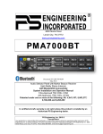
1
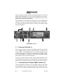
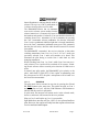
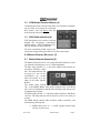
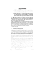
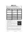
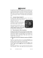
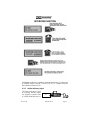
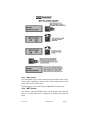
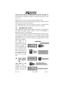
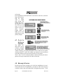
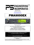
9800 Martel Road
Lenoir City, TN 37772
www.ps-engineering.com
PMA9000EX
Audio Selector Panel
Marker Beacon Receiver
High-fidelity Stereo Intercom System
with Bluetooth Phone interface & MP3 player
Pilot’s Guide
and
Operation Manual
202-920-0100
Revision 5
October 2010
This product is intended for Experimental Aircraft only.
Covered under one or more of the following Patent No.
4,941,187, 5,903,227, 6,160,496, 6,493,450
OCT. 2010
202-920-0100
Page 1
This pilot guide provides detailed operating instructions for the PS
Engineering PMA9000EX, Audio Selector Panel/Intercom Systems.
Please read it carefully before using the equipment so that you can
take full advantage of its capabilities.
This publication covers the basic operating areas of the PMA9000EX
systems. They are: Com Transceiver Selection, Receive Audio Selector, Intercom, Marker Beacon Receiver, Music, Front Panel Utility
Jack and Telephone.
PMA9000EX Controls
1.1 Power and Fail-Safe (1)
Unit power is turned on and off by pushing the volume knob. In the
OFF or "EMG" fail-safe position, the pilot headset is connected directly to Com 1 (will be heard in one ear, with stereo headset) as well
as unswitched input #1. This allows communication capability regardless of unit condition. Any time power is removed or turned OFF, the
audio selector will revert to fail-safe mode.
The power switch controls all audio selector panel functions, intercom and marker beacon receiver. All pushbutton selections and menu
modes will be remembered and return to the last state when turned on.
1.1
Communications Transmit (XMT) Selection (2)
The two buttons C1 and C2, (# 2) in the XMT section control which
communications radio is selected for transmitting. Push the lower button to select the desired COM transmitter. A green LED above the
Page 2
PMA9000EX Pilot Guide
Revision 5
button illuminates to indicate that the audio is
selected. The top row of RCV pushbuttons (#
3) allows selection of the receiver audio.
The PMA9000EX-Series has an automatic
com receiver selector system. Audio from the
selected transceiver is automatically heard in
the headsets and speaker (if selected). You can check this function by
switching from COM 1 transmitter to Com 2 transmitter by pressing
the COM 2 transmitter selector pushbutton. See that the associated
Com 2 receive pushbutton indicator light that is located immediately
above the Com 2 transmitter pushbutton turns green. This guarantees
that the pilot will always hear the audio from the transceiver selected
for transmit.
The PMA9000EX “remembers” the receiver selection, so that when
switching transmitters from COM 1 to COM 2, if COM 2 audio was
previously selected, COM 1 audio will continue to be heard. This
eliminates the pilot having to switch Com 1 audio back on, after
changing transmitters.
When switching from COM 1 to COM 2 while Com 2 was not previously selected, COM 1 audio will be switched off. In essence, switching the mic selector will not override prior selection of COM receiver
audio.
In normal (not split) modes, the PMA9000EX gives priority to the
pilot’s radio Push-To-Talk (PTT). If the copilot it transmitting, and
the pilot presses his PTT, the pilot’s microphone will be heard over
the selected com transmitter.
1.1.1.1
Split Mode
The split mode can be activated at any time by pressing the C1 and
C2 XMT buttons at the same time. This places the pilot on COM 1
and the Copilot on COM 2. All four COM indicators will illuminate to
indicate that the panel is in split mode.
In split mode, the intercom will remain active in the selected mode,
however, and music will be muted in the crew positions.
Pilot on COM 2 and Copilot on COM 1 is not possible.
Split Mode does not turn off Nav, ADF, or Aux selected audio to
pilot. However, the copilot will only hear the copilot-selected com
receiver and unswitched inputs
OCT. 2010
202-920-0100
Page 3
NOTE
Due to the nature of VHF communications signals, and the size
constraints in general aviation aircraft, it is probable that there will be
some bleed-over in the Split mode, particularly on adjacent
frequencies. PS Engineering makes no warranty about the suitability
of Split Mode in all aircraft conditions.
1.1.1.2
Swap Mode (Switch from Com 1 to Com 2 remotely)
With a yoke mounted, normally open momentary switch, the pilot can
change from the current Com transceiver to the other by depressing
this switch. To cancel "Swap Mode," the pilot may either press the
yoke mounted switch again, or select a different Com with the XMT
buttons.
1.1.1.3
Internal Recorder
The PMA9000EX comes equipped with an internal recorder. This digital system stores the last
incoming audio from the radio you have selected
for transmit. It can store up to 60 seconds of audio. The pilot and copilot hear the playback.
Because of the continuous nature of AWOS recordings, these will not trigger the recorder circuits.
1.1.1.3.1
Playback
Recording is automatic. To play back the message, press and hold the
XMT button for the communications radio that is selected for transmit for about 1 second or until the message plays back.
To stop the playback, hold the same button until the playback stops,
about 2 seconds. Then the next 1-second press will play the next earlier message stored.
The playback will stop automatically when the selected com audio
becomes active again. Press the button again to start the message
again. The audio received during playback is NOT stored.
Page 4
PMA9000EX Pilot Guide
Revision 5
1.2
COM Audio Receive Selector (3)
Communication audio from the other radio, not selected for transmit,
can be heard by pressing the associated
RCV button. You will always hear the
audio from the selected transceiver.
1.3
NAV Audio selection (4)
VHF Navigation receiver audio is selected
through two momentary, push-button,
backlit switches. VHF Navigation aid audio push buttons are labeled N1, N2.
The users can identify which receivers are
selected by noting which green LEDs are lit above the button.
2.0 Marker Beacon Receiver (5)
2.1
Marker Beacon Operation (5)
The Marker Beacon Receiver uses visual and audio indicators to alert
you when the aircraft passes over a 75 MHz transmitter.
The Blue lamp, labeled “O”, is the Outer Marker lamp and has an
associated 400-Hertz 'dash'
tone. The lamp and tone will
be keyed at a rate of two
tones/flashes per second
when the aircraft is in the
range of the Outer Marker
Beacon.
The Amber lamp, labeled
“M”, is the Middle Marker lamp and is coupled with a 1300 Hertz
tone. It is keyed alternately with short 'dot' and long 'dash' bursts at 95
combinations per minute.
The White lamp, labeled “I”, is the Inner marker and has a 3000 Hertz
'dot' tone. The lamp and tone will be keyed at a rate of six times per
second.
The MKR button controls audio selection, marker sensitivity, and
audio muting, and lamp test.
• MKR button press of < 1 second: toggles between high
and low receiver sense
OCT. 2010
202-920-0100
Page 5
•
MKR button press between 1 and 2 seconds: Activates
audio mute, and marker lamp test activated. The next beacon received will re-activate the audio.
•
MKR button press > 2 seconds: toggle marker audio on/
off. When the audio is selected, MKR will appear in the
display. Marker audio can also be controlled using the
same manner as Secondary Navaid Selection
Use "HI" sensitivity initially. This allows you to hear the outer
marker beacon about a mile out. Then touch the smaller MKR button
to switch into Low Sensitivity mode. “LO” sensitivity gives you a
more accurate location of the Outer Marker.
Holding the MKR button for two seconds activates marker test lamp,
which illuminates all three lamps simultaneously to assure the lamps
(internal and external) are in working order. Releasing the button returns to the last sensitivity. The marker audio level is preset at the
factory, and a service adjustment is available if necessary.
3.0 Intercom (6)
3.1
IntelliVox® VOX-Squelch
No adjustment of the IntelliVox® squelch control is necessary. There
is no field adjustment. Through three individual signal processors, the
ambient noise appearing in all six microphones is constantly being
sampled. Non-voice signals are blocked. When someone speaks, only
their microphone circuit opens, placing their voice on the intercom.
The system is designed to block continuous tones, therefore people
humming or whistling in monotone may be blocked after a few moments.
For consistent performance, any headset microphone must be placed
within ¼-inch of your lips, preferably against them. (ref: RTCA/DO214, 1.3.1.1 (a)). It is important to have the microphone element parallel to your mouth, and not twisted inside the cover.
It is also a good idea to keep the microphone out of a direct wind
path. Moving your head through a vent air stream may cause the IntelliVox® to open momentarily. This is normal.
The IntelliVox® is designed to work with normal aircraft cabin noise
levels (70 dB and above). Therefore, it may not always recognize
speech and clip syllables in a quiet cabin, such as in the hangar, or
without the engine running. This is also normal.
Page 6
PMA9000EX Pilot Guide
Revision 5
Oregon Aero MicMuff Part Numbers
Note: For optimum microphone performance, we recommend use of a
Microphone Muff Kit from Oregon Aero (1-800-888-6910). This will not only
optimize VOX performance, but will improve the overall clarity of all your
communications.
Headset
Manufacturer
Model
Part Number
Bose
Dynamic
Electret
M87
90010
90015
90020
David Clark
H10-30
H10-20, H10-40
H10-13.4, 13X
H20-10X
90010
90015
90015
90015
Lightspeed
All
90015
Peltor
7003
ANR Pro, 7000
90010
90015
Pilot
11-20, 11-90, 1776, DXL
90015
Sennheiser
All
90015
Telex
Airman 750, AIR4000
AIR3000, Echelon 100
90010
90015
3.2
Intercom Modes
The “ICS” pushbutton switch on the left side of
the PMA9000EX provides the selection of the
three intercom modes.
This button cycles through the intercom modes,
from left to right and then back, ISO, ALL, CRW
(Crew), ALL, and ISO. The illuminated text
shows the active mode .
ISO: The pilot is isolated from the intercom and is
connected only to the aircraft radio system. He will hear the aircraft
radio reception (and sidetone during radio transmissions). The copilot
and passengers will hear the music sources as configured by the audio
panel.
ALL: All parties will hear the aircraft radio and intercom. Crew will
hear Entertainment 1, passengers can hear Entertainment 1 or 2. During any radio or intercom communications, the music volume automatically decreases. The music volume increases gradually back to
OCT. 2010
202-920-0100
Page 7
the original level after communications have been completed. An
Alternate Intercom Function is available that prevents the passengers
from hearing aircraft radios in ALL mode. See Section 4.2 for details.
CREW: Pilot and copilot are connected on one intercom channel and
have exclusive access to the aircraft radios. Again, the music that the
crew and passengers will hear is controlled in the music distribution
setup.
3.3
Intercom Volume Control (7)
The small volume control knob adjusts the loudness of the intercom
for the pilot and copilot. It has no effect on
selected radio levels, music input levels or
passengers' volume level.
The larger, outer volume control knob controls intercom volume for the passengers. It
has no effect on radio or music levels.
Adjust the radios and intercom volume for a
comfortable listening level. Most general
aviation headsets today have built-in volume
controls; therefore, volume also can be further adjusted at the individual headset.
3.3.1 Mono Headsets in Stereo Installation
The pilot and copilot positions work with stereo or mono headsets.
All passenger headsets are connected in parallel. Therefore, if a monaural headset is plugged in to a PMA9000EX Stereo installation, one
channel will be shorted. Although no damage to the unit will occur,
all passengers will lose one channel, unless they switch to the
“MONO” mode on the headset.
4.0 EnCoder And Push Switch interface (ECAPS)
(8)
ECAPS is a system that consists of two encoding data knobs and a
push-push switched integral into the small data knob. These control
the menu, submenus, and selection of items for control.
The primary menu contains frequently accessed items: SPR (cockpit
Speaker), TEL (telephone) MKR (Marker audio), and MUTE (music
mute control).
Pressing the small knob for two (2) seconds will activate the sub
menus. Submenus contain: ADF, DME and AUX audio, MP3 and
Page 8
PMA9000EX Pilot Guide
Revision 5
other music selections and controls, Alternate Intercom mode control,
Public Address, and LCD display controls.
Turn the large data knob to view the sub menus. Turn the small knob
to toggle selections on or off, or adjust levels.
OCT. 2010
202-920-0100
Page 9
Pushing the small data knob will activate the option, and exit the
menu, or, the option will be selected automatically after five (5) seconds.
The menu function will always come up on the display with last used
function first.
4.1
Cockpit Speaker
The speaker (SPR) can be turned on or off in the same manner as the
MKR from the primary menu. This control will place all selected audio on the cockpit speaker when this switch is selected. Except for the
unswitched audio, the speaker amplifier is not active in the "Split
Mode”.
Unswitched audio, (the inputs dedicated to autopilot disconnect, altimeter warning, etc.) will come through the speaker regardless of the
speaker button position.
Depending on installation, important audio annunciations such as radar altimeter or autopilot disconnect will come over the speaker even
if it is not selected, while other unswitched, but muted inputs, such as
GPS alerts, will only be present if the SPR button is selected. Consult
your professional avionics installer for these important configuration
details.
4.2
Standard/Alternate Intercom Function
Alternate Intercom Function is a mode that allows everybody to talk
on the intercom, but the passengers do NOT hear the aircraft radios.
In addition, when the aircraft radios are active, the crew does not hear
the passengers’ microphones, although passengers continue to hear
each other. This function is selected through the ECAPS system.
4.3
Utility Jack (9)
The 2.5-millimeter (3/32”) jack on the front of the PMA9000EX has
three distinct functions:
• Music input
• Advisory audio input
• Wired Cell phone input
4.3.1 Front Jack Music Input
When used as a music input, the front panel jack is treated as Music
#1. However, thanks to the PMA9000EX controls, it can be
Page 10
PMA9000EX Pilot Guide
Revision 5
distributed to all users, regardless of the intercom mode. A patch cord
is available with 2.5 mm to 3.5 mm (3/32" to 1/8" ) adapter cord (PS
Part Number 425-006-2535).
4.3.2 Audio Advisory Input
The front jack can be used
as a priority advisory input
for auxiliary systems such
as a GPS terrain advisory or
OCT. 2010
Crew
202-920-0100
Page 11
portable traffic watch system. To prevent radio or intercom from muting this input, turn off the “Mute” function.
4.2.2.1
Smart Jack Function
When the PMA9000EX has a signal on music #1 input coming in
from the rear connector, the front panel jack automatically becomes a
Priority Advisory input, and is heard in the crew headphones.
NOTE
The front jack is no substitute for the certified installation of alerts
such as the GPS waypoint or autopilot tones. These still must be hard
wired into the back by your installer.
4.3.3 Cellular phone
When a wired cellular telephone is connected to this jack using available 2.5 mm to 2.5 mm adapter cord (PS Part Number 425-006-7026),
the PMA9000EX audio panel will connect the intercom to the cell
phone when the “TELEPHONE mode is activated, and behave as described in section 4.3.2. The telephone ringer, if present, will be
heard unless the input is muted by other radio or intercom., however,
with the wired connection, the TELEPHONE RINGING message will
not be displayed.
4.3
Telephone (TEL) Mode
The TEL mode serves as a full duplex interface and distribution for
compatible portable cellular phones with hands free jacks or Bluetooth capable.
4.3.1 Bluetooth
Before the PMA9000EX can be used in TEL mode with a Bluetooth
connection, the unit must be paired with a specific phone. Activate
the “seek device” function on the cell phone, and then enter the access
code “0000” when the phone detects the “PMA9000EX” on the list of
available devices.
If the PMA9000EX doesn’t pair with the Bluetooth phone,
(“Unsupported device” message, for example), verify that the audio
panel is in the Hands free mode. Turn the audio panel off, and then
back on, while holding the Nav 1 button, until “Hands Free Mode” is
displayed. If Headset Mode is displayed, repeat the process of holding
Nav 1 button while the audio panel is powered up, until Hands Free
is displayed. Units are delivered in Hands free mode.
Page 12
PMA9000EX Pilot Guide
Revision 5
This process will be necessary for any phone to be used, and only one
cell phone can be pared with the audio panel at a time. If the additional phones are paired with the PMA9000EX, only the first phone
will transfer audio to the panel.
4.3.1.2
Using Bluetooth
When using Bluetooth, the PMA9000EX will display “TELEPHONE
RINGING” and play a ring tone. Pressing the encoder knob will connect the call. The PMA9000EX exits the telephone mode automatically when the cellular phone hangs up.
To make an outgoing call, select TEL using the ECAPS system. Using the cell phone, dial the desired number and select “send” on the
cell phone. You now connected to the telephone. NOTE: You will
continue to hear the selected Com. When you press the PTT, the cell
phone will mute.
Note to iPhone users: When dialing out from the phone, or when an
incoming call is answered from the phone, it may be necessary to
manually select the “PMA9000EX” as an audio source on the main
phone screen of the iPhone.
4.3.2
Telephone Distribution
The TEL mode connects the telephone to the users as follows: In
ALL mode, all crew and passengers will be heard on the phone. Com
and selected radio audio is also heard in the headsets. If the pilot or
copilot pushes the radio PTT, their mic will be transferred to the selected Com radio. The telephone party will not hear ATC and vice
versa.
In CREW mode, only the pilot and copilot are connected to the telephone. Passengers will not hear the telephone. The pilot and copilot
will also have transmit capability on the selected transceiver.
In ISO mode, when the PMA9000EX is in the TEL mode, the pilot
position is in the "Phone Booth." Only the pilot will hear the telephone, and only he will be heard. He will also have access to Com 1
or 2, and will transmit on that radio using the PTT. All selected audio
is provided to the pilot.
NOTE: Because the cellphone uses an intercom circuit, all stations on
that circuit lose intercom capability when the cell phone is in use.
WARNING
FCC regulation 47 CFR 22.925 prohibits the use of 800 MHz Cellular
OCT. 2010
202-920-0100
Page 13
handsets in any aircraft that is airborne. Violation of this rule could
result in suspension of service and/or a fine.
4.4
Music Input & Distribution
There are three music sources available to the PMA9000EX: MP3,
Music 1, and Music 2. Music 1 input can be either on the front jack,
OR the Music 1 input at the rear connector. Music 2 is wired into the
rear connector only.
The PMA9000EX has two music channels, which can use any of
three sources. One music channel is provided to the crew, and can be
distributed to the passengers. Another music input is dedicated to the
Passengers stations. The three sources, Music 1, Music 2 and MP3
can be directed via the ECAPS to these channels.
Note: If you don’t hear the music device as expected, verify which
sources is selected for the crew.
Page 14
PMA9000EX Pilot Guide
Revision 5
If the MP3 player is selected for the crew, and music is playing in the
front panel jack or Music 1, BOTH sources will be heard, because the
front panel jack can also be used for alert audio and telephone.
Select MUSIC DISTRIBUTION submenu, push the knob, and select
the desired configuration from that menu.
4.4.1 Music Volume
Music #1 volume is controlled by the small data knob at all times,
unless the MP3 player is active, in which case the small data knob
controls MP3 Volume.
In addition, music input 1 and music input 2 have individual volume
controls that are accessible through the ECAPS system. Push the
OCT. 2010
202-920-0100
Page 15
small data knob for 2 seconds, and then turn the large data knob until
MUSIC 1 or MUSIC 2 is shown. Then turn the small data knob to
change the volume. The display will revert and store the values after 3
seconds.
4.4.2 Music Mute Control
PMA9000EX controls the music muting allowing the user to tailor the
SoftMute™ to their taste and situation. There are two SoftMute™ muting circuits. The SoftMute™ circuit will cut the music almost completely out whenever there is conversation on the radio or intercom.
When that conversation stops, the music returns to the previous level
comfortably, over a second or so.
For those occasions when the music muting isn’t necessary or desired,
the SoftMute can be disabled from the front panel.
Push the small knob to highlight the cursor. Select the MUTE by
turning the small knob, and push the knob again to toggle mute
on or off. This mute control is for the Crew music only. Passenger
music muting is controlled through a switch installed in a location
convenient to the passengers.
Page 16
PMA9000EX Pilot Guide
Revision 5
4.4.3 MP3 On/Off
The internal MP3 player can be turned on and off and the order of play
can be either sequential or random. Each of these functions has a submenu item in the ECAPS system.
The MP3 player resets to off when the PMA9000EX is turned off.
4.4.4 MP3 Volume
The volume of the internal MP3 player can be adjusted at any time the
player is on and main menu is displayed, by turning the small data
knob.
OCT. 2010
202-920-0100
Page 17
4.4.5 MP3 Music Track selection
The track can be changed whenever the MP3 player is operating by
turning the large data knob. The track title is displayed momentarily.
The display also changes to show the title when the track changes.
4.4.6 MP3 Random Mode
The PMA9000EX MP3 player can be set to play the files in sequence,
or in a random order. The MP3 Random Mode is on the submenu.
Page 18
PMA9000EX Pilot Guide
Revision 5
4.4.7 MP3 File Transfer
The PMA9000EX has 1 GB of internal storage (512 MB before S/N
B01094). The program inside the unit will recognize and import any
compatible audio files (.wav, .mp3, unprotected .wma) from an external
source, through the USB cable. The PMA9000EX is not compatible
with iTunes formats.
4.4.7.1
Laptop transfer
Due to the transfer rate advantages, we recommend that you transfer
files from a laptop to the PMA9000EX if possible. Direct USB device
transfer requires 35-40 minutes to transfer 1G of songs, Laptops typically require 4-6 minutes for the same amount of data with USB 2 port.
PS Engineering recommends Microsoft XP operating system or later.
1. Using the supplied 2.5 mm-to-USB cable, along with the supplied
USB-to-USB adapter cord (PS Part number 425-003-1454), connect
this set of cables from the PMA9000EX front panel jack to a PC
USB port.
2. With the PMA9000EX turned off, push and hold the small data
knob while powering the PMA9000EX on. Wait until the audio
panel displays "USB drive mode" before releasing.
3. When windows recognizes the PMA9000EX as a removable drive,
select “Open folder to view files using Windows Explorer”
4. Create a subfolder (name it whatever you wish, like “PlaneMusic”)
on your PMA9000EX to contain the specific music files you will
want on the airplane.
5. Copy the desired music into this folder.
6. After transfer is complete, turn the audio panel off, and back on to
return to normal operation.
4.4.7.2
Direct USB Device Transfer
For best results, the following procedure should be used for a USB device when used with the PMA9000EX. The USB drive should be reformatted before being used with the PMA9000EX and only music files
should be stored, in a single subfolder on the USB Device.
1. Connect the USB Drive to your PC
2. From “Start” select “My Computer” and select the external drive.
3. Right Click on the device, and select “Format. . . “
OCT. 2010
202-920-0100
Page 19
4. Select “FAT” as File system, and “Start” WARNING, this will
erase all files on this device.
5. After formatting is complete, right click in the drive, and select
“New. . . Folder” and create a new folder for your music that you
will put on your PMA9000EX
6. Transfer your music files into the new music folder.
We recommend having no more
than 1G of music files in this
folder. To upload from a USB
memory device, select the
“Music Transfer” function on the
submenu. Follow the onscreen
instructions; connect the memory
device to the 2.5mm to USB cable, and then plug the cable into
the front of the PMA9000EX
when prompted.
We recommend that you only
store 1G (512MB before Serial
Number B01094) or less of files
on the audio panel, to ensure that
all the desired songs are played
on the PMA9000EX. Because of
the Microsoft file protocol, we
cannot predict which files will be
omitted
Page 20
PMA9000EX Pilot Guide
Revision 5
After the music transfer is complete, the PMA9000EX will automatically reset to store the files and create the new play list. Therefore it is
not advisable to upload files in flight or when the audio panel is otherwise in use.
Note: For best results, use quality name-brand USB devices.
Different types of files, and music file programs may result in variation
in the volume level of the stored music.
The maximum transfer rate will decrease by about 1% each time the
unit is uploaded, therefore frequent music upload is not advised.
4.5
Backlighting & Contrast
The PMA9000EX has an automatic photocell dimming of the annunciation LEDs and marker lamps. Control of the text backlighting is
through the aircraft avionics dimmer.
The LCD display has backlighting controlled by the automatic photocell dimming. In addition, the text inverts for nighttime mode when the
ambient light is low. As the light decreases to a dim sunlight, the LCD
backlighting will turn on, and you may notice a brightening of the LCD
under some conditions.
The contrast on the
LCD display can be
controlled for individual
preference. Activate the
LCD CONTRAST submenu, and turn the outer
knob to adjust the level.
There are 10 steps, with
10 as the lowest contrast. NOTE: A contrast
level of 3 or 4 is optimal.
4.6
ADF/DME/
AUX Monitoring
ADF, DME and AUX
(auxiliary) audio is
available when selected
through the ECAPS
graphical and data conOCT. 2010
202-920-0100
Page 21
trol system.
Press and hold the small data knob to activate the sub menu, rotate the
large data knob to
find the AUX,
ADF or DME
page. Rotate the
small knob to toggle the audio on or
off. When on, the
letter A or D will
appear in the primary
display.
Unlike ADF or
DME, AUX is not
annunciated on the
primary display.
4.7
Public
Address
Function
The Public Address (PA) can be
activated through
the ECAPS Public
Address submenu. The pilot microphone will be heard on the speaker
when the pilot PTT is used. The copilot can continue to use the selected
com radio while the pilot will now be heard over the speaker.
The C1 and C2 receive indicators blink to indicate that the pilot microphone is no longer connected to the radio or intercom.
4.8
Warranty & Service
In order for the factory warranty to be valid, the installations in a certified aircraft must be accomplished by an FAA-(or other ICAO agency)
certified avionics shop and authorized PS Engineering dealer. If the
Page 22
PMA9000EX Pilot Guide
Revision 5
unit is being installed by a non-certified individual in an experimental
aircraft, a factory-made intercom harness must be used for the warranty
to be valid.
PS Engineering, Inc. warrants this product to be free from defect in material and workmanship for a period of two (2) years from the date of
purchase from an authorized PS Engineering dealer. During the first
twelve (12) months of the three-year warranty period, PS Engineering,
Inc., at its option, will send a replacement unit at our expense if the unit
should be determined to be defective after consultation with a factory
technician. For the remaining twelve (12) months of the two-year warranty period, the shipping costs for the exchange unit will be borne by
the customer.
All transportation charges for returning the defective units are the responsibility of the purchaser. All domestic transportation charges for returning the exchange or repaired unit to the purchaser will be borne by PS Engineering, Inc.
The risk of loss or damage to the product is borne by the party making the
shipment, unless the purchaser requests a specific method of shipment. In this
case, the purchaser assumes the risk of loss.
This warranty is not transferable. Any implied warranties expire at the expiration date of this warranty. PS Engineering SHALL NOT BE LIABLE FOR
INCIDENTAL OR CONSEQUENTIAL DAMAGES. This warranty does not
cover a defect that has resulted from improper handling, storage or preservation, or unreasonable use or maintenance as determined by us. This warranty is
void if there is any attempt to dissemble this product without factory authorization. This warranty gives you specific legal rights, and you may also have other
rights, which may vary from state to state. Some states do not allow the exclusion of limitation of incidental or consequential damages, so the above limitation or exclusions may not apply to you.
All items repaired or replaced under this warranty are warranted for the remainder of the original warranty period. PS Engineering, Inc. reserves the
rights to make modifications or improvements to the product without obligation to perform like modifications or improvements to previously manufactured products.
4.9
Factory Service
The units are covered by a two-year limited warranty. See warranty information. Call PS Engineering, Inc. at (865) 988-9800 before you return any unit. After discussing the problem with the technician and you
obtain a Return Authorization Number, ship product to:
PS Engineering, Inc.
Attn: Service Department
OCT. 2010
202-920-0100
Page 23
9800 Martel Rd
Lenoir City, TN 37772
(865) 988-9800 FAX (865) 988-6619
Email: [email protected]
Units that arrive without an authorization number, or telephone
number for a responsible contact, will be returned un-repaired. PS
Engineering is not responsible for loss of items in transit.
Index
ADF/DME/AUX.................22
Intercom Mode, Alternate
..................................... 10
Public Address............. 23
Audio Advisory Input .......11
Intercom Squelch ........... 6
Split Mode...................... 3
Audio Selector Panel..........2
Internal recorder............. 4
Telephone.................... 12
Cockpit Speaker ..............10
Laptop Connection....... 19
Telephone, Bluetooth .. 12
Data Knob ..........................8
Marker Beacon............... 5
Telephone, Cellular ..... 12
Backlight & Contrast ........21
MP3.............................. 17
Transmitter Select ......... 2
ECAPS ...............................8
Music Distribution......... 14
Volume, Intercom .......... 8
File Transfer .....................19
Music Mute................... 16
Volume, Music ............. 15
Front Panel Utility Jack ....10
NAV Selection................ 5
Warranty ...................... 23
Intercom .............................6
Power............................. 2
PS Engineering, Inc. 2008 ©
Copyright Notice
Copyrighted information in this manual is subject to change without notice. PS Engineering reserves the right to
improve or change the products or contents of this manual, without notification of any person or agency. The
contents of this pilot’s guide may be downloaded, stored and reprinted for personal use provided that this
copyright information is included. Commercial use is strictly prohibited. For further information contact the
Publications Manager at PS Engineering, Inc., 9800 Martel Road, Lenoir City, TN 37772. Phone (865) 9889800
Page 24
PMA9000EX Pilot Guide
Revision 5