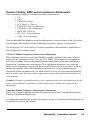
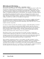
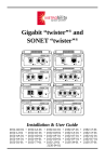
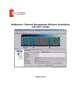
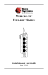
1
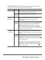
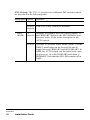
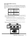
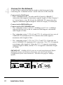
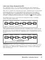
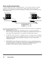
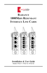
“redundant twister”™
“redundant twister”“
TX
RX
TX
TM
2731
RX
AT
AT
AT
SW
LK
100BASE-TX/FX
LK
LK
A
RESET
B
SECONDARY
PRIMARY
MAIN
PWR
“redundant twister”“
TX
RX
TX
TM
2731
RX
AT
AT
AT
SW
LK
100BASE-TX/FX
LK
LK
A
RESET
B
SM (LH)
SECONDARY
SM (LH)
PRIMARY
MAIN
PWR
“redundant twister”“
TX
RX
TX
TM
2731
RX
AT
AT
AT
SW
LK
100BASE-TX/FX
LK
LK
A
RESET
B
SM (ELH)
SECONDARY
SM (ELH)
PRIMARY
MAIN
PWR
“redundant twister”“
AT
TX
RX
AT
TX
RX
TM
2731
AT
A
RESET
B
SW
LK
100BASE-TX/FX
LK
LK
PRIMARY
SECONDARY
MAIN
PWR
“redundant twister”“
AT
AT
AT
LK
LK
TM
2731
A
RESET
B
SW
LK
SECONDARY
100BASE-TX
PRIMARY
MAIN
PWR
“redundant twister”“ 2711
TM
AT
RESET
X
X
II
SW
10BASE-T
AT
LK
SECONDARY
AT
X
II
LK
PRIMARY
A
B
II
LK
MAIN
PWR
Installation & User Guide
100Mbps Models: 2731-11/ 2731-13/ 2731-14/ 2731-15/ 2731-17/ 2731-1J
10Mbps Model: 2711-11
Metrobility “redundant twister”™
Standalone Units
10Mbps
2711-11 ______
100Mbps
2731-11 ______
2731-13 ______
2731-14 ______
2731-15 ______
2731-17 ______
2731-1J ______
RJ-45 to redundant RJ-45
RJ-45 to redundant RJ-45
RJ-45 to redundant FX multimode SC
RJ-45 to redundant FX singlemode SC
RJ-45 to redundant FX multimode ST
RJ-45 to redundant FX singlemode SC (40km)
RJ-45 to redundant FX singlemode SC (100km)
Lancast® Intelligent “redundant twister” Modules
10Mbps
7711-11-75 ___ RJ-45 to redundant RJ-45
7712-11-75 ___ RJ-45 to redundant RJ-45 with SONAR
100Mbps
7731-11-75 ___ RJ-45 to redundant RJ-45
7731-13-75 ___ RJ-45 to redundant FX multimode SC
7731-14-75 ___ RJ-45 to redundant FX singlemode SC
7731-15-75 ___ RJ-45 to redundant FX multimode ST
7731-16-75 ___ RJ-45 to redundant FX singlemode ST
7731-17-75 ___ RJ-45 to redundant FX singlemode SC (40km)
7731-1J-75 ___ RJ-45 to redundant FX singlemode SC (100km)
7732-11-75 ___ RJ-45 to redundant RJ-45 with SONAR
This publication is protected by the copyright laws of the United States and other countries, with all rights
reserved. No part of this publication may be reproduced, stored in a retrieval system, translated, transcribed,
or transmitted, in any form, or by any means manual, electric, electronic, electromagnetic, mechanical,
chemical, optical or otherwise, without prior explicit written permission of Metrobility Optical Systems, Inc.
© 2002 Metrobility Optical Systems, Inc.
All rights reserved.
Printed in USA.
Table of Contents
“redundant twister” Installation & User Guide
Overview ..................................................................................................................... 5
Installation Guide ....................................................................................................... 7
STEP 1: Unpack the “redundant twister” .................................................... 7
STEP 2: Choose an Appropriate Location .................................................. 7
STEP 3: Set the DIP Switches ..................................................................... 8
Set the MDI-II/MDI-X Switches ................................................. 11
STEP 4: Connect to the Network .............................................................. 12
STEP 5: Apply Power to the “redundant twister” ..................................... 14
User Guide ................................................................................................................ 17
LED Operation .......................................................................................... 17
Reset Push Button ..................................................................................... 18
Link Loss Carry Forward (LLCF) ............................................................. 19
Back-to-Back Application ......................................................................... 20
Topology Solutions ................................................................................... 21
Technical Specifications ............................................................................ 22
Straight/Crossover RJ-45 Twisted-Pair Cables ......................................... 24
Product Safety, EMC and Compliance Statements ................................... 25
Warranty and Servicing ............................................................................. 26
Lancast is a registered trademark; Metrobility Optical Systems, the Metrobility Optical Systems logo, “twister”
and “redundant twister” are trademarks of Metrobility Optical Systems, Inc. All others are trademarks of their
respective owners.
“redundant twister” technology is a patent of Metrobility Optical Systems, Inc.
The information contained in this document is assumed to be correct and current. The manufacturer is not
responsible for errors or omissions and reserves the right to change specifications at any time without notice.
4
Overview
The Metrobility “redundant twister” offers the resiliency of data link
redundancy to ensure network integrity with no down time. This link duplication
provides the nonstop networking capability essential for high priority traffic and
mission-critical applications. The “redundant twister” is a 100BASE-TX to TX/FX
or 10BASE-T to 10BASE-T device that provides full redundant data paths. In
Dynamic Recovery Mode (DRM), the “redundant twister” actively monitors the
primary link and if it fails, automatically activates the secondary link without
interruption to network operation.
The “redundant twister” has the following features:
• Immediately switches over from the primary to the secondary link if the
primary link fails.
• Supports full- and half-duplex operation.
• Provides redundant power to ensure no down time.
• Can be configured to operate in Dynamic Recovery Mode (DRM) to ensure
session integrity and increased uptime. (2711-11 only)
• Can be configured to operate in Network Select Mode (NSM) to redirect and
isolate traffic adding extra security. (2711-11 only)
• Fast Ethernet models demonstrate a maximum loss of 2-3 packets (measured
with minimum packet size and minimum inter-packet gap) due to fail-over
transition.
• Can be configured to return automatically to the primary link after the failure
condition is resolved.
• Provides minimal impact on the round trip delay for communication in halfduplex collision domains.
• Link Loss Carry Forward* enable/disable functionality. (2711-11 only)
• Can be configured to operate with auto-negotiating devices.
• The twisted-pair ports on the 2711 are equipped with an MDI-II to MDI-X
switch eliminating the need for crossover cables.
* Refer to the page titled “Link Loss Carry Forward (LLCF)” in the User Guide section of this document for
more detailed information.
Metrobility “redundant twister”
5
The “redundant twister” is available in several different models. These models each
contain a MAIN port, a PRIMARY port and a SECONDARY port. Redundancy is
provided between the PRIMARY and SECONDARY ports. The models are as
follows:
Model
Number
Mbps
Connectors
Maximum Supported
Link Length
2711-11
2731-11
2731-13
2731-14
2731-15
2731-17
2731-1J
10
100
100
100
100
100
100
RJ-45 to Redundant RJ-45
RJ-45 to Redundant RJ-45
RJ-45 to Redundant FX multimode SC
RJ-45 to Redundant FX singlemode SC
RJ-45 to Redundant FX multimode ST
RJ-45 to Redundant FX singlemode SC
RJ-45 to Redundant FX singlemode SC
100m/100m
100m/100m
100m/2km
100m/15km
100m/2km
100m/40km
100m/100km
6
Installation Guide
Installation Guide
Follow the simple steps outlined in this section of the guide to install and start
using your Metrobility “redundant twister”.
1
Unpack the “redundant twister”
Check that the following components have been included:
• “redundant twister” 2711 or 2731
• Two (2) 12V Power Supplies
• Four (4) Rubber Feet
Your order has been provided with the safest possible packaging, but
shipping damage does occasionally occur. Inspect your order carefully for
damage that may have occurred during shipment. If you discover any
shipping damage, notify the carrier and follow their instructions for
damage and claims. Be sure to save the original shipping carton if return or
storage of the unit is necessary.
2
Choose an Appropriate Location
The “redundant twister” is intended for use in either office or industrial
environments. The converter must be located within six (6) feet of the AC
power source being used and placed as far away as possible from electrical
noise generating equipment such as copiers, electrostatic printers and other
motorized equipment. If exposed twisted-pair wiring is used nearby, the
wiring should be routed as far away as possible from power cords and data
cables to minimize interference.
The units may be oriented in any manner which permits the user to make
physical connection to the power supplies and leaves a minimum of six (6)
inches of space for proper ventilation.
TUV Compliance Note: For pluggable equipment, the socket outlet must be
installed near the equipment and be easily accessible.
Bei Geräten mit Steckanschluß muß die Steckdose nahe dem Gerät
angebracht und leicht zugänglich sein.
Metrobility “redundant twister”
7
A set of DIP switches, located on the back panel, provides user-selectable
configurability options for several modes of operation. Refer to the table
on the following pages for the proper setting of the DIP switches.
BO
AU TH
TO
LIN RE
V
K
BO ER
TH T
3
Set the DIP Switches
TX
TM
A
B
O
N
1 2 3 4
POWER
DC INPUT/12VDC
R
EV
BO ER
TH T
K
LI
N
BO
AU
TX
O
N
1 2 3 4
TX
BO
AU TH
TO
LIN RE
K V
LL BOT
CF H
RE
D
M
OD
E
UP
DOWN
TO
TH
“redundant twister” 2731
A
B
1 2 3 4 5 6
ON
OFF
POWER
DC INPUT/12VDC
TX
BO
AU TH
TO
LI RE
NK V
LL BOT
CF H
RE
D
M
OD
E
“redundant twister” 2711
UP
DOWN
8
Installation Guide
1 2 3 4 5 6
ON
OFF
2731-XX and 2711-11: The DIP switches are marked on the back panel
and can be set for the following operational functions.
Switch Name
Position
TX BOTH
UP
Operation
Transmits data on both the PRIMARY and
SECONDARY ports simultaneously.
DOWN Transmits data on the active port only.
(default)
AUTO
REVERT
UP
Active port automatically reverts back to the
PRIMARY port when the primary link is
reestablished.
DOWN Active port will not revert back to the PRIMARY
(default) port when a primary link is reestablished. The
SECONDARY port remains active. Use the
RESET push button located on the front of the
unit to force the active port back to the PRIMARY
port and clear the SW LED.
LINK
BOTH
UP
Link signals are sent out on both the PRIMARY
and SECONDARY ports (i.e. Link is sent out both
ports).
DOWN Link signals are sent out on the active port only.
(default) With the LINK switch in this position, data is not
transmitted out the inactive port regardless of the
TX switch setting.
IMPORTANT NOTE: With the LINK switch in
this position, the device on the other end of the
PRIMARY and SECONDARY ports must not be
in auto-sense mode.
Metrobility “redundant twister”
9
2711-11 Only: The 2711-11 provides two additional DIP switches which
are described in the following table.
Switch Name Position
*
LLCF
UP
Operation
Link Loss Carry Forward is enabled.
DOWN Link Loss Carry Forward is disabled.
(default)
RED
MODE
UP
Operates in Dynamic Recovery Mode (DRM). If
(default) the PRIMARY link fails, the SECONDARY port
becomes active. Refer to the description of the
AUTO switch.
DOWN
Operates in Network Select Mode (NSM). Use the
RESET push button on the front of the unit to
toggle between PRIMARY and SECONDARY. In
NSM, the AUTO switch sets the initial active port
on power up. Up is SECONDARY and down is
PRIMARY. Note that the SW LED remains off in
NSM.
*
Refer to the page titled “Link Loss Carry Forward (LLCF)” in the User Guide section of this manual for more
information.
10
Installation Guide
Set the MDI-II/MDI-X Switches
(2711-11 only)
Next to each RJ-45 connector is a small push button switch used to implement the transmit and receive crossover functionality for that particular port.
The position of this switch connects the transmit and receive signal pairs in
either a straight through or crossover configuration. The signal routing is as
follows:
Switch Position
Connection
TX+ to TX+
TX- to TXRX+ to RX+
RX- to RXTX+ to RX+
TX- to RXRX+ to TX+
RX- to TX-
When setting the MDI-II/MDI-X switch, simply press the push button IN
or OUT to achieve the desired setting. Observe the positioning of the push
button in relation to these symbols:
• The parallel symbol (II) indicates a straight through or parallel
connection. Press the button OUT for a straight through connection.
• The cross symbol (X) indicates a crossover connection. Press the
button IN for a crossover connection.
These two symbols are clearly marked on the front panel in conjunction
with each switch. Refer to the illustration below:
“redundant twister”
AT
RESET
X
X
II
SW
10BASE-T
AT
X
II
LK
SECONDARY
TM
LK
2711
AT
A
B
II
PRIMARY
LK
MAIN
PWR
AT
X
II
LK
PRIMARY
Metrobility “redundant twister”
11
4
Connect to the Network
A total of three connections must be made on the front panel when
connecting the “redundant twister” media converter to the network.
Connect to the MAIN port.
• Each “redundant twister” provides one RJ-45 jack for 10BASE-T
connections that supports a maximum segment length of 100m Category 3
or 5 twisted-pair; or one RJ-45 jack for 100BASE-TX connections that
support a maximum segment length of 100m of Category 5 twisted-pair.
Connect to the PRIMARY port.
Connect to the SECONDARY port.
• The “redundant twister” 2731-11 (100Mbps) and 2711-11 (10Mbps)
each provide two sets of RJ-45 connectors that support a maximum
cable length of 100m.
• The “redundant twister” 2731-13 and 2731-15 each provide two sets of
100BASE-FX multimode SC/ST connectors that each support a
maximum cable length of 2km.
• The “redundant twister” 2731-14, 2731-17 and 2731-1J provide two
sets of 100BASE-FX singlemode SC connectors. The 2731-14 supports
a maximum cable length of 15km, the 2731-17 supports a maximum
segment length of 40km, and the 2731-1J supports a maximum length
of 100km.
IMPORTANT: 100Mbps RJ-45 ports are wired straight through. Before
making the proper twisted-pair connection, you must verify the port
configuration of the connected device. This does not apply to 10Mbps
models.
External Crossover Function
Device with Straight Through “redundant twister” 2731
TP Port Configuration
TP Port Configuration
1
2
3
6
12
TD+
TDRD+
RD-
Installation Guide
TD+
TDRD+
RD-
1
2
3
6
Embedded Crossover Function
“redundant twister” 2731
TP Port Configuration
1
2
3
6
MDI
TD+
TDRD+
RD-
Typical Hub
TP Port Configuration
MDI–X
TD+
TDRD+
RD-
1
2
3
6
2731-XX 100BASE-TX connections:
• When connecting a “redundant twister” 2731 to another device that is
internally wired straight through, use a crossover cable.
• When connecting a “redundant twister” 2731 to a device that is internally
wired crossed over, use a straight through cable.
• If you do not know the internal wiring configuration of the other device’s
RJ-45 port, consult the product documentation.
• Refer to the diagrams titled “Straight/Crossover RJ-45 Twisted-pair
Cables” in the User Guide section of this manual for more detailed
information.
When making fiber optic connections, be sure that the transmit (TX)
optical conductor of the “redundant twister” connects to the receive (RX)
optical conductor of the connected device; and be sure that the transmit
(TX) optical conductor of the device connects to the receive (RX) optical
conductor of the “redundant twister” for both the PRIMARY and SECONDARY links.
“redundant twister”
AT
TX
RX
AT
TX
RX
TM
TM
2731
AT
A
RESET
B
SW
LK
100BASE-TX/FX
LK
SECONDARY
LK
PRIMARY
MAIN
PWR
2711-11 10BASE-T connections:
Be sure to set the MDI-II/MDI-X switch appropriately for each port.
Once power is applied to the unit, use the Link (LK) LEDs on the front
panel to verify correct segment connectivity. The LK LED illuminates
provided there is an active device connected to the other end of the cable
sending idle link signals.
Metrobility “redundant twister”
13
5
Apply Power to the “redundant twister”
Power is provided to the “redundant twister” from the desktop, universal
input, switching power modules. Each universal power supply module
provides a DC jack for connection of the desktop switching power supply
module. The power modules are equipped with S760 hollow-type plugs
and standard IEC 320-type AC power receptacles.
IMPORTANT: When making power connections, connect the DC power
cord to the DC input jack located on the back panel before making the
connection to the outlet. Failure to do this properly can damage the
product and void the unit’s warranty.
If a redundant power supply module is being used, simply connect the
individual power cords to separate power sources.
A convenient bracket provides strain relief from the weight of the cords to
eliminate an accidental disconnection.
BO
TH
AU
TO
R
EV
LIN
E
K
BO RT
TH
The “redundant twister” does not have a power switch. After connecting
the unit to the AC receptacle, verify that the PWR (power) LEDs illuminate. A steady green light indicates the unit is receiving power. There is
one LED for each power supply. They are labeled A and B.
TX
TM
A
B
O
N
1 2 3 4
POWER
DC INPUT/12VDC
Rear Panel “redundant twister” 2731
14
Installation Guide
Upon receiving power, the “redundant twister” goes into normal operation
mode and automatically provides the appropriate signal conversion
between the connected network segments. Use the individual Link (LK)
LEDs on the front panel to verify correct segment connectivity.
Refer to the section titled “LED Operation” in the User Guide section of
this manual for more information.
If an additional extension cord is used to connect the power module to the
power source, the following guidelines must be followed:
While one end of the AC power cord can be fitted with whatever plug is
standard for the country of operation, the end that connects to the
“redundant twister” power supply module must have a female plug that
fits this type of AC receptacle.
• AC 115V (North American): use a UL-listed and CSA-certified cord
set consisting of a minimum 18 AWG, type SVT or SJT three
conductor cord, a maximum of 15 feet in length and a parallel blade,
grounding-type attachment plug rated 15A, 125V.
• AC 230V (USA): use a UL-listed cord set consisting of a minimum
No. 18 AWG, type SVT three-conductor cord, a maximum of 15 feet
in length and a Tandem blade grounding-type attachment plug rated
15A, 250V.
• 240V (outside USA): use a cord set consisting of a minimum No. 18
AWG cord and grounding-type attachment plug rated 15A, 250V. The
cord set should have the appropriate safety approvals for the country
in which the “redundant twister” unit is installed and marked HAR.
Metrobility “redundant twister”
15
16
Installation Guide
User Guide
This section contains more detailed user information regarding the operating
features of your “redundant twister”.
LED Operation
All LEDs are located on the front panel. These include SW, PWR A & B, SECONDARY, LK and AT LEDs. There are separate LK and AT LEDs for each of the three
ports (MAIN, PRIMARY and SECONDARY). Refer to the table below for reference. The function of each LED is specified below:
LED Label
Color (Status)
Indication
SW*
Amber (steady)
SECONDARY port was the active
port at some point
PWR (A & B)
Green (steady)
Power ON
SECONDARY
Green (steady)
ON SECONDARY active
OFF PRIMARY active
(MAIN) LK
Green (steady)
Receive link present
(MAIN) AT
Green (blinking)
Receiving data
(PRIMARY) LK
Green (steady)
Receive link present
(PRIMARY) AT
Green (blinking)
Receiving data
(SECONDARY) LK
Green (steady)
Receive link present
(SECONDARY) AT
Green (blinking)
Receiving data
“redundant twister”
TX
RX
AT
TX
TM
TM
2731
RX
AT
AT
A
RESET
B
SW
LK
100BASE-TX/FX
LK
SECONDARY
LK
PRIMARY
MAIN
PWR
* This LED functions in Dynamic Recovery Mode (DRM) only.
Metrobility “redundant twister”
17
Reset Push Button
A small RESET push button is located on the front panel of the “redundant twister”.
When used in conjunction with the unit’s SW and SECONDARY LEDs, and the
AUTO DIP switch setting, this push button allows a network administrator to
effectively maintain or troubleshoot a PRIMARY link connection.
Because of its small size and recessed placement within the front panel, press the
RESET push button with the tip of a pointed object. Pushing and holding the RESET
push button has no effect. It is the act of pressing the push button that causes a reset.
In the event of a PRIMARY link failure, pressing the RESET push button has the
following effect:
If the AUTO switch is UP
and RED switch is UP
The active port automatically reverts
to PRIMARY when primary link is
reestablished and pressing the RESET
switch clears the SW LED.
If the AUTO switch is DOWN
and RED switch is UP
The active port does not automatically revert to
PRIMARY when a primary link is reestablished.
Pressing the RESET switch clears the SW LED
and the SECONDARY LED and forces the PRIMARY port to be the active port. If the
SECONDARY link is disabled, it reverts to the
PRIMARY if the PRIMARY has a good link.
If there is only a SECONDARY link, then the
SW and SECONDARY LEDs remain illuminated and pressing the RESET switch has no
effect.
If the RED switch is DOWN
18
User Guide
The unit operates in Network Select Mode
(NSM). The RESET push button toggles the
active link between the PRIMARY and
SECONDARY ports. Note that the SW LED
remains off during Network Select Mode (NSM)
operation.
Link Loss Carry Forward (LLCF)
The “redundant twister” 2711-11 has been designed with a LLCF function for
troubleshooting a remote connection. The unit is shipped with the LLCF disabled.
When LLCF is enabled, the twisted-pair ports on the “redundant twister” do not transmit
a link signal until they receive a link signal from the opposite port. For example, if
LLCF is enabled and two “redundant twister” units are connected via a twisted-pair
cable with nothing else connected to them, the Link LED does not illuminate. When a
valid link is established at the twisted-pair port, a complete connection is accomplished.
The diagram below shows a typical network configuration using a “redundant
twister” for remote connectivity:
Management
Station
Switch/Hub “redundant twister”
w/SNMP
2711
“redundant twister” Switch/Hub
2711
w/SNMP
Management
Station
Cable
Connection
LED lit = established link
LED unlit = no link
If the connection breaks, or the device fails, the “redundant twister” carries that link
loss all the way to the switch/hub which generates a trap to the management station.
The administrator can then look at the “redundant twister” to determine the source of
the loss.
Management
Station
Switch/Hub “redundant twister”
w/SNMP
2711
“redundant twister” Switch/Hub
2711
w/SNMP
Management
Station
Broken
Cable
Connection
Link Loss Carried
LED lit = established link
LED unlit = no link
IMPORTANT: When connecting a “redundant twister” to a port that supports autonegotiation, it is strongly recommended to fix the port settings to 10Mbps and either
full or half duplex. This allows the “redundant twister” to sense receive link and
select the active port.
Metrobility “redundant twister”
19
Back-to-Back Application
A typical application of the “redundant twister” is to use them in pairs to extend a
network’s reach between two remote devices. In the back-to-back setup, both
primary ports are linked to each other and both secondary ports are linked as shown
in the figure below.
Server Cluster A
Server Cluster B
“redundant twister”
“redundant twister”
Main Links
Primary Links
Secondary Links
In a back-to-back application, make sure that the following switches are enabled on
both “redundant twister” units:
1. RED MODE switch. Sets the “redundant twister” to operate in Dynamic
Recovery Mode. In this mode, the secondary port automatically becomes the
active port if the primary link is lost and the secondary link is present.
2.
TX BOTH switch. Allows the “redundant twister” to transmit data on both the
primary and secondary ports simultaneously. The units must have this switch
enabled because they cannot determine which port is active on the other
“redundant twister”.
3.
LINK BOTH switch. This allows link pulses to be sent out both the primary
and secondary ports. If neither secondary port is transmitting link pulses and
one of the primary ports loses link, a switchover will NOT occur. A
switchover will occur only if the secondary port has link.
20
User Guide
Topology Solutions
Server Cluster A
Server Cluster B
Servers
with
100Mbps
NICs
Main Link A
Main Link B
“redundant twister”
Secondary
Link A
Primary
Link B
“redundant
twister”
Primary Link A
Secondary Link B
100Mbps Switch
100Mbps Switch
Enterprise Switch
Twisted-pair Links
Primary Link A
Primary Link B
Secondary Link A
Secondary Link B
Enterprise
Metrobility “redundant twister”
21
Technical Specifications
Data Rate
2711-11
Half duplex _______________________________________________ 10Mbps
Full duplex ________________________________________________ 20Mbps
2731-XX
Half duplex ______________________________________________ 100Mbps
Full duplex _______________________________________________ 200Mbps
10Mbps Twisted-Pair Interface (2711-11)
Connector _____________________________________ Shielded RJ-45, 8-pin jack
Impedance ___________________________________________ 100 Ohms nominal
Signal Level Output (differential) ______________________________ 2.2 to 2.8V
Signal Level Input ________________________________ .3 to 3.1V p-p minimum
Supported Link Length ____________________________________________ 100m
Cable Type ________________________________________ Category 3 or 5 UTP
(EN55024:1998 compliance) ______________________ Category 5 STP
100Mbps Twisted-Pair Interface (2731-XX)
Connector _____________________________________ Shielded RJ-45, 8-pin jack
Impedance ___________________________________________ 100 Ohms nominal
Signal Level Output (differential) _____________________________ .95 to 1.05V
Signal Level Input _____________________________________ 350mV minimum
Supported Link Length ____________________________________________ 100m
Cable Type ____________________________________________ Category 5 UTP
(EN55024:1998 compliance) ______________________ Category 5 STP
100Mbps Multimode Fiber Optic Interface (2731-XX)
Connector ___________________________________________________ ST or SC
RX Input Sensitivity _______________________________ -31 dBm peak minimum
Output Power __________________________ -14 dBm to -23.5 dBm (50/125 µm)
_____________________________ -14 dBm to -20 dBm (62.5/125 µm)
Supported Link Length _______________________________ up to 2km full duplex
Cable Type _____________________________ 50/125, 62.5/125, 100/140 µm F/O
22
User Guide
100Mbps Singlemode Fiber Optic Interface (2731-XX)
Connector ________________________________________________________ SC
RX Input Sensitivity _______________________________ -31 dBm peak minimum
Output Power ______________________________ -8 dBm to -15 dBm (9/125 µm)
Supported Link Length ______________________________ up to 15km full duplex
Cable Type _________________________ 8.3/125, 8.7/125, 9/125, 10/125 µm F/O
100Mbps Singlemode Fiber Optic Interface—Long Haul (2731-17)
Connector ________________________________________________________ SC
Wavelength ___________________________________________________ 1300nm
RX Input Sensitivity ___________________________________ -35 dBm maximum
Output Power ________________________________ 0 dBm to -5 dBm (9/125 µm)
Supported Link Length ______________________________ up to 40km full duplex
Cable Type ______________________ 8.3/125, 8.7/125, 9/125, 10/125 µm SM F/O
100Mbps Singlemode Fiber Optic Interface—Extended Long Haul (2731-1J)
Connector ________________________________________________________ SC
Wavelength ___________________________________________________ 1550nm
RX Input Sensitivity ___________________________________ -37 dBm minimum
Output Power _____________________________ 0 dBm to -3.01 dBm (9/125 µm)
Supported Link Length _____________________________ up to 100km full duplex
Cable Type ______________________ 8.3/125, 8.7/125, 9/125, 10/125 µm SM F/O
Power Requirements
Input
________________________________________ 90 -260V AC 50/60 Hz
Output
_____________________________________________ +12 VDC @ 1 A
Environmental
Operating Temperature ________________________________________ 0 to 50° C
Storage Temperature ________________________________________ -30 to 70° C
Operating Humidity ____________________________ 5% to 95% non-condensing
Dimensions ______________________________________ 4.5"L x 5.75"W x 1.5"H
___________________________________ 11.4 cm x 14.6 cm x 3.8 cm
Weight (including power supplies) _____________________________ 3 lb, 1.36 kg
Metrobility “redundant twister”
23
Straight RJ-45 Twisted-Pair Cables
COLOR •SIGNAL•PIN
RX+
TX—
TX+
DO NOT
COLOR •SIGNAL•PIN
RX—
RX+
TX—
TX+
8
7
6
5
4
3
2
1
CABLE
Brown
Brown Stripe
Green
Blue Stripe
Blue
Green Stripe
Orange
Orange Stripe
H
Locking Tab
on connector is
facing away.
RX—
8
7
6
5
4
3
2
1
E PATC
US
Brown
Brown Stripe
Green
Blue Stripe
Blue
Green Stripe
Orange
Orange Stripe
NOTE: Wire colors are straight through.
Crossover RJ-45 Twisted-Pair Cables
COLOR •SIGNAL•PIN
Orange Stripe
Green
Green Stripe
RX+
TX—
TX+
Locking Tab
on connector is
facing away.
8
7
6
5
4
3
2
1
COLOR •SIGNAL•PIN
RX—
Green Stripe
Orange
Orange Stripe
RX+
TX—
TX+
8
7
6
5
4
3
2
1
User Guide
CABLE
Green
NOTE: Wire colors have been crossed.
24
DO NOT
H
RX—
E PATC
US
Orange
Product Safety, EMC and Compliance Statements
This equipment complies with the following requirements:
• UL
• CSA
• EN60950 (safety)
• FCC Part 15, Class A
• EN55022 Class A (emissions)
• EN55024: 1998 (immunity)
• IEEE 802.3/802.3u
• IEC 825-1 Classification
• Class 1 Laser Product
This product shall be handled, stored and disposed of in accordance with all governing and applicable safety and environmental regulatory agency requirements.
The following FCC and Industry Canada compliance information is applicable to
North American customers only.
USA FCC Radio Frequency Interference Statement
This equipment has been tested and found to comply with the limits for a Class A
digital device, pursuant to Part 15 of the FCC Rules. These limits are designed to
provide reasonable protection against harmful interference when the equipment is
operated in a commercial environment. This equipment generates, uses and can
radiate radio frequency energy, and if not installed and used in accordance with the
instruction manual, may cause harmful interference to radio communications.
Operation of this equipment in a residential area is likely to cause harmful interference in which case the user will be required to correct the interference at the user’s
own expense.
Caution: Changes or modifications to this equipment not expressly approved by the
party responsible for compliance could void the user’s authority to operate the
equipment.
Canadian Radio Frequency Interference Statement
This Class A digital apparatus meets all requirements of the Canadian InterferenceCausing Equipment Regulations.
Cet appareil numérique de la classe A respecte toutes les exigences du Réglement sur
le matériel brouilleur du Canada.
Metrobility “redundant twister”
25
Warranty and Servicing
Three-Year Warranty for Metrobility “redundant twister”
Metrobility Optical Systems, Inc. warrants that every “redundant twister” will be free
from defects in material and workmanship for a period of THREE YEARS. This
warranty covers the original user only and is not transferable. Should the unit fail at
any time during this warranty period, Metrobility will, at its sole discretion, replace,
repair, or refund the purchase price of the product. This warranty is limited to defects
in workmanship and materials and does not cover damage from accident, acts of
God, neglect, contamination, misuse or abnormal conditions of operation or handling, including overvoltage failures caused by use outside of the product’s specified
rating, or normal wear and tear of mechanical components.
To establish original ownership and provide date of purchase, complete and return
the registration card or register the product on-line at www.metrobility.com. If
product was not purchased directly from Metrobility, please provide source, invoice
number and date of purchase.
To return a defective product for warranty coverage, contact Metrobility Customer
Service for a return materials authorization (RMA) number. Send the defective
product postage and insurance prepaid to the address provided to you by the Metrobility Technical Support Representative. Failure to properly protect the product
during shipping may void this warranty. The Metrobility RMA number must be
clearly on the outside of the carton to ensure its acceptance.
Metrobility will pay return transportation for product repaired or replaced inwarranty. Before making any repair not covered by the warranty, Metrobility will
estimate cost and obtain authorization, then invoice for repair and return transportation. Metrobility reserves the right to charge for all testing and shipping costs
incurred, if test results determine that the unit is without defect.
This warranty constitutes the buyer’s sole remedy. No other warranties, such as
fitness for a particular purpose, are expressed or implied. Under no circumstances
will Metrobility be liable for any damages incurred by the use of this product
including, but not limited to, lost profits, lost savings, and incidental or consequential
damages arising from the use of, or inability to use, this product. Authorized resellers
are not authorized to extend any other warranty on Metrobility’ behalf.
26
User Guide
Metrobility “redundant twister”
27
25 Manchester Street, Merrimack, NH 03054 USA
tel: 1.603.880.1833 • fax: 1.603.594.2887
www.metrobility.com
5620-273100-001 H
4/02