1
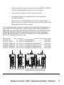
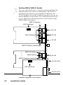
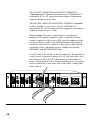
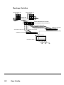
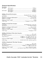
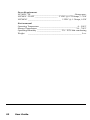
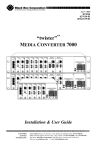
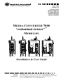
JULY 1999
LE7402C-TX
LH7402C-TX-R2
LH7403C-MMSC-R2
LH7404C-SMSC-R2
LH7403C-MMST-R2
LH7403C-SMST-R2
MEDIA CONVERTER 7000
™
“redundant twister”
MODULES
100 BASE
10 BASE
RESET
PWR
SW
RESET
LK
M
A
I
N
PWR
SW
RESET
LK
P
R
I
AT
AT
LK
LK
S
E
C
MAIN
AT
LK
P
R
I
S
E
C
AT
100 BASE
“redundant twister”
LK
M
A
I
N
AT
100 BASE
“redundant twister”
AT
LK
PWR
SW
AT
SW
SECONDARY
R
X
T
X
MAIN
PWR
RESET
AT
R
X
T
X
AT
SECONDARY
PRIMARY
LK
LK
LK
AT
R
X
T
X
PRIMARY
LK
AT
R
X
T
X
LK
AT
SEC
SEC
Installation & User Guide
CUSTOMER
SUPPORT
INFORMATION
Order toll-free in the U.S. 24 hours, 7 A.M. Monday to midnight Friday: 877-877-BBOX
FREE technical support, 24 hours a day, 7 days a week: Call 724-746-5500 or fax 724-746-0746
Mail order: Black Box Corporation, 1000 Park Drive, Lawrence, PA 15055-1018
Web site: www.blackbox.com • E-mail: [email protected]
© 1999 Black Box Corporation
All rights reserved.
Printed in USA.
Black Box and the Black Box logo are registered trademarks of Black Box Corporation.
All other trademarks appearing in this manual are the property of their owners.
This publication is protected by the copyright laws of the United States and other countries, with
all rights reserved. No part of this publication may be reproduced, stored in a retrieval system,
translated, transcribed, or transmitted, in any form, or by any means manual, electric, electronic,
electromagnetic, mechanical, chemical, optical or otherwise, without prior explicit written
permission of Black Box Corporation.
The information contained in this document is assumed to be correct and current. The
manufacturer is not responsible for errors or omissions and reserves the right to change
specifications at any time without notice.
Table of Contents
Media Converter 7000 “redundant twister” Module
Installation & User Guide
Product Overview ....................................................................................... 4
Installation Guide ...................................................................................... 7
STEP 1: Unpacking the “redundant twister” Module ................... 7
STEP 2: Setting the DIP Switches ............................................... 7
STEP 3: Setting the MDI-II/MDI-X Switch ............................... 10
STEP 4: Installing the “redundant twister” Module .................... 12
STEP 5: Connecting to the Network .......................................... 13
User Guide ............................................................................................... 15
Module LED Operation ............................................................ 15
Reset Push Button .................................................................... 16
Link Loss Carry Forward (LLCF) ............................................ 17
Topology Solutions .................................................................. 18
Technical Specifications ........................................................... 19
Product Safety, EMC and Compliance Statements .................. 21
Overview
The Media Converter 7000 “redundant twister” Module offers the
resiliency of data link redundancy to ensure network integrity with no down
time. This link duplication provides the non-stop networking capability
essential for high priority traffic and mission-critical applications. The
“redundant twister” modules provide full redundant data paths for Ethernet or
Fast Ethernet devices. The Fast Ethernet “redundant twister” modules also
provide 100BASE-TX to FX media conversion. In Dynamic Revovery Mode
(DRM) the “redundant twister” module actively monitors the primary link
and if it fails, automatically activates the secondary link without interruption
to network operation.
The “redundant twister” modules have the following features:
• Can be configured to operate in Dynamic Recovery Mode
(DRM) to ensure session integrity and increased uptime.
• Can be configured to operate in Network Select Mode (NSM)
to redirect and isolate traffic adding extra security.
• Immediately switches over from the primary link to the
secondary link if the primary link fails.
• Can be configured to return automatically to the primary link
after the failure condition is resolved or only upon secondary
failure; or manually switched back to primary after fail-over.
• In addition to providing link and data on the active ports, the
“redundant twister” module can be configured to provide link
or link and redundant transmit data on the non-active port.
• Provides minimal impact on the round trip delay for
communication in half duplex collision domains.
• Fast Ethernet modules demonstrate a maximum loss of 2-3
packets (measured with minimum packet size and minimum
inter-packet gap) during fail-over transition.
• Supports full and half-duplex operation.
• Link Loss Carry Forward* enable/disable functionality.
* Please refer to the page titled “Link Loss Carry Forward (LLCF)” in the User Guide section of
this document for more detailed information.
4
•
All twisted-pair ports are equipped with an MDI-II to MDI-X
switch eliminating the need for crossover cables.
•
Auto-polarity support on all twisted-pair ports.
•
Functions with devices configured for auto-negotiation
(parallel detection).
•
Fused power on each module protects the system from a
short circuit on a module. This prevents a faulty module from
bringing down the entire system.
The “redundant twister” module is available in six models and can be installed in
any Media Converter 7000 chassis. These models each contain a MAIN port, a
PRIMARY port and a SECONDARY port. Redundancy is provided between the
PRIMARY and SECONDARY ports. Because of the size of the “redundant
twister” fiber optic modules, each TX-FX module uses two slots in the chassis.
The TX-TX modules use only one slot.
Model Number
Mbps Connectors ________________ Maximum Supported Link Length
LE7402C-TX
LH7402C-TX-R2
LH7403C-MMSC-R2
LH7404C-SMSC-R2
LH7403C-MMST-R2
LH7403C-SMST-R2
10 BASE
RESET
PWR
SW
LK
M
A
I
N
AT
10
100
100
100
100
100
RJ-45 to redundant RJ-45 ____________ 100m/100m
RJ-45 to redundant RJ-45 ____________ 100m/100m
RJ-45 to redundant FX multimode SC ____ 100m/2km
RJ-45 to redundant FX singlemode SC __ 100m/15km
RJ-45 to redundant FX multimode ST ____ 100m/2km
RJ-45 to redundant FX singlemode ST __ 100m/15km
100 BASE
RESET
PWR
SW
M
A
I
N
AT
RESET
LK
P
R
I
AT
LK
LK
S
E
C
AT
SEC
100 BASE
“redundant twister”
MAIN
AT
LK
P
R
I
100 BASE
“redundant twister”
LK
S
E
C
AT
LK
PWR
SW
AT
SW
SECONDARY
R
X
T
X
MAIN
PWR
RESET
AT
R
X
T
X
AT
SECONDARY
PRIMARY
LK
LK
LK
AT
R
X
T
X
PRIMARY
LK
AT
R
X
T
X
LK
AT
SEC
LE7402C-TX LH7402C-TX-R2 LH7403C-MMSC-R2 LH7403C-MMST-R2
LH7404C-SMSC-R2 LH7403C-SMST-R2
Media Converter 7000 “redundant twister” Modules
5
6
Installation Guide
Installation Guide
Follow the simple steps outlined in this section of the manual to install
and start using your “redundant twister” Module.
1
Unpack the “redundant twister” Module.
Check that the following components have been included with
your order:
• “redundant twister” Module
Your order has been provided with the safest possible packaging,
but shipping damage does occasionally occur. Inspect your order
carefully for damage that may have occurred during shipment.
If you discover any shipping damage, notify the carrier and
follow their instructions for damage and claims. Save the original
shipping carton in case return or storage of the unit is necessary.
RED
LLCF
LINK
AUTO
TX
NOTE: When setting the DIP switches, the UP position is when
the lever of the DIP switch is pushed furthest away from the
circuit board. The DOWN position is when the lever of the DIP
switch is pushed closest to the printed circuit board.
1
2
3
4
5
2
Set the DIP Switches.
A set of 5 DIP switches, located on the module board, provide
user-selectable configurability options for several modes of
operation. These switches are clearly marked on the module’s
printed circuit board. Refer to the table on the next page for the
proper setting of the DIP switches.*
DOWN
UP
Media Converter 7000 “redundant twister” Modules
7
The DIP switches are marked on the printed circuit board and
can be set for the following operational functions:
Switch Name
TX
AUTO
LINK
LLCF
Position*
Operation
UP
Data transmits on both the PRIMARY
and SECONDARY ports simultaneously.
Link on both must be enabled.
DOWN
(default)
Data transmits on the active port only.
UP
Active port automatically reverts
back to the PRIMARY port when
the primary link is re-established.
DOWN
(default)
Active port will not revert back to the
PRIMARY port when a primary link is
re-established until the SECONDARY
link fails. If the SECONDARY link does
not fail, the SECONDARY port remains
active. Use the RESET push button
located on the front of the module to
force the active port back to the
PRIMARY port and clear the SW LED.
UP
Link symbols are sent out on both the
PRIMARY and SECONDARY ports
(i.e. Link is sent out both ports).
DOWN
(default)
Link symbols are sent out on the active
port only. With the LINK switch in this
position, data is not transmitted out the
non-active port regardless of the TX
switch setting.
UP
Link Loss Carry Forward is enabled.
DOWN
(default)
Link Loss Carry Forward is disabled.
* When setting the DIP switches, the UP position is when the lever of the DIP switch is pushed
furthest away from the circuit board. The DOWN position is when the lever of the DIP switch is
pushed closest to the printed circuit board.
8
Installation Guide
RED
UP
Operates in Dynamic Recovery Mode (DRM).
(default) If the PRIMARY link fails, the SECONDARY
port becomes active. Refer to the description
of the AUTO switch.
DOWN Operates in Network Select Mode (NSM).
Use the RESET push button to toggle
between PRIMARY and SECONDARY. In
NSM, the AUTO switch sets the initial
active port on power up. Up is SECONDARY and down is PRIMARY. Note that
the SW LED remains off in the Network
Select Mode.
RED
LLCF
LINK
AUTO
TX
1
2
3
4
5
DIP Switches
RJ-45
RJ-45
RJ-45
RED
LLCF
LINK
AUTO
TX
1
2
3
4
5
DIP Switches
RJ-45
FX SC (ST)
FX SC (ST)
Media Converter 7000 “redundant twister” Modules
9
3
Set the MDI-II/MDI-X Switch.
For every twisted-pair port, a switch is used to implement the
transmit and receive crossover functionality. The switch is
positioned just behind its associated RJ-45 connector. On
TX-FX modules, the switch is hidden from direct view by the
smaller daughter circuit board. Use a small paperclip for easy
access. Refer to the illustration below for the location of the
MDI-II/MDI-X switch(es):
RED
LLCF
LINK
AUTO
TX
1
2
3
4
5
MDI-X Position
DIP Switches
Slide Switches
RJ-45
RJ-45
RJ-45
MDI-II Position (default)
MDI-X Position
Slide Switch
RJ-45
FX SC (ST)
RED
LLCF
LINK
AUTO
TX
1
2
3
4
5
MDI-II Position (default)
DIP Switches
FX SC (ST)
smaller daughter circuit board
10
Installation Guide
The switch connects the transmit and receive signal pairs in
either straight through or crossover configurations.
The signal routing is as follows:
Switch Position
Connection
TX+ to TX+
TX- to TXRX+ to RX+
RX- to RXTX+ to RX+
TX- to RXRX+ to TX+
RX- to TX-
When setting the MDI-II/MDI-X switch, observe the positioning
of the following symbols:
• the parallel symbol (II) indicates a straight through or
parallel connection (default)
• the cross symbol (X) indicates a crossover connection.
These two symbols are clearly marked on the printed circuit
board. Simply slide the switch in the direction of the appropriate
symbol. Because of the smaller space between boards on
TX-FX modules, use a paperclip to reach in and push or pull the
switch toward the appropriate symbol.
Media Converter 7000 “redundant twister” Modules
11
4
Install the “redundant twister” Module.
“redundant twister” modules offer the ease of plug-and-play
installation and are hot-swappable. All modules must be firmly
secured to the chassis before network connections are made.
Follow the simple steps outlined below to install the “redundant
twister” module:
NOTE: Each TX-FX module uses two slots in the chassis.
The TX-TX module uses only one.
• Grasp the module by the front panel as shown.
Card Guide
100 BASE
10 BASE
PWR
10 BASE
PWR
100 BASE
PWR
100 BASE
100 BASE
PWR
PWR
100 BASE
100 BASE
PWR
100 BASE
“redundant twister”
PWR
10 BASE
PWR
“redundant twister”
SW
RESET
SW
TP
TP
LK
LK
M
A
I
N
AT
AT
LK
P
R
I
AT
M
M
LK
AT
R
X
M
M
T
X
TX
LK
R
X
COL
T
X
TX
LK
AT
AT
AT
R
X
S
M
T
X
LK
AT
R
X
S
M
T
X
PWR
AT
RESET
LK
AT
R
X
T
X
SECONDARY
FX
LK
AT
R
X
T
X
LK
AT
R
X
T
X
SW
RESET
PRIMARY
LK R
X
AT
T
X
LK
LK
R
X
AT
T
X
AT
I
“redundant twister”
N
SECONDARY
LK
100 BASE
A
AT
PRIMARY
LK R
X
AT
T
RESET X
PWR
SW
SECONDARY
SEC
R
X
M
M
T
X
IMPORTANT!
Tighten thumb screw
to secure each module firmly
to chassis before making
network connections.
RESET
MAIN
LK
SW
AT
FX
LK
MAIN
PWR
LK
M
FL
BNC
LK
AT
R
X
T
X
AT
S
E
C
LK
LK
P
LK
AT
MAINR
LK
AT
S AT
E
C
LK
I
DISCONNECT ALL POWER
SOURCES BEFORE SERVICING
AC IN
100-240V
50/60Hz
2A
DISCONNECT ALL POWER
SOURCES BEFORE SERVICING
AC IN
100-240V
50/60Hz
2A
AT
PRIMARY
LK R
X
AT MM
T
X
LK SEC
AT
Thumb Screw
Blank Panel
Card Guide
• Insert the module into a slot on the chassis
making sure that the top and bottom edges of the
main module board are aligned with the top and bottom
card guides in the chassis. Do not force the module into the
chassis unnecessarily. It should slide in easily and evenly.
• Slide the module in until the top and bottom edges of the front
panel are flush and even with the top and bottom edges of the
chassis.
• Turn the thumbscrew clockwise until it is snug to secure the
module to the chassis.
• The “redundant twister” module is now properly installed and
ready for connection to the network.
12
Installation Guide
5
Connect to the Network.
A total of three connections must be made on the front panel when
connecting the “redundant twister” module to the network. Be sure
that all modules are firmly secured to the chassis before making
network connections.
• Connect to the MAIN port.
Each “redundant twister” module provides one shielded RJ-45 jack
for 10BASE-T/100BASE-TX connections and supports a maximum
segment length of 100 meters over Category 3, 4 or 5 Twisted-pair
Cable for 10Mbps and Category 5 Twisted-pair Cable for 100Mbps.
Refer to STEP 3 for MDI-II to MDI-X switch functionality. Before
making the proper twisted-pair connection, you must verify the
port configuration of the connected device.
Embedded Parallel Function
Device with Straight Through
TP Port Configuration
1
2
3
6
“redundant twister”
TP Port Configuration
TD+
TDRD+
RD-
TD+
TDRD+
RD-
1
2
3
6
Embedded Crossover Function
“redundant twister”
TP Port Configuration
1
2
3
6
MDI
TD+
TDRD+
RD-
Typical Hub
TP Port Configuration
MDI–X
TD+
TDRD+
RD-
1
2
3
6
A device that is wired straight through, needs one crossover connection:
If the cable is…
… the MDI-II to MDI-X Switch Setting should be
straight through
X
crossover
II
A device that is wired crossover, needs a parallel connection:
If the cable is…
… the MDI-II to MDI-X Switch Setting should be
straight through
II
crossover
X
If you do not know the internal wiring configuration of the
other device’s RJ-45 port, consult the product documentation.
• Connect to the PRIMARY port.
• Connect to the SECONDARY port.
The LE7402C-TX and LH7402C-TX-R2 “redundant twister”
modules provide two additional RJ-45 jacks for 10BASE-T/100BASE-TX
connections and supports a maximum segment length of 100 meters
over Category 3, 4 or 5 Twisted-pair Cable for 10Mbps and Category
5 Twisted-pair Cable for 100Mbps.
Media Converter 7000 “redundant twister” Modules
13
The LH7403C-MMSC-R2 and LH7403C-MMST-R2
“redundant twister” modules provide two sets of 100BASE-FX
multimode SC or ST connectors that support a maximum
segment length of up to 2km.
The LH7404C-SMSC-R2 and LH7403C-SMST-R2 “redundant
twister” modules provide two sets of 100BASE-FX
singlemode SC or ST connectors that suppport a maximum
segment length of up to 15km.
When making fiber optic connections, be sure that the
transmit (TX) optical conductor of the “redundant twister”
module connects to the receive (RX) optical conductor of the
connected device; and be sure that the transmit (TX) optical
conductor of the device connects to the receive (RX) optical
conductor of the “redundant twister” module for both the
PRIMARY and SECONDARY links.
Use the Link (LK) LEDs on the front panel of the module to
verify correct segment connectivity. As you insert the cable
into each port, the LK LED illuminates provided there is
power being applied to the chassis and that there is an active
device connected to the other end of the cable sending idle
link symbols.
100 BASE
100 BASE
PWR
100 BASE
100 BASE
PWR
100 BASE
“redundant twister”
PWR
100 BASE
LK
AT
R
X
M
M
T
X
AT
FX
R
X
T
X
LK
AT
R
X
S
M
T
X
MAIN
LK
AT
AT
P
R
I
AT
R
X
AT
T
X
PWR
AT
RESET
SECONDARY
RESET
MAIN
LK
SW
LK
LK
S
E
C
SEC
14
PWR
LK
M
A
I
N
PWR
SW
RESET
LK
100 BASE
PWR
“redundant twister”
SW
TX
LK
SW
AT
LK
P
R
I
RESET
PRIMARY
LK R
X
AT
T
X
SECONDARY
LK
R
X
AT
T
X
PRIMARY
LK R
X
AT
T
X
AT
AT
LK
AT
LK
S
E
C
AT
SEC
10 BASE
PWR
SW
RESET
MAIN
LK
M
A
I
N
100 BASE
“redundant twister”
SW
RESET
PWR
LK
M
A
I
N
AT
P
R
I
AT
R
X
LK
P
R
I
T
X
PRIMARY
LK R
X
AT
T
X
LK
AT
M
A
I
N
RESET
SECONDARY
AT
SEC
SW
LK
LK
S
E
C
LK
AT
AT
LK
AT
LK
S
E
C
AT
SEC
DISCONNECT ALL POWER
SOURCES BEFORE SERVICING
AC IN
100-240V
50/60Hz
2A
DISCONNECT ALL POWER
SOURCES BEFORE SERVICING
AC IN
100-240V
50/60Hz
2A
User Guide
This section contains more detailed user information regarding the
operating features of your “redundant twister” module.
Module LED Operation
Several LEDs are visible from the front panel. These include SW, PWR,
SECONDARY, LK and AT LEDs. There are separate LK and AT LEDs for
each of the three ports (MAIN, PRIMARY and SECONDARY). Refer to
the table below for a description of each:
The function of each LED is as follows:
LED Label
Color (Status)
Indication
SW
Amber (steady)
SECONDARY port was
the active port at some
point. This LED functions
in Dynamic Recovery
Mode (DRM) only.
PWR
Green (steady)
Power ON
SECONDARY
Green (steady)
ON SECONDARY active
OFF PRIMARY active
(MAIN) LK
Green (steady)
Receive link present
(MAIN) AT
Green (blinking)
Receiving data
(PRIMARY) LK
Green (steady)
Receive link present
(PRIMARY) AT
Green (blinking)
Receiving data
(SECONDARY) LK
Green (steady)
Receive link present
(SECONDARY) AT
Green (blinking)
Receiving data
Media Converter 7000 “redundant twister” Modules
15
Reset Push Button
A small RESET push button is located on the front panel of the “redundant
twister” Module. When used in conjunction with the module’s SW and
SECONDARY LEDs, and the AUTO DIP switch setting, this push button
allows a network administrator to effectively maintain or troubleshoot a
PRIMARY link connection.
Because of its small size and recessed placement within the front panel,
press the RESET push button with the tip of a pointed object. Pushing and
holding the RESET push button has no effect. It is the act of pressing the
push button that causes a reset.
In the event of a PRIMARY link failure, pressing the RESET push button
has the following effect:
If the AUTO switch is UP
and RED switch is UP
The active port automatically reverts
to PRIMARY when primary link is
re-established and pressing the RESET
switch clears the SW LED.
If the AUTO switch is DOWN
and RED switch is UP
The active port does not automatically
revert to PRIMARY when a primary
link is re-established. Pressing the
RESET switch clears the SW LED
and the SECONDARY LED and
forces the PRIMARY port to be the
active port. If the SECONDARY link is
disabled, it reverts to the PRIMARY if
the PRIMARY has a good link.
If there is only a SECONDARY
link, then the SW and SECONDARY
LEDs remain illuminated and pressing
the RESET switch has no effect.
If the RED switch is DOWN
16
User Guide
The module operates in Network Select
Mode (NSM). The RESET push button
toggles the active link between the
PRIMARY and SECONDARY ports.
Note that the SW LED remains off
during Network Select Mode (NSM)
operation.
Link Loss Carry Forward (LLCF)
The “redundant twister” Modules have been designed with an LLCF
function for troubleshooting a remote connection. The modules are shipped
with the LLCF disabled.
When LLCF is enabled, the fiber optic ports as well as the twisted-pair ports
on the module do not transmit a link signal until they receive a link signal
from the opposite port. For example, if LLCF is enabled and two “redundant
twister” Modules are connected via a fiber cable with nothing else connected
to them, the Link LED does not illuminate. When a valid link is established at
the twisted-pair port, a complete connection is accomplished.
The diagram below shows a typical network configuration using a
“redundant twister” Module for remote connectivity:
Management Switch/Hub
Station
w/SNMP
“twister” 7000
Module
“twister” 7000
Module
Switch/Hub Management
w/SNMP
Station
Remote
up to 40km
LED lit = established link
LED unlit = no link
If the fiber connection breaks, or the remote device fails, the “redundant
twister” Module carries that link loss all the way to the switch/hub which
generates a trap to the management station. The administrator can then look
at the module to determine the source of the loss.
Management Switch/Hub
Station
w/SNMP
“twister” 7000
Module
“twister” 7000
Module
Switch/Hub Management
w/SNMP
Station
Broken
Remote
Cable
Link Loss Carried
LED lit = established link
LED unlit = no link
IMPORTANT: When connecting a “redundant twister” Module to a port
that supports auto-negotiation, it is strongly recommended to fix the port
setting to the appropriate speed (100Mbps or 10Mbps) and to either full or
half-duplex. This allows the “redundant twister” Module to sense receive
link and select the active port.
Media Converter 7000 “redundant twister” Modules
17
Topology Solution
Server Cluster “A”
Server Cluster “B”
Servers with
100Mbps NICs
“twister” Media Converter 7000
with “redundant twister” Modules
Secondary F/O Link “B”
Primary F/O Link “A”
Secondary F/O Link “A”
Primary F/O Link “B”
100Mbps F/O Switch
Enterprise Switch
18
User Guide
100Mbps F/O Switch
Technical Specifications
Data Rate
LE7402C Half-duplex ________________________________ 10Mbps
Full-duplex _________________________________ 20Mbps
LH740XC Half-duplex _______________________________ 100Mbps
Full-duplex ________________________________ 200Mbps
10Mbps Twisted-Pair Interface
Connector _____________________________ Shielded RJ-45, 8-pin jack
Impedance ___________________________________ 100 Ohms nominal
Signal Level Output (differential) _______________________ 2.2 to 2.8V
Signal Level Input ________________________________ .3 to 3.1V p-p
Supported Link Length ____________________________________ 100m
Cable Type ______________________________ Category 3, 4, or 5 UTP
100Mbps Twisted-Pair Interface
Connector _____________________________ Shielded RJ-45, 8-pin jack
Impedence ___________________________________ 100 Ohms nominal
Signal Level Output (differential) ______________________ .95 to 1.05V
Signal Level Input _____________________________ 350mV minimum
Supported Link Length ____________________________________ 100m
Cable Type ____________________________________ Category 5 UTP
100Mbps Multimode Fiber Optic Interface
Connector ___________________________________________ ST or SC
RX Input Sensitivity _______________________ -31 dBm peak minimum
Output Power ___________________ -14 dBm to -23.5 dBm (50/125 µm)
______________________ -14 dBm to -20 dBm (62.5/125 µm)
Supported Link Length _______________________ up to 2km full duplex
Cable Type ______________________ 50/125, 62.5/125, 100/140 µm F/O
100Mbps Singlemode Fiber Optic Interface
Connector ___________________________________________ ST or SC
RX Input Sensitivity _______________________ -31 dBm peak minimum
Output Power ______________________ -8 dBm to -15 dBm (9/125 µm)
Supported Link Length ______________________ up to 15km full duplex
Cable Type __________________ 8.3/125, 8.7/125, 9/125, 10/125 µm F/O
Media Converter 7000 “redundant twister” Modules
19
Power Requirements
LE7402C-TX _____________________________________ .5Amps max.
LH7402C-TX-R2 ____________________ 5 VDC @ 0.750Amps, 3.75W
LH740XC _____________________________ 5 VDC @ 1.3Amps, 6.5W
Environmental
Operating Temperature _________________________________ 0 – 50° C
Storage Temperature _________________________________ -30 – 70° C
Operating Humidity _____________________ 5% – 95% non-condensing
Weight
_______________________________________________ 5 oz.
20
User Guide
Product Safety, EMC and Compliance Statements
This equipment complies with the following requirements:
• UL
• CSA
• EN60950 (safety)
• FCC Part 15, Class A
• EN55022 Class A (emissions)
• EN50082-1 (immunity)
• IEEE 802.3/802.3u
• IEC 825-1 Classification
Class 1 Laser Product
Radio Frequency Interference Statements
FCC Radio Frequency Interference Statement
This equipment has been tested and found to comply with the limits for
Class A digital device, pursuant to Part 15 of FCC Rules. These limits are
designed to provide reasonable protection against harmful interference
when the equipment is operated in a commercial environment. This
equipment generates, uses and can radiate radio frequency energy, and if
not installed and used in accordance with the instruction manual, may
cause harmful interference to radio communication. Operation of this
equipment in a residential area is likely to cause harmful interference in
which case the user will be required to correct the interference at his own
expense.
CAUTION: Changes or modifications to this equipment not expressly
approved by the party responsible for compliance could void the user’s
authority to operate the equipment.
Canadian Radio Frequency Interference Statement
This Class A digital apparatus meets all requirements of the Canadian
Interference-Causing Equipment Regulations.
Cet appareil numérique de la classe A respecte toutes les exigences du
Règlement sur le matériel brouilleur du Canada.
Media Converter 7000 “redundant twister” Modules
21
Electrical Safety Statement
Normas Oficiales Mexicanas (NOM)
INSTRUCCIONES DE SEGURIDAD
1. Todas las instrucciones de seguridad y operación deberán ser leídas antes
de que el aparato eléctrico sea operado.
2. Las instrucciones de seguridad y operación deberán ser guardadas para
referencia futura.
3. Todas las advertencias en el aparato eléctrico y en sus instrucciones de
operación deben ser respetadas.
4. Todas las instrucciones de operación y uso deben ser seguidas.
5. El aparato eléctrico no deberá ser usado cerca del agua—por ejemplo,
cerca de la tina de baño, lavabo, sótano mojado o cerca de una alberca, etc.
6. El aparato eléctrico debe ser usado únicamente con carritos o pedestales
que sean recomendados por el fabricante.
7. El aparato eléctrico debe ser montado a la pared o al techo sólo como sea
recomendado por el fabricante.
8. Servicio—El usuario no debe intentar dar servicio al equipo eléctrico
más allá a lo descrito en las instrucciones de operación. Todo otro
servicio deberá ser referido a personal de servicio calificado.
9. El aparato eléctrico debe ser situado de tal manera que su posición no
interfiera su uso. La colocación del aparato eléctrico sobre una cama,
sofá, alfombra o superficie similar puede bloquea la ventilación, no se
debe colocar en libreros o gabinetes que impidan el flujo de aire por
los orificios de ventilación.
10. El equipo eléctrico deber ser situado fuera del alcance de fuentes de calor
como radiadores, registros de calor, estufas u otros aparatos (incluyendo
amplificadores) que producen calor.
22
11. El aparato eléctrico deberá ser connectado a una fuente de poder sólo
del tipo descrito en el instructivo de operación, o como se indique en
el aparato.
12. Precaución debe ser tomada de tal manera que la tierra fisica y la
polarización del equipo no sea eliminada.
13. Los cables de la fuente de poder deben ser guiados de tal manera que
no sean pisados ni pellizcados por objetos colocados sobre o contra
ellos, poniendo particular atención a los contactos y receptáculos donde
salen del aparato.
14. El equipo eléctrico debe ser limpiado únicamente de acuerdo a las
recomendaciones del fabricante.
15. En caso de existir, una antena externa deberá ser localizada lejos de las
lineas de energia.
16. El cable de corriente deberá ser desconectado del cuando el equipo no
sea usado por un largo periodo de tiempo.
17. Cuidado debe ser tomado de tal manera que objectos liquidos no sean
derramados sobre la cubierta u orificios de ventilación.
18. Servicio por personal calificado deberá ser provisto cuando:
A: El cable de poder o el contacto ha sido dañado; u
B: Objectos han caído o líquido ha sido derramado dentro del aparato; o
C: El aparato ha sido expuesto a la lluvia; o
D: El aparato parece no operar normalmente o muestra un cambio en su
desempeño; o
E: El aparato ha sido tirado o su cubierta ha sido dañada.
Media Converter 7000 “redundant twister” Modules
23
© Copyright 1999. Black Box Corporation. All rights reserved.
1000 Park Drive • Lawrence, PA 15055-1018 • 724-746-5500 • Fax 724-746-0746
5660-771111-002 A
7/99