1
HEA33NG
Visit
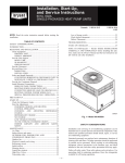
50JS, 50JX
Heat Pump Units
Single-Packaged
& COOLING
www.c,_ier.com
Installation, Start-Up,
and Service Instructions
NOTE:
Read
installation.
the entire
instruction
before
starting
the
OF CONTENTS
CONSIDERATIONS
INTRODUCTION
RECEIVING
.....................................................
t
..........................................................................
AND INSTALLATION
2
..........................................
2
Check Equipment ......................................................................
IDENTIFY
UNIT ................................................................
INSPECT
SHIPMENT
2
2
........................................................
2
Provide Unit Support ................................................................
ROOF CURB .......................................................................
SLAB
MOUNT
GROUND
Provide
2
2
...................................................................
MOUNT
Clearances
2
2
2
INSTALLATION
and Install
................................................................
Ductwork
CONVERTING
(VERTICAL)
DISCHARGE
DISCHARGE
ROUTING
CONNECTIONS
POWER
CONNECTING
ROUTING
SPECIAL
GROUND
INTO
LEAD
CONTROL
POWER
PROCEDURES
FOR
PRE-START-UP
Check
LEADS
UNITS
10
10
TO GROUND
AND
CHARGE
NO CHARGE
LOW
CHARGE
COOLING
INDOOR
MENTS
AIRFLOW
17
17
CHARTS
C99001
18
..................
Fig. 1--Model
AIRFLOW
SAFETY CONSIDERATIONS
19
ADJUST19
20
21
Indoor
21
and motor ........................................................
Installation
hazardous
trained
and qualified
air-conditioning
Untrained
Outdoor
23
by trained
23
equipment,
Reliigerant
circuit ...................................................................
Indoor airflow .........................................................................
24
25
attached
Metering
25
quenching
25
available
Liquid
device
and wiring ................................................
......................................................................
line strainers
Manufacturer
reserves
PC 101
................................................................
the right to discontinue,
CatalOg No. 535-00072
cleaning
Printed in U.S.A.
equipment
and electrical
personnel
should
service
can perform
personnel.
observe
precautions
to the unit, and other
all safety codes.
for all brazing
Form 50JS,JX-4SI
repair,
ba.qic maintenance
When
Only
or service
safety
working
operations.
of
be performed
on air-conditioning
precautions
glasses
functions
should
in the literature,
Wear safety
cloth for unbrazing
or designs
can be
components.
install,
coils and filters. All other operations
Follow
or change at any time, specifications
of air-conditioning
pressure
equipment.
personnel
22
fan .............................................................................
and servicing
due to system
OUTDOOR
COIL, INDOOR COIL, AND
CONDENSATE
DRAIN PAN ...............................................
controls
50JS/50JX
19
Air Filter ..................................................................................
Electrical
INSTRUCTIONS
CAREFULLY AND COMPLETELY before installing this unit.
Also. make sure the Owner's Manual and Service Instructions are
left with the unit after installation.
18
.........................................................................
blower
READ THESE
18
..............................................................................
MAINTENANCE
--
REFRIGERANT
.............................................
AND
25
CHECKLIST
NOTE TO INSTALLER
17
..............................................
CHARGING
............................................................
START-UP
17
....................................................................
TO USE COOLING
25
17
.................................................
ADJUSTING
CHARGE
...............................................................
TROUBLESHOOTING
WIRES (24-V) ............ 13
208-V OPERATION
...15
...........................................................................
REFRIGERANT
25
LUG. 10
Start-Up Adjustments
..............................................................
CHECKING
COOLING
AND HEATING
OPERATION
.................................................................
Thermostat
6
7
UNIT ......................
Leaks ..................................................
CHECKING
Defrost
TO
................................
..........................................................................
CONTROL
25
25
UNITS ......... 5
...................................................................................
for Refrigerant
25
Loss of charge switch .............................................................
Check defrost thermostat ........................................................
4
Provide for Condensate
Disposal .............................................
Install Electrical Connections
...................................................
HIGH-VOLTAGE
25
relay .....................................................................
2
.....................................................
HORIZONTAL
DOWNFLOW
Valves ...................................................................
2
Rig and Place Unit ....................................................................
INSPECTION
......................................................................
START-UP
Flow
2
............................................................
....................................................................
Select
High
Time-delay
TABLE
SAFETY
manual
tags, and labels
that may apply.
and work gloves.
Have
Use
fire extinguisher
operations.
without notice and without incurring
Pg 1
Replaces:
obligations.
50JS,JX-2SI
& 3SI
Improper
nonce,
installation,
or use
can cause
other occurrences,
or
damage
could
property.
service
agency
installer
or agency
alteration,
explosion,
which
your
accessories
adjustment,
fire.
electric
cause serious
Consult
for information
must
service,
mainteshock,
injury
a qualified
or assistance.
when modifying
or
seal.
and poor
Curb
or
kits or
safety
When
see this symbol
you
manuals,
information.
the signal
TION,
and NOTE.
which
will
indicates
death.
This is the safety-alert
on the product
be alert to the potential
Understand
words
in severe
that
Caution
is used
the
personal
could
to identify
most
installation,
unsafe
reliability,
practices,
installation
must
local plumbing
codes.
Warning
be level
which
to within
1/4
Code).
2 in. beyond
the unit
in. (See
61. This
Fig.
The unit may be installed
would
ground
damage.
result in
if local
prepared
must correspond
to
must be sufficient
codes
with gravel
Refer
codes
to provincial
or w,'t_te water codes and other applicable
on all 4 sides of the
when required
minimum
ventilation
Place
service
the
unit
directly
on
outdoor
air through
and
corner
or under an overhead
local
under
a partial
overhang
the unit top.
are shown
in Figs. 2 and
air must be provided.
the outdoor
carpeting
discharge
configurations
for rooftop
RECEIVING
Step
1---Check
IDENTIFY
configuration
slab. Units can be converted
AND
for installation
to downflow
should
levels.
identification
Step
applications.
INSTALLATION
Equipment
obstruction.
The minimum
(such as a normal
The
maximum
number
and serial number
Check
are stamped
this information
against
on the unit
shipping
pa-
pers.
Inspect
for shipping
damage
by
claim
papers
facturer
is not
responsible
all
nearest
Carrier
items
directly
against
prevent loss or damage,
installation.
ROOF
or is torn loose
horizontal
list.
office
all parts
Immediately
Manu
notify
is missing.
in original
packages
units
4--Rig
and Place
Unit
and handling
due to the installation
trained,
qualified
should
handle
When
working
of this equipment
can be hazardous
location
crane
(roofs,
operators
elevated
and ground
for many
structures,
support
staff
and install this equipment.
with
this equipment,
on tags, stickers,
all applicable
precautions
safety
observe
and labels
that might
codes.
precautions
attached
in the
to the equipment,
apply.
Wear safety
shoes
and work
intervals,
all rigging
the
To
should
until
be paid to excessive
wear at hoist hooking
brackets
evidence
attention
points and load
support arexg. Brackets or straps showing any kind of wear in these
arezts must not be used and should be discarded.
INSTALLATION
1. Remove
Install accessory, roof curb in accordance
with curb (See Fig. 5). Install insulatiom
be attached
Slab-mounted
and straps should be visually inspected for any damage,
of wear, structural
deformation,
or cracks. Particular
Unit Support
must
materials.
Prior to initial use, and at monthly
CURB
fln_thing. Ductwork
of a
overhangs,
INSPECTION
in transit.
if any item
is 36
extension
gloves.
removal.
company.
incurred
combustible
reasons
etc.)
Follow
pallet.
its anchorage,
before
to transportation
shipping
leave
from
inspectors
for any damage
Air Conditioning
Step 2--Provide
unit is still on shipping
transportation
Forward
Check
while
to be damaged
it examined
other
and any other safety
SHIPMENT
If unit appears
have
or
literature,
INSPECT
clearance
house overhang)
be at least 4 in. above the highest expected water and runoff
Do not use unit if it has been under water.
Rigging
Only
plate.
it
Be sure that the fan discharge does not
coil. Do not locate the unit in either a
on
/vertical)
UNIT
The unit model
The
coil and discharges
Do not place the unit where water, ice, or snow from an overhang
or roof will damage or flood the unit. Do not install the unit on
INTRODUCTION
in a horizontal-discharge
ground
IMPORTANT: Do not restrict outdoor airflow. An air restriction
at either the outdoor-air inlet or the fan discharge may be
detrimental to compressor life.
performing service or maintenance operations on
turn off main power to unit. Turn off accessory heater
switch if applicable. Electrical shock could cause
injury or death.
a ground-level
on the
level
discharge.
clearances
and
and
in. above
on a slab or placed
for condensate
through the top fan grille.
recirculate
to the outdoor
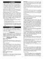
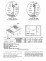
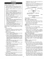
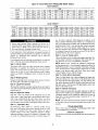
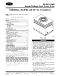
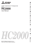
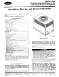
The 50JS and 50JX heat pumps are fully self-contained
and
designed
for outdoor installation
(See Fig. 1). Standard units are
shipped
by
Clearances
3. Adequate
fan draws
either
permit.
The required
outdoor
the casing
to the slab except
partial overhang must not exceed 48 in. For extended
provide a minimum clearance
of 48 in.
Before
system,
power
severe
is
MOUNT
Step 3---Provide
with local building
Electrical
approximately
GROUND
injury, or
or operation.
confortu
(National
with the
for unit drain to function
properly.
Refer to accessory
installation
instructions
for additional
information
as
unit. Do not secure
local codes.
hazards,
and property
which
will
2. The electrical supply provided by the utility
to handle load imposed by this unit.
with NEC
serious
personal
1. The power supply (volts, phase, and hertz)
that specified on unit rating plate.
3. This
supplied
also can result in air leaks
Place the unit on a solid, level concrete pad that is a minimum of
4 in. thick with 2 in. above grade ISee Fig. 71. The slab should
or
CAU
or death.
serious
result in minor personal
injury or product
NOTE is used to highlight
suggestions
enhanced
material
gasketing
MOUNT
extend
WARNING,
injury
cause
symbol/_.
injury.
DANGER,
identifies
result
applied
required.
or in instructions
for personal
--
Danger
a condition
of the unit to the roof curb is critical
gasketing
this product.
SLAB
Recognize
Install
unit performance.
should
necessary
roof curb
The qualified
use only factory-authorized
The gasketing
for a watertight
roof curb. Improperly
or death
installer
IMPORTANT:
with instructions
shipped
cant strips, roofing, and
unit from shipping
carton. Leave top shipping
skid on
the unit as a spreader bar to prevent the rigging straps from
damaging
the unit. If the wood skid is not available,
use a
to curb.
spreader
2
bar of sufficient
length to protect
unit from damage.
/-.
[VAP0_AT_
"l
REOt,qRE3 _/JE,_*_CES
TO _TIm.E
F_OUR_D
B[TW[EN
TOP VIEW
MAIl_
I_OUIRED
lop ,D_ UNiT
D_CT SI_E OF UNII
_1_[
Op_TI
DUCT_
80flO_
_
UNIT
_LECI_IC
_E_I P_EL
NEC
C01t
kt4LLIMETf_S
355 $ il4
5O 8 [?
355 _ 114
12 f [O
914 _ [36
[IN]
00]
06]
00]
50]
_0]
HILtlM[I[RS
_
_ [4l
(_)
00)
CLE/g_k_£
FOff O_A]I_N
AM)
S_5_'K:IN_
MILL;_TIRS
[IN)
91_ 0 1)_ 00)
_14 0 [35 00)
E_p
C_(L AC_[_S SID[
POW[_ [NIR_ S_[
_[_£[PT
fOR N[C _[QU_[_[_TS)
UNIF TOp
_l_f
_PPOSk([
9UCT5
DUCT P_N[L
9r4 0 [)6 00)
9_
0 13_ 00(
3O4 _ IIZ 00]_
_
_!l_
POW(_ ENT_1 51D[
UNll
A_D BLO_ O_ ,_NCR_I[
WALtS AND OIH[R
GROUNDID BU_FAC[S
PO_[I [_T_Y BID[
,MIN_MU_
lOB_ _ t42 OOl
DIST_NC[S
DIMENSIONS
IF _N_T 15 PL_ED
_T_lEM TH[H Sy_T_
IN
[ ]
ARE
L[55
l_
_04 _ [1_ _0_ _O_
WAtL
Pf_fOR_ANCE _YBE CO_RO_I_ED
IN
INCHES
\
--_)i
-IO 2_1
LEFT SIDE VIEW
,_ o _o_s]., oPr
RIGHT SIDE VIEW
FRONT VIEW
x zz o Io _;I
C00137
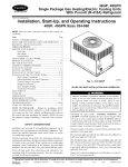
UNIT
UNIT WEIGHT
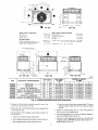
50JS024
5OJSO30
50JS036
50JS042
kg
208/230-1-60
283
128.4
37.02 (940.3)
19.5 (495.3)
13.7 (348.0)
15.0 (381.0)
208/230-1-60
289
131.1
39.02 (991.1)
19.7 (500.4)
13.9 (353.1)
15.0 (381.0)
287
130.2
39.02 (991.1)
19.5 (495.3)
13.7 (348.0)
15.0 (381.0)
CHARACTERISTICS
208/230-1-60,
208/230-3-60
Z
208/230-3-60,
460-3-60
291
132.0
37.02 (940.3)
19.5 (495.3)
13.7 (348.0)
13.0 (330.2)
208/230-1-60,
208/230-3-60,
460-3-60
323
146.5
37.02 (940.3)
19.7 (500.4)
14.0 (355.6)
13.0 (330.2)
299
135.6
41.02 (1041.9)
19.0 (482.6)
13.7 (348.0)
16.0 (406.4)
320
145.2
37.02 (940.3)
19.7 (500.4)
14.0 (355.6)
17.6 (447.0)
328
148.8
37.02 (940.3)
19.7 (500.4)
14.0 (355.6)
16.5 (419.1)
208/230-1-60
5OJXO30
208/230-1-60,
208/230-1-60,
208/230-3-60
208/230-3-60,
460-3-60
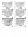
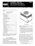
Fig. 2--50JS018-042/50JX024-036
2. Position the lifting bracket _-¢sembly around
unit. Be,_ure the strap does not twist.
3. Place each of the 4 metal
in the composite
lever
lifting brackets
the b_e
into the rigging
of the
holds
strapping
of tension
b. Feed strapping
c. Pull strapping
Unit Dimensions
d. Snap lever
strapping,
outward.
5. Tighten
pan.
4. Thread lifting bracket
unit as follows:
a. Open
X
208/230-1-60,
50JX024
50JX036
Ib
UNIT HEIGHT
IN. (MM)
"A"
ELECTRICAL
50JS018
CENTER OF GRAVITY
IN. (MM)
Y
through
through
around
bottom
perimeter
of
tension
tension
(ratchet
as shown
buckle
unit taut.
in Fig. 8.
7. Attach
lifting
the 2 safety
brackets.
brackets
until
clevis
bracket
(See
straps
buckle.
To release
latch, lift lever, and pull webbing
buckle
field-supplied
4 rigging
safety
in the rigging
hole in the lifting
typel.
buckle
the tension
must be secure
6. Attach
buckle
down to lock strap in tension
squeeze
it is taut. Lifting
brackets
holds.
or hook
of sufficient
strength
to
(See Fig. 9).
directly
DO NOT
Fig. 9).
to the clevis or hook
attach
the safety
straps
at the
to the
illti111
illlllll
'
WI IIIII
402
0 _NtNG
oFo
o ..
c,......
t
tt
14 6_
i
i
3_I 3
{i) _71
[43 BSI
t
RE_
¢:I.,EARAiV_$TO CCI,_US_
TOP VIEW
'
It) 8))
REAR VIEW
MAltMILLIMETERS
tIN]
355 6 [14 00]
50 8 (20Q)
355 6 [14 OQ]
IZ 7 {0 50]
_14
_ [36 00)
TOp 1_ U_lf
DUCt 510£ OF UN)I
SIDE OPPOSIT[
OUCI_
BOfTO_ O( UNll
EL[CTRIC
HEAT PANEL
W)LLIMETERS
tIN]
1066 8 [4Z O0]
914 0 [36 OO]
BETWEEN UNITS
POWER [NIRY
SIDE
g_IT AND UNGROUNDED SURFACES
PO_R
[NTRf
SlOi
gNll AND BLOCK OR CONCp[I[
WALLS AND O(HER
GROUNDED SURFACES
POWER E_TRY SIDE
MILtIM[IERS
(INI
91_ O [SG 00)
91_ _ [36 DOJ
EV_P
CO(L ACC{SS SIDE
PO_[R {NT_T SIOE
[{XCEPF FO_ N[£ REOUIR_MENIS)
UNIT lop
S_OE OPPOSITE DUCTS
9UCf PANEL
IMINIMUW
1066 8 [4_ 00)
OISIAHCESiF
DIWEHSIONS
UNIT IS
SYSTEWIHEN
IN {] ARt
914 _ [36 0_)
914 Q [)6 0_)
)04 8 [(_ 60)1
PLACED LESS [HAN 304 B [1_ 00] FROW (ALL
STSTE_ PERFORMA#CE WATBE COmPrOMISeD
kN (NCHES
t
I(Ii
IIIIII I
lit!
IIIIII
188]
plA _OLE
_ONI_0L [WIRy
,%
"=
i
I
[o _o)
LEFT SIDE
RIGHT SIDE VIEW
VIEW
000136
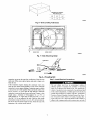
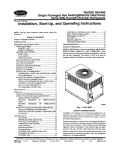
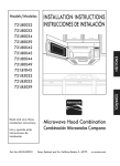
UNIT
ELECTRICAL
UNIT HEIGHT
IN. (MM)
UNIT WEIGHT
CHARACTERISTICS
X
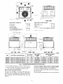
50JS048
208/230-1-60,
208/230-3-60,
460-3-60
Ib
353
kg
160.1
38,98 (990.2)
5OJSO6O
208/230-1-60,
208/230-3-60,
460-3-60
418
189.6
38.98 (990.2)
5OJX042
208/230-1-60,
208/230-3-60,
460-3-60
350
158.8
50JX048
208/230-1-60,
208/230-3-60,
460-3-60
315
5OJX060
208/230-1-60,
208/230-3-60,
460-3-60
428
lifting point directly
over the unit's
9. Lift unit. When unit is directly
2 safety
Step
straps.
_Select
The design
accordance
non-residence
Lower
19.9 (505.5)
17.0 (431.8)
19.9 (505.5)
15.7 (398,8)
17.0 (431.8)
40.98 (1040.9)
19.9 (505.5)
15.7 (398,8)
16.6 (421.6)
170.1
40.98 (1040.9)
19.9 (505.5)
15.7 (398.8)
18.0 (487,2)
194.1
42.98 (1091.7)
19.9 (505.5)
15.7 (398.8)
17.6 (447,0)
of gravity.
over the roof curb, remove
the equipment
and Install
center
90A or residence
ordinances.
type,
according
the
NFPA
and ventilating
90B
and/or
systems,
local
codes
to ASHRAE
tion, and Air Conditioning
The unit has duct flanges
the side of the unit.
Ouctwork
type air conditioning
Unit Dimensions
Select and size ductwork,
onto the roof curb.
and installation
of the duct system
must be
with the standards
of the NFPA for installation
Z
15.7 (398,8)
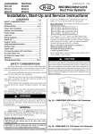
Fig. 3---50JS048-060/50JX042-060
8. Position
CENTER OF GRAVITY
IN. (MM)
Y
in
of
When
NFPA
and
4
designing
supply-air
(American
registers,
Society
Engineers)
and return
of Heating,
recommendations.
on the supply- and return-air
and installing
air _milles
Refrigera-
ductwork,
consider
openings
on
the following:
1
2
Y
Z
3
X
C00071
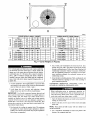
CORNER
Unit
o
1=3
•
-o
o
:_
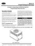
WEIGHTS (SMALL
18
24
"o
0
36
42
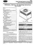
CORNER WEIGHTS
(LARGE CABINET)
Total Weight
283
289
287
291
323
03
Comer Weight 1
67
56
66
54
67
55
83
55
Total Weight
Comer Weight 1
353
76
418
90
---
i
105
62
106
63
107
78
Comer Weight
nit
2
Comer Weight
4
Weight 3
48
49
132
96
60
58
56
t 14
---
Comer
Weight
2
65
53
Comer
Weight
3
103
61
104
62
Corner
Weight
4
CORNER
o
CABINET)
30
WEIGHTS
(Small
Unit
24
_O
Cabinetl
_{_
Total Weiaht
299
320
328
CORNER WEIGHTS
tLaroe Cahinel)
m
--
I °m
Unit
Total Weinht
42
350
48
375
60
428
Comer Weiaht 1
75
81
92
3;
_
Comer Weight 3
Comer Weight 2
Comer Weight 4
95
49
131
102
52
t 40
116
60
160
--
Comer Weiaht 1
63
63
64
--
--
Comer Weight 2
62
74
76
--
--
Comer Weight 3
56
56
58
--
--
Comer Weight 4
118
127
130
--
--
x
l
Fig. 4---Corner Weights (in Pounds)
4. Seal,
insulate,
insulate
For vertical
supply
into ductwork
degree
space.
a grille
units, tools
serious
turn in the return
conditioned
then
and return
and cause
injury
ductwork
If a 90 degree
of sufficient
or parts could
or death.
between
elbow
strength
the unit
cannot
and
Install
density
drop
through conditioned
a 90
Conditioning
and the
be installed,
should
mum
be
2. Avoid
abrupt
change
in Tables
1 and 2.
duct
increases
and
size
in duct size adversely
IMPORTANT:
Use
flexible
unit to prevent tr,'msmission
ensure
weather
tight and
installed,
usd fireproof
affects
connectors
of vibration.
airtight seal.
canvas
(or similar
reductions.
DOWNFLOW
heat
resistant
Before
system,
duct connector
from electric
heater
3. Size ductwork
(or sheet metal sleeve)
material)
must extend
1. Open
starting
air quantity
(cfm).
and
air
Flash,
weatherproof,
and
in wall or roof
according
DISCHARGE
UNITS
to
practices.
HORIZONTAL
(VERTICAL)
DISCHARGE
TO
UNITS
performing
service or maintenance
operations
turn off main power to unit and install lockout
all electrical
any service
disconnects
and install
on
tag.
Elec-
lockout
tag before
return
and supply
work.
2. Remove side duct covers
knock outs.
24-in.
element.
for cooling
heating
Turn off accessory
heater power switch if applicable.
trical shock could cause serious injury or death.
to
is
connector
between
ductwork
and unit discharge
connection.
If
flexible duct is used, insert a sheet metal sleeve inside duct. Heat
resistant
residential
ISMACNA)
{ACCA/mini-
Tf
°
'_
•
r!_l k,
I-.I,1,11d_1
and
Use suitable gaskets
When electric
heat
Association
Association
structure.
duct openings
Abrupt
ductwork
for
Seal,
passing
latest Sheet Metal and Air
Contractors
standards
construction
CONVERTING
air performance.
between
Follow
ductwork.
all ductwork
systems.
vibration-isolate
1. All units should have field-supplied
filters or accessory filter
rack installed in the return-air side of the unit. Recommended
are shown
installation
all external
barrier
National
5. Secure all ducts to building
good
for filters
spaces.
Contractors
conditioning
duct.
sizes
with a vapor
and Air Conditioning
installed to prevent objects from falling into the conditioned
space. Units with electric heaters require 90 degree elbow in
supply
and weatherproof
and cover
to access
bottom
NOTE: These panels are held in place with tabs similar to an
electrical knockout.
The minimum
air quantity
for proper electric heater operation
is listed in
Tables 3 and 4. Heater limit switches may trip at air quantities
below those recommended.
3. Use a screwdriver and hammer to remove the panels in the
bottom of the composite unit base.
5
VAC unrl
base "_
_
_(NOTE A)
supplied
_
_
Ir_ulaUon
Roofir_ material
field suPPlied m
(field
supplied)
eu_i
work
field su_l_d
_Cant
Roof
Curb
for Small
strip
Cabinet
field supplied
Roof Curb for Large Cabinet
Note A: When unit mounting screw is used,
retainer bracket must also be used.
Note A: When unitmounting screwis used,
retainerbracketmustalsobe used.
R/A
S/A
Insulated
Gasket around
deck pan
outer edge
C00076
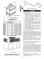
UNIT SIZE
50JS018-042
50JS048-060
IN. (MM)
B
IN. (MM)
C
IN. (MM)
D
IN. (MM)
CPRFCURB006A00
8 (203)
11 (279)
161/2 (419)
28-3/4 (730)
CPRFCURS007A00
14 (386)
11 (279)
161/2 (419)
28-3/4 (730)
CPRFCURB008A00
8 (203)
16 3/16 (411)
17 3/8 (441)
40-1/4 (1022)
CPRFCURB009A00
14 (356)
16 3/16 (411)
17 3/8 (441)
40-1/4 (1022)
ODS CATALOG
50JX024-036
50JX042-060
A
NUMBER
NOTES:
1.
2.
3.
4.
5.
6.
7.
8.
9.
Roof curb must be set up for unit being installed.
Seal strip must be applied, as requiRd, to unit being installed.
Dimensions in ( ) are in millimeters.
Roof curb is made of 16-gage steel.
Table lists only the dimensions, per part number, that have changed.
Attach ductwork to curb (flanges of duct rest on curb).
Insulated panels: t-in. thick fiberglass 1 Ib density.
Dimensions are in inches.
When unit mounting screw is used (see Note A, a retainer bracket must be used as well• This bracket must also be used when required by code for hurricane or
seismic conditions. This bracket is available through MicrornetL
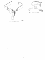
Fig. 5_Roof
4. Ensure
the side duct covers
horizontal
air openings.
NOTE:
change
Avoid
abrupt
in duct size
duct size
adversely
are
in place
to block
off the
Curb Dimensions
The
units
fitting
increases
affects
and reductions.
Abrupt
permitted)
tions. Install
Step
C0---Provide
NOTE:
with
Ensure
local codes,
for Condensate
that condensate-water
restrictions,
Disposal
disposal
and practices.
methods
comply
of condensate
on the compressor
water can be drained
(where
air pedormance.
dispose
that exits
directly
a field-supplied
a 3/4
in. NPT
end of the unit.
onto the roof in rooftop
or onto a gravel
connection to ensure
the trap is at least
through
apron
condensate
in ground
female
Condensate
installations
level installa-
trap at end of condensate
proper drainage. Make sure that the outlet of
1 in. lower than the drain-pan
condensate
MAXIMUM ALLOWABLE
DIFFERENCE (in.)
B
A-B
B-C
A-C
1/4
1/4
1/4
C99065
Fig. 6_Unit
Leveling Tolerances
2 w
±
m
t
EVA,RCOIL
COND.COIL
C99096
Fig. 7--Slab
Mounting
Detail
FEED
C99067
Fig. 8---Threading
connection
to prevent
the pan from
with water. When using a gravel
from the unit.
If the
from
installation
apron,
draining
to ensure proper
as an accessory
is at least
connection
trough
1 in. lower
to prevent
using
than
the pan from
a minimum
of
the trap
make sure it slopes
Belt
Step 7--Install
Electrical Connections
away
water
away
The
unit
cabinet
electrical
Condensate
Make sure that the outlet of the
injury if an electrical
consist of an electrical
the unit
in the control
trap is available
drain-pan
overflowing.
field-supplied
condensate
Connect
3/4
in.
a drain
PVC
or
ground
downward
adhere
Be sure to check the drain
beginning
of the cooling
trough
season
10 ft. of horizontal
for leaks.
start-up.
Prime
run.
the trap at the
an
uninterrupted,
the
unbroken
possibility
of personal
fault should occur. This _ound
may
wire connected
to the unit ground lug
compartment,
tion Association
1 in. every
have
to minimize
or conduit
approved
for electrical
ground when installed in accordance
with NEC, ANSI/NFPA
American
National Standards
Institute/National
Fire Protec
field-supplied
3/4 -in. copper pipe at outlet end of the 2 in. trap
(See Fig. 12). Do not undersize
the tube. Pitch the drain trough
at a slope of at least
must
2-in. trap at the condensate
drainage.
or is field-supplied.
Prime
the condensate
the unit. install a field-supplied
connection
trap
requires
overflowing.
(latest
edition)
(in Canada,
trical Code CSA C22.1 ) and local electrical
to this warning
could
result
in serious
Canadian
codes.
injury
Elec-
Failure
to
or death.
C00139
Fig. 10_Typical
Installation
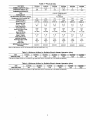
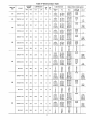
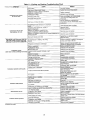
Table 1--Physical
UNIT SIZE
NOMINAL CAPACITY
(ton)
OPERATING WEIGHT (lb.)
COMPRESSOR QUANTITY
Data
50JS018
50JS024
50JS030
50JS036
50JS042
50JS048
1-1/2
2
2-1/2
3
3-1/2
4
5
283
289
287
291
323
353
418
1
TYPE
RECIPROCATING
COMPRESSOR
REFRIGERANT
REFRIGERANT
METERING
50JS060
SCROLL COMPRESSOR
I
R-22
DEVICE
AccuRate_
6.5
5.3
5.6
7.6
8.0
7.85
9.3
ORIFICE ID (in.)
0.053
0.061
0.068
0.078
0.078
0.088
0,093
ORIFICE OD (in.)
OUTDOOR COIL
Rows,.. Fins/in,
Face Area (sq, ft.)
OUTDOOR FAN
0.040
0.035 (2)
0.042 (2)
0.046 (2)
0.052 (2)
0.057 (2)
0.061 (2)
1...17
10.2
1...17
12.0
1...17
12,0
2...17
10.3
2...17
10.3
2...17
11.6
2...17
11.6
2400
22
1/8 (825)
2400
22
1/8 (825)
2400
22
1_ (825)
2800
22
1_ (1100)
2400
22
1/8 (625)
3300
22
1/4 (1100)
3300
22
1_ (1100)
2...15
3.7
2...15
3.7
3...15
3.7
3..,15
3.7
4..,15
3.7
3...15
4.7
4...15
4.7
700
IOXlO
800
10X10
1000
10X10
1200
11X10
1250
11X16
3/4
1600
11X10
3/4
2000
11X10
20X20X1
20X20X1
20X2OX1
20X24X1
24X30X1
24X30X1
24X30X1
Refrigerant
(R-22) Quantity (Ib,)
Nominal Airflow (CFM)
Diameter
Motor HP (RPM)
INDOOR COIL
Rowe.., Fins/in.
Face Area (sq. ft.)
INDOOR BLOWER
Nominal Airflow (CFM)
Size (in,)
Motor (HP)
RETURN-AIR FILTERS (in.)
throwaway
8
Table 2--Physical
UNIT SIZE
NOMINAL CAPACITY
(ton)
OPERATING WEIGHT (lb.)
COMPRESSOR QUANTITY
Data
50JX024
50JX030
50JX036
50JX042
2
2-1/2
3
3-1/2
299
320
328
350
5
428
1
TYPE
SCROLL COMPRESSOR
REFRIGERANT
REFRIGERANT
50JX060
50JX048
375
R-22
METERING
DEVICE
AccuRate_
5.5
6.4
7.0
10.8
10.1
12.3
ORIFICE ID (in,)
0.065
0.073
0.076
0.080
0.088
0.093
ORIFICE OD (in.)
OUTDOOR COIL
Rows... Fins/in.
Face Area (sq. ft.)
OUTDOOR FAN
Nominal Airflow (CFM)
Diameter
Motor HP (RPM)
INDOOR COIL
Rows... Fins/in.
0.037 (2)
0.043 (2)
0.040 (2)
0.052 (2)
0.057 (2)
0,063 (2)
1...17
13.7
2...17
10.3
2-.17
10.3
2.,,17
13.7
2...17
13.7
2._17
15.7
2350
22
1/8 (825)
2350
22
1/8 (825)
2800
22
1/4 (1100)
2800
22
1/8 (825)
3300
22
1/4(1100)
3300
22
1/4(1100)
3,,.15
3,7
3.,.15
3.7
4...15
3.7
4-.15
4.7
4...15
4.7
4.,.15
5.7
800
10X10
1/4
1000
10X10
1/4
1200
10X10
1/2
1400
11X10
1/2
1450
11X10
1/2
1750
11X10
1
20X20X1
20X20X1
20X24X1
24X30X1
24X30X1
Refrigerant
(R-22) Quantity (lb.)
Face Area (sq. ft.)
INDOOR BLOWER
Nominal Airflow (CFM)
Size (in.)
Motor (HP)
RETURN-AIR FILTERS (in.)
throwaway
NOTE: Air filter pressure drop for non-standard
24X30Xl
filters must not exceed 0.08 in. wg.
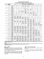
Table 3_Minimum
Airflow for Reliable Electric Heater Operation (Cfm)
SIZE
50JS018
50JS024
50JS030
50JS036
50JS042
50JS048
50JS060
AIR FLOW (CFM)
650
800
1000"
1200
1400
1600
2000
• The 030 size models must be run on medium or highspeed when usedin conjunctionwith 15 kwelectdc heat accessory
Table 4_Minimum
SIZE
AIRFLOW
(CFM)
Airflow for Reliable Electric Heater Operation (Cfm)
50JX024
50JXO30
50JX036
50JX042
50JX048
50JXO6O
800
1000"
1200
1400
1600
2000
* The 030 size modelsmust be run on medium or high speed when usedin conjunction with 15 kw electdc heat accessory
9
1" (25ram)
MIN.
TRAP
(36" 54"/
OUTLET ]
+
2" (50ram)
MIN.
C99013
Fig. 12_ondensate
OETAIL A
SCALF 0250
Failure to follow these precautions
the unit being installed:
1. Make all electrical connections
ANSI/NFPA
Canadian
L
SAFETY
CLEVIS
STRAPS
TO
AT 4 RIGGING
codes.
BRACKETS
2.
PLACE RIGGING
BRACKET
ASSEMBLY
{N 4
RIGGING
HOLES AND iNSTALL TIE DOWN STRAP
AROUND
PERIMETER
OF UNIT AN{] THROUGH
SPACE IN BRACKET
ASSEMBLY
SEE DETAIL A
UNIT
Size
Use
only
voltage
and
Code
copper
local
in.
19.5
ram.
495.3
in.
mm.
local
50JS018
kg
138.4
16.75
425.5
and/or
50JS024
311
141.1
18.5
469.9
16.75
425,5
50JS03O
309
140.2
19.5
495.3
1730
444.5
50JS036
313
142.0
19.5
495.3
17.75
450.9
50JS042
345
156.4
19.5
495.3
17.75
450.9
50JSO48
375
170.1
20.5
520.7
20.62
523.8
5OJS060
440
199.6
19,5
4953
19.75
501.7
50JX024
321
145.6
19.0
482.6
18.25
463.6
50JX030
342
155.2
20.0
508
19.25
489
50JX036
350
158.8
20.0
508
19.0
482.6
50JX042
372
168.8
21.0
533.4
20.5
520.7
50JX048
377
171.0
20.0
508
21.25
539.8
50JX060
450
204.2
21.0
533.4
20.0
508.0
Part
range
power
phase
4. Insulate
within
1 and
applicable
local
for
connections
switch
between
and unit.
power to unit is within
on unit rating
are balanced
plate.
operating
On 3-phase
within 2 percent.
for correction
DO
Consult
of improper
voltage
imbalance.
low-voltage
conduit
conduit
NEC
codes
all electrical
connecCSA standard C22.1
disconnect
WIRE.
indicated
company
with
electrical
to
diagram.
conductor
units, ensure phases
Ib
305
Fig, 9_Suggested
Electrical
Refer to unit wiring
3. Be sure that high-voltage
B
A
in accordance
edition)
field supplied electrical
NOT USE ALUMINUM
C99075
MAXIMUM WEIGHT
INCLUDES SHIPPING SKID
could result in damage
governing
such wiring. In Canada,
tions must be in accordance
with
TIGHTEN
STRAPPING
SECURELY
WITH TENS}ON
BUCKLE
INSTALL
RIGGING
(latest
Trap
wires
as high-voltage
5. Do not damage
voltage
control
contained
wires are in same
wires.
internal
any panel to mount
HIGH-VOLTAGE
for highest
when low-voltage
components
electrical
when drilling
hardware,
conduiL
through
etc.
CONNECTIONS
The unit must have a separate electrical service with a fieldsupplied, waterproof disconnect switch mounted at, or within sight
from the unit. Refer to the unit rating plate, NEC and local codes
for maximum fuse/circuit breaker size and minimum circuit amps
(ampacity) for wire sizing (See Tables 5 and 6 for electrical data).
Rigging
The field-supplied disconnect may be mounted on the unit over the
high-voltage inlet hole (See Fig. 2 and 3).
If the unit has an electric heater, a second disconnect may be
required. Consult the Installation, Start-Up, and Service Instructions provided with the accessory for electrical service connections.
Operation of unit on improper line voltage constitutes abuse and
may cause unit damage that could affect warranty.
ROUTING
POWER
LEADS
INTO
UNIT
Use only copper wire between
disconnect
and unit. The highvoltage leads should be in a conduit until they enter the duct panel;
conduit
terntination
high-voltage
entry
at the duct panel must be watertight.
leads through
side panel.
the power entry knockout
See Fig. 2 and 3 for location
and size. When
leads are inside the unit. run leads up the high-voltage
the line wiring splice box (See Fig. 13-19).
Horizontal Duct Covers
connect
leads
connect
|8).
the leads to the black,
to the
black
and yellow
yellow,
Run the
on the power
raceway
the
to
For single-phase
units,
wives: for 3-phase
units,
and blue wires
(See
Fig.
C99030
CONNECTING
Fig. 11--50JX with Duct Covers On
(Unit Shown with Optional Louvered Grille)
Connect
wiring
10
GROUND
the ground
splice
LEAD TO GROUND
lead to the chassis
box ISee
Fig. 18).
LUG
using the ground
lug in the
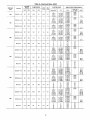
Table 5--Electrical
UNIT 50JS
SIZE
018
024
V-PH-HZ
208/230-1-60
208/230-1-60
VOLTAGE
RANGE
COMPRESSOR
MIN
MAX
RLA
LRA
187
253
90
48
187
253
12.6
61
OFM
FLA
09
0.9
Data--50JS
IFM
FLA
FLA
MCA
FUSE OR
CKT BKR
1.8
./3.8/8.0
5 4/72
7.5/100
./_
18.1/20.8
26.0/300
361/417
14.0/14,0
36.5/40.0
46.4/51.5
59.1/66.0
20/20
40/45
50/60
2.0
-/3.8/5.0
5.477.2
7.5/100
_/_
18.1/20.6
26.0/30.0
36.1/41.7
18.9/18.9
41.5/44.9
51.4/56.4
64.0/71.0
25/25
45/45
66/-
_/.
18.1/20.8
26.0/30.0
36.1/41.7
54.2/62.5
21.3/21.3
48.8/47.3
53.8/58.8
66.4/73.4
89.0/99.4
25/25
45/50
20/20
30/35
45/50
60/-
253
14.7
82
0.9
2.0
208/230-3--50
187
253
9.9
78
0.9
2.0
/3.6/5.0
7.5/10.0
11.3/15.0
./10.4/12,0
20.8/24.1
31.3/36.1
15.3/15.3
28.3/30.3
41.3/45.3
54.4/60.4
-/18.1/20.8
26.0/30.0
36.1/41.7
54.2/62.5
26.6/26.6
49.2/52.6
59.1/64.1
71.7/78.7
94.3/104.7
./o
10.4/12.0
31.3/36.1
36.1/41.7
18.0/18.0
31.0/33/0
44.0/48.0
57.1/63.1
25/25
35/35
45/50
60/-
9.6
17.1
24.6
32.1
15
20
25
35
206/230-1 _0
167
253
16.8
82
1.5
4.1
208/230-3-50
187
253
9.9
85
1.5
4.1
-/9.8/5.0
7.5/10.0
11.3/15.0
1.9
-/5
10
15
./o
18.1/20.6
26.6/30.0
36.1/41.7
54.2/62.5
72.2/83.3
30.5/30.5
53.0/66.5
62.9/68.0
75.6/62.5
98.1/168.6
120.7/134.6
40/40
60/60
3.8
-/3/8/5.0
5.4/7.2
7.5/10.0
11,3/15.0
15.0/20.0
3.8
-/3.8/5.0
7.5/10.0
11.3/15.0
15.0/19.9
./o
10.4/12.0
29.8/24.1
31.3/36.1
41.6/48.0
20.2/20.2
33,2/35.2
46.3/50.3
59.3/65.3
72.2/60.2
25/25
40/40
50/66
60/-
./.
5
10
15
20.0
-/6,0
12,0
18.0
24.1
11.0
18.5
26.0
33.5
41.0
15
20
30
35
45
18.1/20.8
26.0/30.0
36.1/41.7
54.2/62,5
72,2/83.3
35.5/35.5
58.1/61.5
68.0/73.0
60.6/87.6
103.2/113.6
125.6/139.7
45/45
3/8/5.0
5.4,'7.2
7.5/10.0
11.3/15.0
15.0/19.9
o/.
3,8/6.0
7.5/10.0
11.3/15.0
15.0/20.0
-/10,4/12.0
20.8/24.1
31.3/36.1
41.6/48.0
22.6/22.6
35,7/37.7
48,7/52,7
61,7/67,7
74,6/82.6
30/30
40/40
50/60
1.8
-/5
10
15
20
6,0
12.6
18.9
24.1
11.5
19.0
26.5
34.0
41.5
15
20
30
35
45
-/18.1/20.8
26.0F._.0
36.1/41.7
54.2/62.5
72.2/83.3
43.7/43.7
66.3/69.7
76.2/81.2
88.6/95.8
111.4/121.8
134.6/147/9
60/60
6.2
-/3.8/5.0
5.4/7.2
7.5/10.0
11.3/15.0
15.0/20.0
-!10.4/12.0
20.8/24.1
31.3/36.1
41.6/48.0
32.0/32.0
46.6/47.0
58.6/62.1
71.1/77.1
83.9/91.9
40/40
50/50
6.2
-/3.8/5.0
7.5/10,0
11.3/15.0
15.0/19.9
3.2
-/5
10
15
20
6.0
12.0
18.0
24.1
14.0
21.5
29.0
36.6
44.1
20
25
30
40
45
208/230-3-60
460-3-60
208/230-1-60
208/230-3-60
460-3-60
208/230-1-60
O6O
205/2_3-50
460-3-60
187
187
414
187
187
414
167
187
414
606
253
253
506
253
253
506
253
253
506
5.5
20.6
12.4
6.7
24.4
14.1
7.1
28,8
19.4
8.0
40
115
90
45
140
105
53
166
125
63
0.8
0.9
0.9
0.8
1.8
1.5
3.5
1.5
3.5
0.8
1.5
1.5
0.8
11
-/70
70/70
70/80
90/100
-/9.8/5.0
5.4/7.2
7.5/10.0
11.5/15.0
414
MOCP
70/80
187
./o
6.0
12.0
18.0
SUPPLY
60/70
208/230-1-60
208/230-1-60
048
SINGLE POINT POWER
-/3.8/5.0
5.4/7/3
7.5/10.0
11.3/15.0
460-3._60
042
HEAT
Nominal
Kw o
030
036
ELECTRIC
35/35
50/60
-/70
70/80
60/80
100/110
-0/70
80/90
80/90
100/110
125/150
-/70
80/90
70/70
90/90
90/100
110/125
150/150
70/70
80/90
70/80
100/110
100/110
125/125
150/150
°
60/70
80/80
90/100
Table 6--Electrical
UNIT 50JX
SIZE
024
V-PH-HZ
VOLTAGE
RANGE
MIN
208/230
140
187
MAX
253
Data---50JX
COMPRESSOR
ELECTRIC
OEM
FLA
RLA
10.8
FLA
MCA
56
43.8/5.0
5.4/7.2
7,5/10.0
41/81/20.8
26.0/30.0
36.1/41.7
16.4/16.4
39.0/42.4
48.9/539
61.5/68.5
20/20
40/45
60/60
3.8/5.0
5.4/7.2
7,5/10.0
11,3/15.0
18.1/20.8
26.0/30.0
36.1/41,7
54.2/62,5
20.5/20.5
43,1/46.5
53.0/58,0
65.6/72.6
88.2/98.6
25/25
45/50
0.90
2.0
187
253
14.0
73
0.9
2.1
208/230-3-50
187
253
10.4
63
0,9
2.1
43/5/5,0
7.5/10,0
11.3/15.0
-/10A/12,0
20.8/24.1
31.3/36.1
16.0/16.0
29.0/31.0
42.1/46.1
55.1/61 1
20/20
35/35
45/50
-/18.1/20.8
26.0/30.0
36.1/41.7
54.2/62.5
26.1/26.1
48.6/52.1
58.6/636
71.2/78.2
93.8/104.2
35/35
50/60
-/10.4/12.0
36.1/41.7
31.3/36.1
19.2/19.2
32.2/34.2
45.2/49.3
58.3/64.3
25/25
35/35
50/50
9.6
17.1
24.6
32.1
15
20
25
35
208/230-1-50
187
253
16.7
97
1.6
3.6
-/3.8/5.0
5.4/7.2
7,5/10.0
11.3/15.0
208/230-3-60
187
253
11.2
75
1.6
3.6
43.8/5.0
7.5/10.0
11.3/15,0
460-3-60
414
506
5.4
37.5
0.9
1.9
-/5
10
15
418.1/20.8
26,0/30.0
36.1/41,7
54,2/62.5
72.2/83,3
28.0/28.0
50,6/84.0
60.5/65.5
73.1/80.1
95,7/106,1
118.3/132,2
35/35
63/60
4.1
-/3.8/5.0
5.4/7.2
7,5/10,0
11.3/15.0
15.0/20.0
3.8/5.0
7,5/10,0
11,3/15.0
15.0/20.0
10.4/12.0
20.8/24.1
31.3/36.1
41,6/48,0
20,5/20.5
33,5/35.5
46.6/50.6
59.6/65.6
72.5/80.5
25/25
40/40
50/60
2.0
45
10
15
20
46
12
18
24.1
10.2
17.7
25,2
32,7
40.2
15
20
30
35
45
-/18.1/30.8
26,0/30.0
36.1/41,7
54.2/62.5
72.2/83.0
34.9/34.9
57.4/60.9
67.3/'72.4
80.0/86.9
102.5/113.0
125.1/139.0
45/45
4.1
43.3/5.0
5.4/7,2
7.5/10,0
11.3/15.0
15,0/20.0
4.1
-/3,8/5.0
7.5/10.0
11.3/15.0
15.0/20.0
-/10.4/12.0
20.8/24.1
31.3/36.1
41.6/48.0
21.9/21.9
34.9/36.9
47.9/51.9
60.9/67.0
73.3/81.8
30/30
40/40
50/60
2.0
-/5
10
15
20
46
12
18
24,1
10.8
18.3
25.8
33.3
40,8
15
20
30
35
45
418.1/20,8
26.0/30.0
36.1/41.7
54.2/62.5
72,2/83.3
43.6/43,6
66.2/69.5
76.1/181.1
88.7/95.7
111.3/121.7
133.9/147.8
60/60
6.2
43,8/8,0
5.4/7.2
7.5/10.0
11.3/15.0
15.0/20.0
6.2
43.8/5.0
7.5/10,0
11.3/15.0
15.0/19.9
410.4/12.0
20/8/24.1
31.3/36.1
41.6/48.0
29.2/29.2
42.3/44,3
55.2/59.4
68,3/74.3
81.2/89.2
35/85
50/50
60/60
3.2
-/5
10
15
20
46
12
18
24.1
15.4
22.9
30.4
37.9
45,4
20
25
35
40
50
208/230-3_60
460-3-60
208/230-1-50
O48
208/230-3--50
460-3--60
208/230-1-50
06O
FUSE OR
CKT BKR
Nominal Kw*
208/230-1_50
208/230-1-50
042
SINGLE POINT POWER
LRA
03O
O36
HEAT
IFM
FLA
208/230-3_60
460-3-50
187
187
414
187
187
414
187
187
414
253
253
506
253
253
506
253
253
506
18.4
12,4
5.8
23.4
13.0
6.4
28.8
17.3
9.0
104
88
44
126
93
46.5
169
123
62
0.9
0.9
4.1
0.9
1.6
1.6
0.9
1.4
1.4
0.9
12
./.
6
12
18
SUPPLY
MOCP
70/70
70/70
70/80
93/100
60/70
70/80
80/80
100/110
°
60/70
o
80/80
80/90
100/110
125/150
60/70
80/90
70/70
90/90
90/90
110/125
150/150
70/70
80/90
70/80
100/110
100/100
125/125
150/150
70/80
90/90
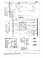
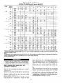
SCHEMATIC
MkXI_iJM WI_[
_IZE
2 AwG
I
_
_
III
I
USED wITH
A{¢ESSOffY
WIBL_
_UPPLY
w2
OPTIO_
O_LY
HEAI[N
OPIIO
GND
,t ....
I
gL K
MAX _lff[
r_O
_P
Y[L
POw[R
[OULP
FO_
5 KWl
<_, _ _,_,
,
_c_
BLI(
_
50JSO
_l
60_LI]
L_
_
_WWI9
_
-
_-T_-60
AMP
USED WI1H
ACC[SSO_I
%
_ OMP
50 JX030
_--fCONN[CT
S B
_BLK
FIIZ
i
tpELU_
B_sw_t
OPTION
ONLI
I
U_ED WIIH
[L{C]
H[AI
ItEAI[R
_pl IONS
51(W (04_
OBOI
90
ONLII
_LIJ
ME
2F_[_
F_R
j
IrM
AMP _ B
C_PI
9
_TLL--
0_ qu
Br
_L_
ZtO
MAI
WIRE
AMP [OP_
?_ '018
_ I/ I0_01
I KW
USEO Wllk_
ACC[ 5501_ I
I
50
AMP S B
_14!
60
AMp
160
_TRI
\_
S g
iWllO
_
OPTION QN[Y
US[D WI[H
m
HEAIEII OPILONS
15KW(030
0601
20KWIO_6
0601
2/0 MAX W RE
o B
_0 AMp S
-<TO
HT_
_
60
A_P
S B
50
A_P
•
HI
2 AMP
MANUAL YEL_
R[S[T
TRANI
Ill
BgN
-WI2
BR_
F----WII50RN_
F
S[[
----WI
L
HOT[ 15_
3 RID
__WI7
DEF_OST_
NED_
W18
BOARD
(DBI
r=:_L_ _[_l!0_00
PNK_
_EL--
]
_19
PNK_
B_I_ _*
CTD
B_U
0_N--
_10
B_N
_3
B_
T[S_
_
--_2_
B__3
B_
-W12
k
SUPPL 8Ikt
FIELDSEE
ACCESSSORI
W2
EL[_TRIC
flEAT
BRN--
•
C:
THERMOSTAT
NOT£12
--_69
HRI
VIO
--Wl20
& _ (10
KWI_2
7 BRN
I
"-,kS2'--'
6RA
HNI2
_21BRN
HRI23
m
_
3 115
& _ 120
_wlJ
I
121B_N
BRN--
K_I _W123
24V
ONI[
COMPOb_[III
ARRANG[M[IIT
rl[uo S_LIC[
S_¢TIOW
$[Ct_
--_¢t_i
WI_I_
A,_
_oaU_;Ank[H[_t X.rlCreAt_
_to
C_p_SOI
T,_[ oe_
et_<thT_l
CTit;ill
C_p_[_S_
OELA_
#Op
i _.l_
ggl
TS_
i
D[rrosl
BOAeO
ot
_DrUPL[
T_.I_
_
TI.I D_L_t_IL_t
TW[_T_T
.(_TI_
[ou,p
'k
50JS500005
i66_
Fig. 13--Wiring
Schematics
(208/230-1-60)
ROUTING CONTROL POWER WXRF_ (24-V)
low-voltage hole provided in unit into unit control power splice
Form a dsip-loop with the thermostat leads before routing them
into the unit. Route file thermostat leads through grommeted,
box (See Fig. 2 and 3). Connect thermostat leads to unit conlrol
power leads as shown in Fig. 17.
13
SCHEMATIC
208123@3-60
[0FM
L
rONL¢I
IDR
RED
YEL_
GR_
YEL_W26
GRN-YEL
GRN
YEL_
GRN
YZL
TRANI
Wll
BRN
_12
_RN
I0
BRN
II
BRN
RED
--WI6
GRN
_TT
--WII90RN_
B
see NOTe#5--_
Im
_[FROST_
-
BOAR_
IDB) _{_50_0
--
I
K13o
AUIO_
[51
--wI8
TEL
>Fr
LPS
_
_L_TBLU
i
ON
--WIT
_ro_?:BRNB_
WNT
RE_
W20
W22 BLK_W??
'
UppL
[_T
BRN--
_UPLH"_
1H2
_CCESSORI
k
L
W2
I
SUPPL HEAT
FI[LD
S[E
_
I
TH[RMOSIAT
NOTE#2
[LECIRIC
HEAI_
q
_7_
WH[
I
WI30
mWI31PN_
_133
I
VIO
GRk
HRI
? 3 & 4
(20 K_l_
I
UNIT
COWPONENT
ARRANGEMENT
_
)UTOOOe F_
SECTlOW
Frn
r_
rm
rl_ D _tlCE
_a_
_JUSTXBL_ N_
_OFWJ
_
_N_,_l_tO_
t_r
(I 3_
L
_
EN
UeOST
/
CTCL_
t_
--22/
L;O )134
Fig. 14--Wiring
Schematics
The unit transformer supplies 24-v power for complete system
including accessory electrical heater. An automatic-reset circuit
breaker (See Fig. 19) is provided in the 24-v circuit; see die caution
(208/230-3-60)
label on the transformer or Fig. 20. Transformer is factory wired
14
--,
_
AXIMIJ_ WIRE
SIZE
Z AWG
ii
EOUIP
WITH
ELECT
OpIlON
H/AT[_
SCHEMATIC
IE L
SUPP
Y
BLtJ--
GND
-- -IIII
HEAl
ONLY
OPIIONS
51015
USEO 'IIH& 20
MAI
, _T_
WI BLK--
IIIIL_oWER_w2
_W
USED
F_ELD
W]RL
lie
KW-i
'_
_
/
SEE
NOIE
15_
pLI-I
C001_5
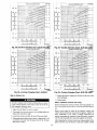
Fig. 15_Wiring
Schematics
for 230-v operation.If supply voltage is 208-v, rewire _ansfozTn_r
primary as described in Special Procedures for 208-v Operation
section,
(460-3-60)
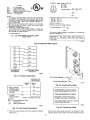
SPECIAL PRO_EDUP_S FOR 208-V OPERATION
1. Disconnect the yellow primary lead from the transformer. See
unit wiring label (See Fig. 13 and 14).
15
EXAMPLE: Supply voltage is 460-3-60.
A B c
AB = 452 v
FLA
-- Full Load Amps
LRA
-- Locked Rotor Amps
MCA
-- Minimum Circuit Amps
MOCP -- Maximum Overcurrent Protection
RLA
-- Rated Load Amps
CKT BKR -- Circuit Breaker
LEGEND
AC = 455 v
C@
II_il_
Average Voltage = 452 + 464 + 455
3
BC = 464 v
= 1371
3
= 457
NOTES:
1. In compliance with NEC (National Electrical Code) requirements
for multimotor and combination load equipment (refer to NEC
Articles 430 and 440), the overcurrent protective device for the
unit shall be Power Supply
fuse. Canadian units may be
fuse or circuit breaker.
2. Minimum wire size is based on 60 C copper wire. If other than
60 C wire is used, or if length exceeds wire length in table,
determine size from NEC.
3. Unbalanced 3-Phase Supply Voltage
Never operate a motor where a phase imbalance yn supply voltage is greater than 2%. Use the following formula to determine
the percentage of voltage imbalance.
Determine maximum deviation from average voltage.
(AB) 457 452=5v
(BC) 464 457=7v
(AC) 457 455=2v
Maximum deviation is 7 v.
Determine percent of voltage imbalance.
% Voltage Imbalance = 100 x
= 1.53%
This amount of phase imbalance
maximum allowable 2%.
% Voltage imbalance
= 100 x
7
457
max voltage deviation from average voltage
average voltage
is satisfactory as it is below the
IMPORTANT:
If the supply voltage phase imbalance
is]
more than 2%, contact your local electric utility company/
immediately.
I
C99024
Fig. 16_Electrical
L
Data Legend
"_BRN--
@
"J_ORN--
__
J_--_RED--
"J_GRN--
THERMOSTAT
AND SUBBASE
UNIT CONTROL POWER
SPLICE BOX
C99056
Fig. 17--Control
Connections
24 V Circuit Breaker
GROUND
LUG
N SLPICE BOX
C99070
GROUND
LEAD
Fig. 19_Control
SINGLE-PHASE
CONNECTIONS
TO DISCONNECT
PER NEC
L1
-
L2
- _-'_
3-PHASE
CONNECTIONS
L3
- _L-_BLU--
Wiring Plate
/L_BLK-TRANSFORMER
CONTAINS A MANUAL
RESET OVERCURRENT PROTECTOR
m
YEL-
NOTE:
IT WILL NOT AUTOMATICALLY
RESET
DISCONNECT POWER AND INSTALL
LOCKOUT TAG PRIOR TO SERVICING
Use copper wire onl
LEGEND
NEC - National Electrical Code
- - Field Wiring
_
Splice Connections
THIS COMPARTMENT MUST BE CLOSED
EXCEPT WHEN SERVICING
C99058
C99057
Fig. 20_Transformer
Fig. 18---Line Power Connections
2. Connect the yellow
labeled 200 v.
primary
lead to the transformer
terminal
Label
Indoor blower-motor speeds may need to be changed for 208-v
operation. Refer to indoor airflow and airflow adjustments section.
16
PRE-START-UP
Failure
to observe
serious
personal
I. Follow
the following
injury
goggles
when
safety
checking
could
or servicing
protective
refrigerant
system.
or provide
compressor
terminal
any electric
cover
erant
6.
leak is suspected
attempt
to repair
system
Do
not
is under
use
around
soldered
torch
compressor
any
under
wear
1/8" (3 175mm) MAX BETWEEN
MOTOR AND FAN HUB
terminals.
while
component.
pressure.
protective
C99009
Fig. 21--Fan
System
and
Using
unsweat
Use the Start-Up
proceed
as
remaining
tubing
cutter
and
l.
tubing
supplied
to inspect
stubs
when neces-
to torch
at the end of this book
and
prepare
the
unit
and
for initial
2. Read
access
and follow
CAUTION,
shipped
3. Make
instructions
and
on all DANGER,
INFORMATION
labels
a. Inspect
lines,
loose
unit
to,
leak.
and handling
etc.
tubing
connections
Leak-test
oil generally
all
refrigerant
leak detector,
erant leak is detected,
Leaks section.
all field
d. Ensure
wires
sheetmetal
e. Inspect
touch
b. Make
sure
with water
(See
remove
unit
Schrader
using
the
practices.
lie system
using an approved
R-22
refrigerant,
or accurate
has been
method.
required
operating
when
the outdoor
using
scale.
Refer
to 500
volumetric-
to unit rating
to add extra
of filter drier.
plate
refrigerant
to
Adjustments
starting
when
Allow
for Refrigerant
connections.
during
tubing
shipping
Be sure
procedures
given
the unit. Do not operate
temperature
between
the
40 ° F (unless
Do not rapid-cycle
"'on"
Pre-Start-Up
any safety devices
the unit in Cooling
is below
kit is installedl.
5 minute
in
the unit. Do not jumper
cycles
CHECKING
COOLING
CONTROL
OPERATION
mode
accessory
the compressor.
to prevent
compressor
operation
as follows:
Observe
and handling,
conditions:
blade is correctly
positioned
drainage.
proper
and trap
spring
holddown
mounted.
and
switch
in AUTO
is placed
position.
3. Place
on the suction
loose parts have
down
ports,
one
shuts
switch
switch
starts
when FAN
down
within
position.
switch
is placed
60 sec.
when
FAN
position.
in COOL
Set control
position
and FAN switch
below room temperature.
cycle shuts down when control
switch
in OFF
in HEAT
position.
setting
Set
in
Observe
is satisfied.
control
above
room temperature.
Observe that compressor,
outdoor fan, and
indoor blower motors start. Observe that heating cycle shuts
or
when control
setting
4. When using an automatic
boll SYSTEM
and FAN
bolts.
has 2 Schrader-type
system
control
SYSTEM
motor
in ON position
AUTO
are filled
Do not loosen
thermostat
that blower
that cooling
to ensure
are internally
room
2. Place SYSTEM
in
Fig. 21).
pan
AND HEATING
Start and check the unit for proper
or sharp
a fin comb.
drain
system
with
cylinder
before
low-ambient
If a refrig-
and tight.
refrigerant
fins will
fitting located
accepted
filter drier whenever
for leaks
2--Start-Up
section
and on
connections
Check
that condensate
compressor
system
system
a
Step
a refrigerant
solution.
c. Make sure that all tools and miscellaneous
been removed.
5. Compressors
leak following
to relieve
refrigerant.
unit
1. Place
sure that outdoor-fan
fan orifice
remaining
the unit as follows:
ports
damage.
coil fins. If damaged
the following
a. Make
see following
not
straighten
and reclaim
charging
edges.
carefully
4. Verify
tubing
or liquid-soap
are completed
do
low-pressure
5. Charge
Complete
indicates
and factory-wiring
that connections
leaks and charge
and
system
or
such as broken
wires,
electronic
c. Inspect
damages
disconnected
Detecting
high-
for required
charge.
Be sure
compensate
for internal volume
for oil at all refrigerant
base.
parts,
both
Leaks
refrigerant
and evacuate
refrigerant
if no additional
leaks are found.
inspections:
for shipping
b. Inspect
6. Each
WARNING,
attached
at the end of this book.
4. Reclaim
microns
with, unit.
the following
and repair refrigerant
Use
3. Check
panel.
supplied
for Refrigerant
NOTE:
Install a bi-flow
opened for repair.
start-up:
1. Remove
1--Check
2. Repair
flame.
Checklist
as follows:
pressure
when exposed
Checklist
follows
the Start-Up
Step
from unit.
sary. Oil can ignite
Blade Clearance
START-UP
goggles
Locate
boll high- and low-pressure
ports.
c. Cut component
connecting tubing will
MOTOR SHAFT
refrig-
a. Shut off electrical power to unit and install lockout tag.
b. Relieve and reclaim all refrigerant
from system using
d. Carefully
and tight or lhe
occur.
before
box if
proceed
component
could
and
as follows:
remove
caps are in place
leakage
until all electri-
connection
to remove
the plastic
or refrigerant
pressure.
contains oil and refrigerant
To remove
a component,
proceed
possibility
power to
is in place
and recover
all refrigerant
from system
or disturbing
anything
inside terminal
refrigerant
5. Never
in
and wear
3. Do not remove compressor
terminal cover
cal sources are disconnected
and tagged.
4. Relieve
touching
result
the field. Ensure
practices
compressor
unit unless
secured.
warnings
discharge line. Be
7. High flow valves are located on the compressor
hot gas and
suction tubes. These valves can not be accessed for service in
or death:
recognized
2. Do not operate
Schrader fitting located on the compressor
sure that caps ,)l] the ports are tight.
low-side
serve
line, and one high-side
control
17
that unit operates
is satisfied.
changeover
room thermostat,
place
switches
in AUTO positions.
Ob-
in Cooling
is set to "'call for Cooling"
mode
(below
when
room
temperature
temperature),
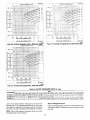
OUTDOOR
COIL
INDOOR
COIL
tcs
LI ¸
Me_n_
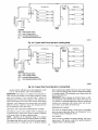
LEGEND
HPS - High Pressure Switch
LCS - Loss of Charge Switch
_
Accuratel = Metering Device
]
Arrow indicates direction of flow
C00095
Fig. 22--Typical
Heat Pump Operation, Heating Mode
OUTDOOR
INDOOR
COqL
COIL
LC$
Bypass
Position
LEGEND
HPS - High Pressure Switch
LCS - Loss of Charge Switch
_
Accuratef' Metedng Device
]
Arrow indicates direction of flow
C00096
Fig. 23--Typical
and unit operates
is set to "call
IMPORTANT:
ented.
in Heating
Three-phase.
scroll
Unit must be checked
power
lead
mode
for Heating "_(above
orientation.
proper
corrected
label is attached
control
are direction
compressor
within
to the outside
level is suspect
temperature).
compressors
to ensure
If not
when temperature
room
Heat Pump Operation, Cooling Mode
to nameplate
ori-
physical
3-phase
5 minute,
in Heating
amount.
(This
When
cated
backwards,
difference
condition exists somewhere
ficient airflow across either
may be dramatically
CHECKING
AND
The refrigerant
is tested
NOTE:
system
and factory
of 15 minutes
lower
very minimal.
before
Adjustment
than normal.
ADJUSTING
sealed.
Allow
checking
of the
unless the unit is suspected
with R-22 refrigerant
system
or adjusting
refrigerant
of not having
CHARGE
to operate
The amount
and
and/or
a minimum
is not
the proper
from the
the refrigerant
charge,
factory
must
adjustment
charge
is indicated,
in the cooling system,
coil or both coils.
an indialways
be
an abnormal
such as insuf-
of refrigerant
Manual,
data
charge
table.
Refrigerants
is listed on the unit nameplate
Refer
to the Refrigeration
Service
Section.
NO CHARGE
required
Check for leak. Use standard evacuating techniques. After evacuating system to 500 microns, weigh in the specified amount of
refrigerant (refer to system data plate).
R-22 charge.
The charging
label and the tables shown refer to system
tures and pressures
in cooling mode only. A refrigerant
and charge
may be obtained
CHARGE
the physical
Techniques
charge.
charge
to the specified
If a substantial
REFRIGERANT
REFRIGERANT
is fully charged
adjustment
evaluating
internal protector will shut off the compressor.
The 3-phase power
leads to the unit must be reversed to correct rotation. When turning
scroll compressors
emit elevated
noise levels, and the
between
compressor
suction and discharge
pressures
information
access door. If charge
all refrigerant
data table also.)
IMPORTANT:
the
of the service
mode, reclaim
temperacharging
18
Balance Point Worksheet
7O
Based
on Indoor
Entering
Air of 70 F and Rated
CFM
6O
B50
co
:to°
8_
ou
--'_--024
40
--11--030
_Q-
--'_-- 036
_
---X---042
C
i_
---,_<--048
30
--O_-060
m_
__ 2o
lO
o
-lO
10
17
20
30
40
47
50
60
Outdoor Air Temp (Deg F)
C00093
Fig. 24--50JX
LOW
CHARGE
Use Cooling
Balance Point Worksheet
COOLING
Char_ng
NOTE:
Charts
(Fig. 26 38). Vary
refrigerant
Be sure that all supply-and
from obstructions,
until
and adjusted
the conditions
of the chart are met. Note that charging
charts are
different from type normally
used. Charts are based on chafing
Airflow can be changed
blower motor.
the units to correct
superheat
Unit 50JS and 50JX
Accurate
pressure
gage
required.
Connect
the
for the various
and
operating
temperature
pressure
gage
sensing
to the
conditions.
devices
service
port
are
50JX
on the
030
suction line. Mount the temperature
sensing device on the suction
line and insulate it so that the outdoor ambient does not affect the
reading.
Indoor air CFM
range of the unit.
TO USE COOLING
Take
the
pressure
temperature
NOTE:
If the
refrigerant
INDOOR
the
normal
two-speed
AIRFLOW
the lead connection
motors (except
for low speed
for medium
wired
are open, free
speed.
of the
sizes 50JS 018 and
operation.
Unit
50JS
Unit 50JX
018
has a
for low speed.
Motors:
The
motor
leads
are color-coded
as
Black = high speed
temperature
and
to determine
read
the
what
the suction
Blue = medium
suction
To change
causing
to Check
the
inaccurate
for Refrigerant
AND AIRFLOW
readings
Leaks
speed
Red = low speed
be.
problem
speed
wired
wired
motor
For 208/230-v
follows:
operating
CHARTS
to the chart
leak, refer
is factory
by changing
three
are factory
grilles
3-SPEED
ambient
Refer
should
be within
CHARGING
outdoor
gage.
must
030)
return-air
properly.
the speed
motor speed
is a
is attached
section.
of the indoor fan motor (IFM),
leg lead from the Time Delay Relay
to TDR-3
for single-phase
and 3-phase
remove
(TDR).
the fan
This wire
units. To change
the speed, remove and replace with lead for desired blower motor
speed, hlsulate
the removed
lead to avoid contact with chassis
ADJUSTMENTS
parts.
For 460-v
follows:
For heating
and cooling
is 350 to 450
cfm
operation,
for each
the recommended
12.000
Btuh
of rated
airflow
to maintain
these airflows
could result in damage
Motors
The
motor
leads
are
color
coded
as
3-SPEED
cooling
Black = high
capacity.
For units with optional electric heat, the airflow
must not be reduced below the levels stated in Tables 3 and
4. Failure
the unit.
GE
Violet = jumper
Orange = medium
Red = low
to
To change
the speed
of the indoor
fan motor (IFM),
remove
fan
Tables 7 and 8 shows both heating and cooling airflows at various
external static pressures.
Refer to these tables to determine
the
motor speed lead from the Time Delay Relay (TDR) and replace
with the lead for the desired blower motor speed. The motor speed
airflow
lead is attached
for the system
being
nsta ed
19
to terminal
TDR-3.
For low and medium
speeds,
Balance Point Worksheet
7O
Based
on Indoor
Entering
Air of 70 F and Rated CFM
6O
m
50
z8
F-_
m&
8_
i_
30
__ 20
10
-lO
lO
17
20
Outdoor
30
47
40
50
60
Air Temp (Deg F)
C00094
Fig. 25---50JS Balance Point Worksheet
black must be connected
end to avoid
contact
to the jumper
with
chassis
wire. Insulate
parts.
To select
removed
lead
high speed
on
460 v GE motors, separate
the black female quick connect (QC)
from the jumper lead male quick connect (QC) and connect the
Failure to follow
or death:
black lead to the BR. Insulate
1. Turn off electrical
chassis
the jumper
to avoid contact
with any
before
parts.
To
ensure
possibility
continuing
high
of premature
must be performed
performance,
equipment
and
failure,
on this equipment.
to minimize
periodic
be inspected
at least once each year by a qualified
To troubleshoot
unit, refer to Table I I.
NOTE
about
TO EQUIPMENT
the availability
OWNER:
of a maintenance
Consult
your
local
caution
3. Never place anything
with, the unit.
unit should
service
ment
requires
to properly
certain
perform
expertise,
equipment,
panels
personal
tag
and parts. As
injury
can result
combustible
either
om or in contact
dealer
maintenance
made
when
mechanical
skills,
tools
reconnecting
operation.
Label
wires
may cause
improper
all wires prior to disconnect-
ing when servicing.
on this equipand
The minimum
follows:
equipment.
If you do not possess these, do not attempt to
perform any maintenance
on this equipment,
other than those
1. Inspect
procedures
recommended
in the User's Manual. FAILURE
TO HEED THIS WARNING
COULD
RESULT
IN SERI
OUS INJURY OR DEATH AND POSSIBLE
DAMAGE TO
THIS
when removing
lockout
on this unit.
contract.
and dangerous
ability
or service
injury
person.
Errors
The
in serious
from sharp edges.
maintenance
This heat pump
any maintenance
with any mechanical
the
could result
power to the unit and install
performing
2. Use extreme
MAINTENANCE
these warnings
maintenance
air
filterlsl
requirements
each
month.
drain
pan.
for this equipment
are as
Clean
when
or
replace
necessary.
EQUIPMENT.
2. Inspect
indoor
coil,
cooling
season
for cleanliness.
3. Inspect
blower
season.
4. Check
proper
motor and wheel
Clean
and condensate
Clean
drain
each
when necessary.
for cleanliness
each cooling
when necessary.
electrical
operation
connections
for tightness
and controls for
each cooling season.
Service when neces-
sary.
5. Ensure
sheet
20
wires
metal
axe not contacting
edges.
refrigerant
tubing
or sharp
Table 7--Wet Coil Air Delivery
Unit 50JS 018-060 (Deduct 10 percent for 208-V)*
MOTOR
SPEED
UNIT
0.0
Low
018
Med
Low
Med
Low
Med
Cfm
821
696
575
283
274
267
848
707
555
Watts
237
214
191
Cfm
971
821
696
WaRs
368
366
365
Cfm
957
872
785
WaRs
295
292
289
0.8
0.9
Low
Med
High
Low
Med
802
Low
Med
414
891
735
928
882
388
383
377
372
366
Cfm
1203
1120
1062
1004
930
838
469
458
449
442
1141
1027
924
828
361
WaRs
592
581
567
552
538
525
512
499
Cfm
1499
1421
1351
1281
1207
1125
1034
936
WaRs
660
636
617
603
592
581
566
Cfm
1475
1371
1274
1186
1105
1024
928
776
1452
761
1356
744
1254
725
1145
706
1030
WaRs
606
596
586
575
563
550
537
1066
Cfm
1464
1399
1341
1282
1218
1146
WaRs
680
665
649
635
622
611
600
590
Cfm
1608
1535
1461
1387
1316
1247
1180
1111
WaRs
Cfm
768
1656
755
1576
742
1508
730
1447
718
707
696
684
671
1390
1331
1268
1198
1119
WaRs
741
724
709
690
664
631
594
562
543
552
Cfm
1994
1937
1869
1797
1722
1645
1566
1480
1384
1269
WaRs
773
744
715
687
662
640
625
Cfm
1957
1867
1787
1719
1653
1575
1463
799
782
773
756
704
1914
1842
1774
1686
1538
WaRs
742
723
698
666
629
591
559
540
Cfm
2197
2141
2103
2057
1988
1894
1783
1674
Watts
838
822
803
780
752
721
689
661
639
632
Cfm
2485
2406
2269
2127
2012
1937
1894
1855
1770
1571
934
2483
913
2391
891
2283
866
837
806
776
780
735
2170
2061
1960
1868
1780
1687
Watts
Cfm
High
688
425
Cfm
WaRs
Cfm
High
• Air delivery values are based on operating voltage of 230-v or 460-v, wet coil, without fiRer or electdc heater. Deduct tilter and electric heater pressure
static pressure available for ducting.
NOTES:
1. Do not operate the unit at a cooling airflow that is less than 350 cfm for each 12,000 Btuh of rated cooling capacity.
this point.
2. Dashes indicate per{ions of table that are beyond the blower motor capacity or are not recommended
3. Deduct 10 percent for 208-v.
Step
1--Air
IMPORTA,
Step 2--Indoor
Filter
NT: Never
in the return-air
operate the unit without
duct system.
Always
replace
same dimensional
size and type as originally
1 and 2 for recommended
filter sizes.)
Inspect
air
filter(s)
(throwaway-type)
each cooling season
dust and lint.
1,0
360
WaRs
Watts
Cfm
High
6O
170
WaRs
Cfm
High
48
191
Watts
Cfm
High
42
214
Cfm
Low
36
WaRs
WaRs
Cfm
High
30
EXTERNAL STATIC PRESSURE (IN. WG)
0.3
0.4
0.5
0.6
0.7
0.2
WaRs
Med
024
0.1
at
or clean
least
once
each
(cleanable-type)
or whenever
a suitable
air filter
the filter
with the
installed
month
replace
clogged
drops to obtain
coil frosting may occur at airflows below
blower and motor
For longer life, operating economy, and continuing efficiency.
clean accumulated dirt and grease from the blower wheel and
motor annually.
at least twice during
the filter becomes
910
NOTE: All motors _e prelubricated. Do not attempt to lubricate
these motors.
(See Tables
and
Evaporator
689
with
21
Table 8_Wet Coil Air Delivery
Unit 50JX 024-060 (Deduct 10 percent for 208-V)*
MOTOR
SPEED
UNIT
Low
024
Med
Low
Med
Low
Med
Low
Med
275
273
271
270
Cfm
923
844
754
669
(IN. WG)
0.7
Med
Low
Med
High
0.9
359
353
350
347
341
Cfm
941
876
814
737
622
447
439
431
423
968
869
765
659
WaRs
276
276
272
781
Cfm
963
929
WaRs
375
377
371
362
354
350
Cfm
1202
1170
1079
976
884
807
469
449
435
428
1174
988
828
718
WaRs
462
451
431
411
394
381
Cfm
1374
1290
1205
1116
1020
916
WaKs
523
506
490
471
449
426
Cfm
1500
1408
1301
1190
1082
977
645
1474
628
1369
610
1267
595
584
575
1169
1069
962
1.0
Watts
620
600
586
574
562
548
530
510
487
462
439
Cfm
Watts
1662
1621
1581
1540
1496
1447
1392
1331
1263
1186
1103
686
661
634
6O6
577
547
517
1722
1662
1594
1515
757
1427
730
1330
704
1227
682
1669
1577
1486
1402
Watts
620
600
586
574
562
548
530
487
Cfm
1662
1621
1581
1540
1496
1447
1392
1331
Watts
763
747
729
709
686
661
634
606
577
547
517
Cfm
1917
1868
1822
1774
1722
1662
1594
1515
1427
1330
1227
852
1982
832
809
784
757
730
704
682
1914
1839
1757
1669
1577
1486
1402
watts
Cfm
High
0.8
WaRs
Watts
Cfm
Low
60
WaRs
Cfm
High
48
EXTERNAL STATIC PRESSURE
0.3
0.4
0.5
0.6
Watts
Cfm
High
42
0.2
WaRs
Cfm
High
36
0.1
WaRs
Cfm
High
30
0,0
Wa_s
597
592
578
526
460
452
445
Cfm
2265
2190
2101
2033
1974
1869
1614
1263
Watts
754
730
707
687
671
658
646
630
603
558
486
Cfm
2383
2282
2202
2134
2070
2005
1935
1858
1771
1667
1576
Watts
Cfm
901
2480
876
2383
856
2301
836
2233
813
785
755
723
696
681
687
2175
2122
2066
1998
1910
1788
1619
• Air delivery values are based on operating voltage of 230-v or 460-v, wet coil, without fitter or electric heater. Deduct tilter and electric heater pressure drops to obtain
static pressure available for ductin9.
NOTES:
1. Do not operate the unit at a cooling airflow that is less than 350 cfm for each 12,000 Btuh of rated cooling capacity, Evaporator coil frosting may occur at airflows below
this point.
2. Dashes indicate portions of table that are beyond the blower motor capacity or are not recommended.
3. Deduct 10 percent for 208-v.
attachment.
r_ k','l_ ;1: I1: [,]
Disconnect
cleaning
1o adhere
and
tag
electrical
and lubricating
power
the blower
to this warning
could
to
motor
cause
the condenser
pan at lea-st once
conditions
coil, evaporator
each
heating
before
and wheel.
Failure
injury
COIL,
through
Straighten
bent
clean
coils
fins with
or death.
with
with oil or
solution.
using a garden hose. Be careful
insulation,
wiring, or air filter(s).
coil fins from inside to outside
not to
For best
the unit.
On units with an outer and inner condenser
coil, be sure to clean
between the coils. Be sure to flush all dirt ,and debris from the unit
AND
and condensate
season
when dry: therefore,
drain
or sooner
Inspect
if
inspect
If coated
cleaner,
using
and clean
soft
matter
clear water.
pan and condensate
drain
brush
22
line when inspecting
drain by removing
from the pan. Flush the pan and drain trough
Do not splnxh water
or air filter(s).
with dirt or lint,
the
the drain
the coils. Clean the drain pan and condensate
coil.
a vacuum
the fins. If coated
a mild detergent-and-water
base.
coil,
and cooling
a fin comb.
not to bend
the coils with
splash water on motors,
results, spray condenser
or after each cooling season. Remove
all
weeds and shrubs, that interfere with the
the condenser
Be careful
clean
Rinse coils with clear water,
foreign
the coils either before
obstructions,
including
the
unit
require.
The coils are easily cleaned
airflow
the
serious
Step 3_UTDOOR
COIL, INDOOR
CONDENSATE
DRAIN PAN
Inspect
grease,
If the drain
'*plumbers snake"
or similar
drain port above
the drain
on the insulation,
trough
is restricted,
motor,
clear
all
with
wiring,
it with
probe device. Ensure that the auxiliary
trough
is also clear.
a
(018) 60HZ CHARGING
6891
CHART
(024) 60HZ CHARGING
CHART
52
100
46
41
;Os5.
48:
414:
95
35
85
29
75
24
65
18
55
13
45
7
z
O
345 (n 50 "
2071
20.0 3o.o .o.o so.o 6oo
SUCTION
17
LINE TEMPERATURE
I
4
10
LINE TEMPERATURE
-1
SUCTION
_o.o
20.0
30.0
40,0
500
60.0
SUCTION LtNETEMPERATURE
°F
I
"I
-1
4
10
16
SUCTION LINE TEMPERATURE
°(_)
(°F)
16
(°C)
I
21
I
27
50JS500087
I
-7
!
L
700
80.0
I
21
•
27
50JS500088
50JS 024
(036) 60HZ CHARGING
90 _
III
_
CHART
""-',_
ZTO _
-_
J
-If
i _ 414
io
_50
I
20.0
[ .........
20.0
r ____ SLICTION
-7
L[NE TEMPERATURE
÷1
4
10
(_F)
16
I
21
r
-7
27
50JS500089
C00028
Fig. 28.--Cooling
Step 4--Outdoor
30.0
40.0
50.0
60.0
SUCTION LiNE TEMPERATURE
{°F)
I
I
I
I
-1
4
10
16
SUCTION LINE TEMPERATURE °C_
Charging Chart, 5OJS030
Fig. 29--Cooling
fan
5. Ensure
i
I
27
5=0_J=SSOOOgp=J
I
21
....
engages
the flat area on the motor
shaft
tightening.
6. Replace
Step
800
Charging Chart, 50JS 036 UnCi°t=
_29
s
that setscrew
when
70.0
grille.
5_Electrical
controls
and wiring
Inspect and check the electrical controls and wiring annually. Be
sure to turn off the electrical power to the unit and install lockout
tag.
1. Inspect
the fan blades
for cracks
or bends.
Remove
2. If fan needs to be removed,
intake
3. Loosen
grille
and remove
the setscrew
4. When replacing
remove
screws holding
outdoor air
grille.
and slide the fan off the motor
fan blade,
in. (See Fig. 21) away
shaft will be visible).
position
shaft.
panel
Check
screw
connections.
noticed,
end (1/8 in. of motor
to locate
all electrical
disassemble
all the
connections
If any
smoky
the connection,
wire end and reassemble
blade so that the hub is 1/8
from the motor
access
wiring.
electrical
or
clean
the connection
controls
for tightness.
burned
Tighten
connections
all the parts, restrip
properly
and
all
are
the
and securely.
After inspecting
the electrical controls and wiring, replace all the
panels. Start the unit, and observe at least one complete cooling
23
(042) 60HZ CHARGING
20.0
3o.o
40.0
SUCTION
LINE TEMPERATURE
(°E_
-1
SUCTION
4
10
LINE TEMPERATURE
16
I'C).
-7
so.o
)Lr'CObqTEt4;
F
CHART
60.0
700
s0.0
200
6891 100i
_I
tl
L
400
50.0
60 0
70.0
52
115
46
105
95
41
35
85
29
75
24
65
18
55
13
45
7
800
=
21
27
50JS500091
-7
[
J
-1
SUCTION
SUCTION
Fig. 31--Cooling
50JS
(060) 60HZ CHARGING
30 0
125
4
10
LiNE TEMPERAT_
LINE TEMPERATURE
16
(°_
2t
27
50JS500092 j
Charging Chart, 50JS
048
Unl_0031
CHART
,
i[
i:_
J_
_r
i
i i k.,,,u,_ !
20.0
30.0
SUCTION
-7
40.0
50.0
60.0
LINE TEMPERATURE
(°F)
-1
4
SUCTION
Fig. 32_ooling
10
16
LINE TEMPERATURE
]
i
70.0
80.0
/
21
27
(°C}
....
Charging Chart, 50JS 060 unCi°t=
_ 32
Table 9_FILTER
FILTER SIZE
20X20X1
CFM
500
600
700
800
900
1000
1100
1200
0.05
0.07
0.08
0.10
0.12
0.13
0.14
0.15
0.09
0.10
0.11
20X24X1
24X30X1
cycle to ensure
proper
operating
or if a suspected
cycle,
each electrical
operation.
component
Refer
determining
label
to the Sequence
proper
control
If discrepancies
malfunction
with the proper
tion. Refer to the unit wiring
NOTE:
PRESSURE DROP (In. wg)
of Operation
1400
1500
0.13
0.14
0.15
0.16
0.07
0.08
0.09
0.10
are observed
has occurred,
electrical
when making
1300
these
section
Step
in
check
Inspect
instrumenta-
as an aid in
operation.
24
1700
1800
1900
2000
2100
0.11
0.12
0.13
0.14
0.15
0.16
6---Refrigerant
all refrigerant
accumulation
erant leak.
checkouts.
1600
annually.
2200
0.17
2300
0.18
circuit
tubing
connections
Detecting
and the unit base for oil
oil generally
indicates
a refrig-
Table 10_ELECTRIC
HEAT PRESSURE DROP TABLE
Small Cabinet
CFM
STATIC
500
600
700
800
900
1000
1100
1200
1300
1400
1500
1600
5 kw
0.00
0.00
0.00
0.00
0.00
0.00
0.00
0.00
0.02
0.04
0.06
0.07
10 kw
0.00
0,00
0.00
0.00
0.00
0.02
0.04
0.06
0.07
0.09
0.10
0.11
15 kw
0.00
0.00
0.00
0.02
0.04
0.06
0.08
0.10
0.12
0.14
0.16
0.18
20 kw
0.00
0.00
0.02
0.04
0.06
0.08
0.09
0.11
0.13
0.15
0.17
0.19
Large
Cabinet
STATIC
1100
1200
1300
1400
1500
1600
1700
CFM
1800
1900
2000
2100
2200
2300
2400
2500
5 kw
0.00
0.00
0.00
0.01
0.02
0.03
0.04
0.05
0.06
0.07
0.08
0.09
0.10
0.11
0.12
10 kw
0.00
0.00
0.01
0.02
0.03
0.04
0.05
0.06
0.07
0.08
0.09
0.10
0.11
0.12
0.13
15 kw
0.00
0.02
0.03
0.04
0.05
0.06
0.07
0.08
0.09
0.10
0.11
0.12
0.13
0.14
0.15
20 kw
0.02
0.03
0.04
0.05
0.06
0.07
0.08
0.09
0.10
0.11
0.12
0.13
0.14
0.15
0.16
sec.,
fan relay
is energized.
delay is initiated.
relay
is de-energized
during
When
thermostat
is satisfied,
an off
When fixed delay of 60_+ 5 sec. is completed,
this delay,
and fan motor stops. If wall thermostat
TDR
is reset and fan relay
remains
fan
closes
energized.
TDR is a 24-v device that operates within a range of 15-v to 30-v
and draws about 0.5 amps. If the blower runs continuously
instead
If oil is detected
or if low performance
refrigerant
using
tubing
solution.
an electronic
If a refrigerant
Refrigerant
Leaks
If no refrigerant
leak
is suspected,
leak detector,
is detected,
leak-test
of cycling
all
probably
or liquid-soap
refer
to Check
Step
for
section.
12--Loss
and Adjusting
Step 7--Indoor
airflow
Refrigerant
switch contains
psig and closes
is suspected,
Charge
section.
NOTE:
indoor
airflow
performance
supply-
does
not require
is suspected.
and retunz-air
If a problem
grilles
is clean.
Airflow
airflow.
Adjustments
Airflow
Step 8--Metering
unless
When
improper
e.vists, be sure
are open and free from
and that tbe air filter
and
checking
necessary,
section
refer
to check
that all
to Indoor
the
system
Step 9---Liquid
(to protect
wire mesh and are located
metering
metering
drives)
located
for service
inside
the caps.
in the field.
Time-Delay
thermostat
is
There
is a liquid
going
into outdoor
hot gas and
these valves
valves
can
not
caps
are in
leakage
could
occur.
at 7
to refrigeration
to remove
this device
certain
for
that a problem
remove
and recover
read 0 psi.
Never
all system
open
system
with dry nitrogen.
defrost
header
thermostat
with
a brass distributor
and feeder
coil. At the end of 1 of the feeder
tube
tubes, there
thermostat
and on most
Thermostat
signals
heat pump
that conditions
are fight for
range
is closed
at 30 ° +/- 3°F
NOTE:
The defrost thermostat
must be located on the liquid side
of the outdoor coil on the bottom circuit and as close to the coil as
possible.
(TDR)
keeps
indoor
is a solid state
blower
This
of wail thermostat
gages
temperature.
Normal temperature
and open at 80 ° +/- 5°F.
be
the plastic
attached
opens
defrost or that conditions
have changed to terminate
defrost. It is
a thermally actuated
switch clamped to outdoor coil to sense its
relay
delay
residual
cooling
in coil after
improving efficiency
of system.
on closure
Ensure
of refrigerant
Relay
satisfied.
These
be removed,
vacuum
13--Check
are
you are reasonably
pressure
Step 14--Defrost
Valves
Step 11 --Time-delay
delay timer which
breaking
Defrost
Flow
place and tight or the possibility
The
without
switches
liquid line. This
This switch
is necessary.
that there is only 1 stub tube used with liquid header,
units it is the bottom circuit.
are made of
in the liquid lines on the inlet side of the
High flow valves are located
on the compressor
suction tubes. Large black plastic caps distinguish
with O-rings
so that
is
switch
it is not advisable
unless
the TDR
is a 3/8-in. OD stub tube approximately
3 in. long (See Fig, 40).
The defrost thermostat
should be located on this stub tube. Note
devices.
Step 10_High
accessed
in
line strainers
liquid line strainers
these
If switch must
charge
Step
device
Refrigerant
metering devices are fixed orifices and are located
the inlet header to the indoor and outdoor coils.
The
exists.
is set on AUTO,
be replaced.
switch is located on the outdoor
under pressure,
troubleshooting
obstruction._,
switch
a Schrader core depressor.
at 22 psig. No adjustment
Because
system
the fan
and must
of charge
The loss of charge
leaks are found and low performance
refer to Checking
The
off when
defective
operating
enables
compression
The sequence
control,
TROUBLESHOOTING
recycle
Refer
for 60 sec. after
blower
I I ) for troubleshooting
to remove
and Heating
Use the Start-Up
followed.
of 1
25
Troubleshooting
Chart
(Table
information.
START-UP
shutdown,
thereby
of operation
is that
and at end of a fixed on delay
to the Cooling
Checklist
CHECKLIST
to ensure proper start-up
procedures
are
(024_eO h_ Q._p_e_G
O_**RT
;too
nE_
i
I
I
J
200
:_0_
i
,7
q
I
400
SO0
SUCTK_NL_E rEe,_- R_JF_
e00
_=G
700
S00
i
2t
i
27
F)
4
10
16
SL,_T_e_ Ln,_ TEMPERATURE ICEG ¢_
_1XS00219
soJx
_J
,,i
'' 11 11 I
,_......
i i i _
;
i_
i
i
,i
,1/
; _._1._=
i _ _ =
I!11111= ' ....
2Oo
i
_oo
i
4oo
S_T_3N
i
soo
eoo
TEM_ER_t URE (DEG _1
i
p
I0
S_Ct K_N LI_ T_MPERA_JP_ _G
C_
L_
_o
i
SO_SC_2
Fia. 36.--Coolina
"i
i
r
! i
ii
i i
i i
i
]
clllkl;iLL
.........
i i_
_,
=
,-
Charaing_Chart,_5OJX .042 UnCi'_t=
_°34
s
_c
'_
lOOO
ii1_1
_o
i,iiil_llk
,,,,,,,I,,_,,,r1_
IIIl_lllI,EIIly_l_llflllllll
f
IIIllll_l,I
II_lllll=,L
lllllll_llL
,,,,,,,,ILL
,,,,,,111_
i1,1111=1_
,,I,,,,11_1
i1,111111_
i1_1111_1==
ilJl_llll_l
,,,,,,_11_1
,_I_=LIIII
,llllrll,=
_,_,,,_,,,,,
I
_
I1_.-_1111
_1111111_
I_lllrlll
,,,,,,i,,
,11111
iiii1=
i=1111
IJlIIL
i:1111
I_IIIL
IJlIIP
i_lllr
lll] llll
2OO
:mO
i_lJ_
7oo
z
,,. [
_o
_o
iiiiil
4OO
SUC'r_I
_00
L_
EM_P.='t_REI
_0
(D_GI _3
7OO
i
eoo
I7
i
_x_
Fig. 37---Cooling
_.o
i
Charging Chart, 50JX 048 Un_t__
Fig. 38--Cooling
'>6
Charging Chart, 50JX 060 Un=_s3_
_FEEDERTUBE
DEFROST
THERMOSTAT
Fig. 40_Defrost
Fig. 39_Refrigerant
Circuit
C99097
2?
Thermostat
C99092
Table 11_ooling
and Heating Troubleshooting
Chart
REMEDY
CAUSE
SYMPTOM
Power Failure
Compressor and outdoor
fan will not start
Call power company
Fuse b_own or circuit breaker tnpped
Replace fuse or reset circuit breaker
Defective thermostat, contractor,
control relay or defrost board
Replace component
insufficient
transformer,
Determine
line vofiage
incorrect or faulty widng
Thermostat
Lower thermostat
temperature
setting too high
Faulty widng or loose connections
circuit
in compressor
Determine cause
Replace compressor
Defective run capacitor, overload, or PTC
)ositive temperature coefficient) thermistor
Determine
cause and replace
Determine
cause and replace
One leg of 3-phase
Scroll compressor is rotating in the wrong
direction
Defective compressor
Replace
Insufficient
Determine
cause
and correct
Determine
cause
and correct
line voltage
Defective run/start capacitor,
relay
Defective thermostat
ovedoad
or start
Restriction
Locate restriction
(Continued
suction
pressure
system,
shown
and
on nameplate
cause
system
cause and correct
and remove
Replace filter
Decrease
for load
load or increase
unit size
Reset thermostat
set too low
Locate leak, repair, and recharge
charge
Leaking valves in compressor
Replace compressor
Frosted coil with incorrect
Check defrost time settings
Reset as necessary
Check defrost temperature switch
Replace as necessary
defrost operation
Air in system
Recover refdgeraet,
and recharge
Outdoor coil dirty or restdcted
Clean coil or remove restdction
Oirty air filter
Dirty indoor or outdoor coil
Replace filter
Clean coil
Refrigerant
Recover excess refrigerant
overcharged
evacuate system,
Recover refrigerant, evacuate system,
and recharge
Air in system
or recirculafing
Determine
cause and correct
Indoor or outdoor air restricted or air short-cycling
Determine cause and correct
Low refrigerant charge
Check for leaks, repair and recharge
Compressor
Replace compressor
Restriction
the
Determine cause and replace
Replace
Determine
in refrigerant
evacuate
determine
Damaged reversing valve
(Heat) Indoor air restdcted
Excessive
and
by reversing
unit
Replace thermostat
operates continuously
low
to the
to capacities
Low refrigerant
too
of rotation
leads
refrigerant,
Jnit undersized
pressure
direction
power
recharge
Thermostat
Head
the
3-phase
Recover
Dirty air filter
Excessive head pressure
Correct
Refdgerant overcharge or undercharge
Faulty outdoor-fan motor or capacitor
Compressor
co-
Replace fuse or reset circuit breaker
Determine cause
power dead
Blocked outdoor coil
Compressor cyetes
(other than normally satisfying thermostat)
Check widng and repair or replace
Compressor motor humeri out, seized, or
internal ovedoad open
Defective run capacitor, ovedoad, or PTC (positive temperature
efficient) thermistor
Three-phase scroll compressor (size 030060 units) makes excessive noise, and
there may be a low pressure differential
setting below room
DO NOT bypass this compressor time
delay-wait for 5 minute until fime-delay relay is
de-energized
Units have a 5-minute time delay
Compressor will not start
but condenser fan runs
cause and correct
Check winng diagram and rewire correctly
valves leaking
Remove restriction
in liquid tube
(Heat) Outdoor coil frosted
Move timer on control board to 30 minute between
defrost cycles
(Cool) High Heat load
Check for source and eliminate
Compressor
Replace compressor
valves leaking
Reversing valve hung up or leaking internally
Replace valve
Refrigerant overcharged
Recover excess refrigerant
next page)
28
Table
11_ooling
and Heating
SYMPTOM
Troubleshooting
Chart
CAUSE
REMEDY
(Cool) Dirty air filter
Replace filter
(Heat) Outdoor coil frosted
Move timer on control hoard to 30 minute
between defrost cycles
Low refrigerant charge
Suction pressure
Metedng
too low
(Cool) Temperature
runs but outdoor
fan does not
IFM* does not run
IFM* operation
• tFM-Indoor
is intermittent
Increase air quantity
Check filter-replace if necessary
Reset thermostat
coil airflow
too low in conditioned
area
(Cool) Outdoor ambient below 40 ° F
install low-ambient
Field-installed filter-drier
Replace
restricted
Check condition of relay on board
Replace il necessary
insufficient
Determine
Properly tighten blower wheel to shaft
voltage at motor
not propedy sealed
Connectors
With thermostat in off state, the voltage on G,
Y1 ,Y, Y2, W with respect to common, should be
1/2 of actual low voltage supply
If measured voltage is more than 1/2, the
thermostat is incompatible with motor
If voltage is less than 1/2, the motor has failed
Water ddpping
Verify proper dnp loops in connector wires
Connectors
into motor
Gently pull wires individually
cdmped into the housing
not firmly sealed
INFORMATION
No .............................................................................................................................................................
Serial
No ..............................................................................................................................................................
Date
.....................................................................................................................................................................
Technician
Job
...........................................................................................................................................................
Location
...........................................................................................................................................................
IL PRE-START-UP
__
Vedfy that
__
Remove
all packing
__
Vedfy
__
Check
all electdsal
__
Check
that indoor
__
Verify
__
Check
all shipping
that
materials
connections
is installed
per
and terminals
(evaporator)
propeller
been removed
bolts and brackets
connection
unit installation
fan wheel
have
holddown
that condensate
from unit
per installation
installation
instructions
instructions
for tightness
air filter is clean
and
in place
is level
for location
in housing
and setscrew
tightness
IlL START-UP
Supply Voltage: L1-L2
L2-L3
Compressor
L2
Amps: L1
L3-L1
L3
Indoor Fan Amps:
TEMPERATURE
Outdoor-Air
Return-Air
Temperature:
DB
Temperature:
DB
WB
Heat Pump Supply Air:
Electdc Heater Supply Air:
PRESSURES
Refngerant
Suction
Refrigerant
Discharge
should snap easily; do not force
Allow a few minute for motor to shut oft
Start-up checklist
(REMOVE AND STORE IN JOB FILE)
Model
cause and correct
Motor programmed with a delay profile
Fan Motor
I, PRELIMINARY
kit
NC (normally closed) contacts on defrost board
open
Blower wheel not secured to shaft
Power connectors
IFM* runs when it should be off
Check for leaks, repair and recharge
Remove source of restnction
device or low side restricted
(Cool) Insufficient
Compressor
(Cont'd)
psig
psig
__
Verify Refrigerant charge
__
Verify that 3-phase scroll compressor
using charging tables
is rotating in correct direction
29
to be sure they are
30
31
Copyright
2002 CARRIER
Manufacturer
Corp. * 7310 W Morris St. • Indianapolis,
reserves
PC 101
the right to discontinue,
Catalog
No. 535-CO072
IN 46231
50jsjx4si
or change at any time, specifications
Printed in U.S.A.
Form
or designs without
50JS,JX-4SI
7/02
notice and without incurring
Pg 32
Replaces:
obligations.
50JS,JX-2SI
& 3SI