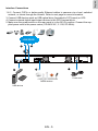
1
2
Physical Description
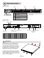
Front View
1
2
3 4
Disk 1
5
1
2
3
4
5
6
6
Disk 2
Power button and LED
Status LED
HDD activity LED
Restore Default button
Backup button
USB
Disk 3
Disk 4 can be installed inside
the chassis.
Rear View
LAN2
LAN1
Fan Outlet
Fan Outlet
GPIO
terminal block
USB 1 & 2
1
DO+ (12V)
6
DI2-
11
Power button
2
DO-
7
DI3+
12
GND
RS232_TX
3
DI1+
8
DI3-
13
4
DI1-
9
DI4+
14
RS232_RX
5
DI2+
10
DI4-
15
GND
16
Power Switch
Power Cord
Socket
GND
IMPORTANT:
It is important to leave a clearance of
10cm to the rear side of the chassis.
The clearance is required to ensure an
adequate airflow through the chassis to
ventilate heat. A 5cm clearance is also
required on the front of the chassis.
10cm
To ensure normal operation, maintain
ambient airflow. Do not block the airflow
around chassis such as placing the system in a closed cabinet.
5cm
EN - 2