1
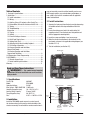
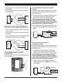
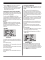
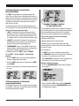
INSTALLER’S & OWNER’S MANUAL
DEH 3000R
HVAC INSTALLER: PLEASE LEAVE MANUAL FOR HOMEOWNER
DEH 3000R
Part No. 4028407
Dehumidifier & Ventilation System Controller
4201 Lien Rd Madison, WI 53704 • TOLL-FREE 1-800-533-7533 • www.thermastor.com • [email protected]
© 2008 Therma-Stor LLC • Manual P/N TS-506c
Table of Contents
may not accurately sense the relative humidity such as near
HVAC supply registers, near exterior doors and windows, or
near a pool or spa. Install in accordance with all applicable
codes and standards.
1. Contents & Specifications................................................ 2
2. Installation....................................................................... 2
2.1 Install Instructions....................................................... 2
2.2 Wiring......................................................................... 3
2.3 Auxiliary Relay, A/C Lockout or Run Central Fan........... 3
2.4 Dehumidifier, Activate/De-Activate with A/C Unit.......... 4
2.5 Testing........................................................................ 5
2.6 Troubleshooting........................................................... 5
3. Operation........................................................................ 6
3.1 Display........................................................................ 6
3.2 Setting........................................................................ 6
3.3 Personal Settings reference......................................... 6
3.4 On/Off and Display items............................................. 6
3.5 Setting Clock Time...................................................... 6
3.6 Adjusting the Relative Humidity Setpoint..................... 7
3.7 Fan Setting & Operation.............................................. 7
3.8 Damper Operation and Ventilation,
Manual (Hold) mode.......................................................... 8
3.9 Damper Operation and Ventilation,
Programmed Ventilation.................................................... 8
4.0 Temperature Cutout Programming................................. 9
5.0 DEH3000R................................................................... 10
5.1 Remote Sensor Usage.............................................. 10
5.2 Install and Wiring Instructions................................... 10
Warranty............................................................................ 11
2.1 Install Instructions
1.Separate the front panel from the back panel by depressing
the middle sections of the top and bottom of the front
panel.
2.Locate the wiring access hole in the wall or other flat
mounting surface. Place the back panel into position and
drill the appropriate mounting holes.
3.Insert the screws and tighten. Level as necessary.
4.Make the electrical connections to the terminals on the
back panel as shown in the applicable wiring diagram (see
Sections 2.2-2.4).
5. Test the installation (see Section 2.5).
Mounting Hole
Read and Save These Instructions
WARNING! — This symbol means important
instructions. Failure to heed them can result in serious
injury or death.
1. Specifications
Part # (P/N): Model: Operating Voltage: Max Current - DMP, COMP, FAN
Humidity Range/Accuracy: Auxillary Relay Capacity:
Temp Range/Accuracy: Size: Mounting Hole
4028407
DEH 3000R
24 VAC
1 AMP each
10 – 95% RH, ± 5%
5 Amps, 24VAC
30°-90°F, 2%
4.95"L x 1.06"W x 4.19"H
24 VAC Yellow Wire
Optional
Use
2. Installation
Install the DEH 3000R remote sensor in a central area of
the structure where it will sense the relative humidity of the
structure accurately. Do not install the remote sensor where it
24 VAC Red Wire
Normally Open
ON-Detect
Common
Common
Normally Closed
OFF-Detect
Optional
Use
Damper Dehumidifier
Fan
White Wire
Blue Wire Green Wire
(Optional. See
warning below)
DEH 3000R Dehumidifier & Ventilation System Controller
2
Installation, Operation & Service Manual
2.2 Wiring
The White wire controls the optional motorized damper
that can be installed into a fresh air duct. This damper
provides the ability to control fresh air ventilation using
the ventilation timer function of the DEH 3000R and
the terminal labeled “DMP” on the DEH 3000R (See
Section 3.8). Leave the “DMP” terminal unused if a
motorized damper is not used, and cap off the White
wire from the Ultra-Aire dehumidifier.
WARNING! DO NOT ALLOW THE YELLOW
WIRE FROM THE ULTRA-AIRE DEHUMIDIFIER TO CONTACT
THE RED OR WHITE WIRES FROM THE ULTRA-AIRE
DEHUMIDIFIER, DAMAGE TO THE 24-VOLT TRANSFORMER
WILL RESULT.
WARNING! THE REMOTE CONTROL OF THE
Standard wire colors for thermostats are as follows:
ULTRA-AIRE DEHUMIDIFIER OPERATES ON A LOW VOLTAGE
CIRCUIT (24 VAC) AND MUST NEVER CONTACT OR BE
CONNECTED TO A HIGH VOLTAGE CIRCUIT.
Description
Color
Terminal code
24VAC RedR
WARNING! UNPLUG THE ULTRA-AIRE
Call for Heat
White
W or W1
DEHUMIDIFIER BEFORE WIRING THE DEH 3000R.
Force Fan On
Green
G
The installer must supply all field wiring, including the
wiring between the Ultra-Aire dehumidifier and the DEH
3000R. Some of the control wires leaving the Ultra-Aire may
not be used in some control situations and should be left
disconnected with wire nuts taped onto the stripped ends.
Compressor
Call for Cooling
Yellow
Y or Y1
2.3 Auxiliary relay operation
It may be desirable to coordinate fan operation of the central
heating/cooling system with dehumidifier operation. The DEH
3000R contains a relay that provides this ability.
Be sure to consult the electrical schematic in this manual or
the internal electrical box of the Ultra-Aire dehumidifier before
making any control connections.
NO
COM
NC
The relay terminals labeled NC, COM and NO operate according
to the following chart:
WARNING! ONLY CONNECT THE WHITE WIRE
TO THE CONTROL IF IT IS WIRED IN A CIRCUIT THROUGH
AN ELECTRIC DAMPER, OTHERWISE TRANSFORMER
DAMAGE MAY RESULT.
DEH 3000R Dehumidifier & Ventilation System Controller
DEHUMIDIFIER
COM to NO
COM to NC
ON
CONNECTED
OPEN
OFF OPEN
CONNECTED
Common uses (assuming standard thermostat wiring colors as
noted):
Lock-out the A/C during dehumidification
This will turn off the A/C whenever the dehumidifier runs.
3
Installation, Operation & Service Manual
A/C
Unit
Greento the NC terminal on
1. Wire the Yellow thermostat terminal
the DEH 3000R.
Yellow
Red
Activate dehumidification when the air-conditioner
is running
A voltmeter is required for the next steps to ensure the correct
wiring from the A/C transformer is used to set up the Lock-in
dehumidifier function.
2. Run the Yellow wire from the A/C unit to the COM terminal
on the DEH 3000R.
Red
Green
1. The common wire from the existing A/C transformer (usually
Black) must be attached to the "COM" sensor terminal
between "ON-D" and "OFF-D" on the DEH 3000R.
A/C
Unit
TIP: The common wire can be identified as the wire
from the A/C transformer that reads 0 volts between it
and the Yellow air conditioning call for cooling wire.The
incorrect wire will give a 20 to 28 volt reading.
Yellow
2. Another Yellow wire must be added to the thermostat Yellow
terminal and run to the “ON-D” sensor terminal on the DEH
3000R.
Energize the A/C central fan during dehumidification
To automatically run the A/C FAN when the dehumidifier runs.
1. Attach a second Green wire to the Green fan wire terminal
on the thermostat.
2. Connect the new Green wire to the COM terminal on the
DEH 3000R.
3. Run a wire from the Red terminal on the thermostat to the
NO (Normally Open) terminal on the DEH 3000R.
Red
Green
TO A/C
Deactivate dehumidification when the
air-conditioner is running
A voltmeter is required for the next steps to ensure the correct
wiring from the A/C transformer is used to set up the Lock-out
dehumidifier function.
A/C
Unit
Yellow
1.The common wire from the existing A/C transformer
(usually Black) must be attached to the "COM" sensor
TO DEH
A/C 3000R.
terminal between "ON-D" and "OFF-D" on the
2.4 Dehumidifier lock-OFF or lock-ON:
A/C sensor feature
To automatically activate or deactivate the dehumidifier when
the air conditioner runs.
Red
A/C
Unit
TIP: The common wire can be identified as the wire
from the A/C transformer that reads 0 volts between it
TO A/CThe
and the Yellow air conditioning call for cooling wire.
incorrect wire will give a 20 to 28 volt reading.
Green
2. Another Yellow wire must be added to the thermostat
Yellow terminal and run to the “OFF-D” sensor terminal on
the DEH 3000R.
Yellow
ON-D
COM
OFF-D
TO A/C
DEH 3000R Dehumidifier & Ventilation System Controller
4
Installation, Operation & Service Manual
2.5 Testing
d. R
elease the “VENT” button, then press it again to switch
vent mode to “OPEN”.
Verify the wiring connections.
e. C
onfirm that the Ultra-Aire fan is ON. Ventilation damper is
OPEN. Ultra-Aire compressor must be OFF.
WARNING! ONLY CONNECT THE WHITE WIRE
TO THE CONTROL IF IT IS WIRED IN A CIRCUIT THROUGH AN
ELECTRIC DAMPER, OTHERWISE TRANSFORMER DAMAGE
MAY RESULT.
f. P ress and hold the “VENT” button until the “OPEN”
flashes on the display.
g. R
elease the “VENT” button, then press it again to switch
vent mode to “CLOSED”.
After checking the wiring, this short test will confirm proper
hook-up.
WARNING! DO NOT MAKE ANY OTHER
1. Install front cover of the DEH 3000R; connect the top first,
then the bottom.
CONNECTIONS OR TRANSFORMER DAMAGE MAY RESULT.
2. Plug in the Ultra-Aire dehumidifier. The DEH 3000R should
power up.
7. Verify any additional optional control operations such as fan
interlock or A/C lockout.
3. Turn the DEH 3000R ON by pressing the “ON/OFF” button.
8. Proceed to the Operation section.
4. Verify dehumidification operation by adjusting the RH
“SETPOINT” to below the “%RH” reading on the display.
Use the down “RH” button. Confirm Ultra-Aire fan and
compressor operation. Both should be ON now.
2.6 Troubleshooting
FOR THE HVAC PROFESSIONAL:
n No display on initial start up.
Note: This is often the result of a drained capacitor. The
capacitor will recharge once power is applied or re-applied to
the unit.
Increase the RH “SETPOINT” on the display to well above the
“%RH” reading on the display. Press the “RH” up arrow to
increase the RH “SETPOINT”.
After running the dehumidifier compressor the DEH 3000R
applies a 10 minute restart lockout on all functions. You will
have to wait for the restart lockout to expire.
– Verify unit has power.
– Turn unit off then on.
5. Verify FAN-only operation:
a. C
heck the “VENT” mode on the display, it will either
be “CLOSED” or “OPEN”. If it is “CLOSED” go to the
next step. If it is “OPEN”, press and hold the “VENT”
key until “OPEN” flashes on the display, release the key
and then press it one more time. “OPEN” will change to
“CLOSED”. Don’t touch the keys for several seconds until
it stops flashing.
– Disconnect the unit from power source then re-apply
power to the unit. Display should now operate.
n Function
not working properly.
– Verify wiring.
– Verify voltage with voltmeter.
n Dehumidifier not working properly.
– See chart below:
b. Press and hold the “FAN” button until “AUTO” begins
flashing on the display, release it, and then press it again
to switch the fan to the “ON” setting.
c. Confirm that the Ultra-Aire fan is ON. Ultra-Aire
compressor must be OFF. Ventilation damper (if used)
should be CLOSED.
Wire connections Operation
Yellow & Blue Fan & Compressor
Yellow & Green
Fan Only
6. Verify optional VENT operation (if electric damper is installed):
a. P ress and hold the “FAN” button until “ON” flashes on
the display.
b. Release the “FAN” button, then press it again to switch
fan operation to “AUTO”.
c. Press and hold the “VENT” button until “CLOSED”
flashes on the display.
DEH 3000R Dehumidifier & Ventilation System Controller
5
Installation, Operation & Service Manual
FOR INSTALLER & HOMEOWNER:
seconds, the control will remember any changes made and
return to the normal display screen, allowing you to proceed to
the next step.
3. Operation
On the display screen, a solid “O” in front of any of the 3
functions (SETPOINT, VENT, FAN) indicates the function is
operating. A flashing “O” indicates it is in a wait mode and
not available at the moment. No “O” indicates the function is
currently OFF.
Function
Factory setting
SETPOINT (%RH)
50%
Solid “O” before
VENTClosed
3.3 Personal Settings reference list
Please record your settings here.
Indicates
SETPOINT
Dehumidifier on
VENT
Fresh air ventilation cycle in progress
FAN
Fan on
My Setting
FANAuto
TEMP CUTOUT 99° 3.4 On/Off and display items
Wait mode is a factory-programmed time period meant to
prevent short cycles. This extends the life of the dehumidifier.
When a flashing “O” is encountered, the unit is in wait mode
and IT COULD BE UP TO 10 MINUTES BEFORE OPERATION
RESUMES.
Press the “ON/OFF” button to turn the system ON or OFF.
When the system is ON, the setpoint, fan status, operation mode
(RUN or HOLD), and fresh air vent status is displayed.
3.1 Display
• Whenever there is power to the control, it will display the time,
the day, % relative humidity, and temperature.
• When the control is actually switched ON, the %RH setpoint,
fan status, run mode (program or hold), and fresh air
ventilation status is displayed.
When the system is OFF, the control will display the time, day,
%RH, and temperature.
When the unit is shipped, it is in manual (hold) mode.
• When a key is pressed the display will light for approximately
½ a minute.
• The Time and Day is displayed at the top of the screen.
• RH and Temperature are displayed in real time.
3.5 Setting Clock Time
• A solid “O” before the SET POINT, VENT, OR FAN indicates the
function is operating.
1. P ress and hold the “CLOCK” button. The hour display will
flash. Release the button.
• A flashing “O” before the SET POINT, VENT, OR FAN indicates
the unit is in wait mode.
2. U
se the up/down “RH” buttons to change the value.
3.2 Setting
3. P ress the “CLOCK” button again and the minute display will
flash. Use the “RH” buttons to change the value.
During the set-up process, if you make a mistake, simply
continue. You can always go back to adjust the settings. If you
leave the control alone and don’t touch any buttons for 10
DEH 3000R Dehumidifier & Ventilation System Controller
4. P ress the “CLOCK” button again and AM or PM will flash.
Use the “RH” buttons to change the value.
6
Installation, Operation & Service Manual
3.7 Fan Setting and Operation
5. P ress the “CLOCK” button again and the day display will
flash. Use the “RH” buttons to change the value.
Use the “FAN” button to change the fan operation. There are 2
choices for fan operation: “ON” or “AUTO”. The factory preset
is “AUTO”.
6. D
on’t touch any buttons for several seconds until the display
stops flashing, this will save your settings. If you need to
change anything go back to step #1.
“ON” –The fan in the Ultra-Aire dehumidifier will run
continuously. This does not affect either the dehumidification
or ventilation functions of the system. The system may or may
not be ventilating or dehumidifying while the fan is running. This
setting is commonly used for maximum air filtration and/or air
recirculation.
3.6 Adjusting the relative humidity “SETPOINT”
The DEH 3000R senses the ambient relative humidity (%RH) of
the space where the remote sensor is located. It comes factory
preset to hold 50% relative humidity.
The relative humidity “SETPOINT” (desired RH to be
maintained) operates the dehumidifier function of the Ultra-Aire
dehumidifier. It has no effect on the optional VENT (fresh air
ventilation) or FAN (household air recirculation) functions if they
are being used.
“AUTO” – Indicates the fan will run when the DEH 3000R calls
for dehumidification or ventilation. If the control has not called
for dehumidification for 3 hours, the control will automatically
run the dehumidifier fan for 10 minutes.
After a dehumidification cycle, the fan automatically shuts off
for 10 minutes. This pause allows the water to drain from the
dehumidifier.
Operation
The standard range that the dehumidifier holds around your
“SETPOINT” is 3%. With a setpoint of 50%, the dehumidifier
will run until the relative humidity reaches 47%. The
dehumidifier will then switch off until the relative humidity
reaches 53%.
A solid “O” indicates the fan is operating. A flashing “O”
indicates the fan is in a wait mode. No “O” indicates the fan is
OFF.
To set the operation:
1. P ress and hold the “FAN” button. The current fan setting will
begin to flash on the display. Release the button.
2. P ress the “FAN” button to toggle between the “ON” and
“AUTO” modes.
If the setpoint is higher than the ambient relative humidity, the
space does not need to be dehumidified so the dehumidifier will
not run.
Example: Setpoint: 50% RH
With the fan in the “AUTO” mode, the fan will operate only
when needed by other functions of the system. The fan will
remain OFF unless the system is dehumidifying or ventilating.
The fan always runs during dehumidification and ventilation and
the fan “O” icon will be lit. To completely turn the system OFF,
use the “ON/OFF” button as described earlier.
Current condition: 45% RH –The dehumidifier will be off (no “O”
indicator will be displayed).
If your setpoint is below the ambient condition, the dehumidifier
will be on and “O” will display.
Example: Setpoint: 50% RH
Current condition: 55% RH –The dehumidifier will be on (“O”
displayed).
DEH 3000R Dehumidifier & Ventilation System Controller
7
Installation, Operation & Service Manual
3.8 Damper Operation and Ventilation,
Manual (Hold) Mode
The “VENT” setting controls the ventilation function of the
system. It has no control over the dehumidification function. In
order to provide ventilation, the motorized damper must be open
and the fan must be running. The controller takes care of these
two functions automatically so that whenever the damper is
open, the fan is running.
The ventilation indicator “O” will be displayed whenever the
unit is ventilating. The fan operation indicator “O” will also be lit.
The DEH 3000R will operate fresh air ventilation according to
your ventilation program. The control needs to be programmed
to turn the ventilation function ON and OFF at the desired
intervals. This is done by programming the ventilation timer.
There are three damper operation modes:
1. “OPEN” – hold mode: The damper will be open and the
dehumidifier fan will be continuously operating to introduce
fresh air into the space. Use this mode for continuous fresh
air ventilation. The fan is always on when the damper is open.
There are two programs available for ventilation:
1. Monday through Sunday
2. “CLOSED” – hold mode: The damper will never open, and
the dehumidifier will not ventilate. The fan will still operate
normally for recirculation and dehumidification.
2. Monday through Friday & Saturday/Sunday
Each block of days has a morning schedule and a night
schedule. Morning is the first 12 hours of the day and night is
the second 12 hours.
3. “PROGRAMmed” mode: The DEH 3000R will operate the
motorized damper and the dehumidifier fan according to the
programmed ventilation schedule (Section 3.9).
Each schedule has:
The factory preset for the “VENT” setting is “CLOSED”.
• A “START” time when the ventilation schedule begins,
To set “OPEN” – hold or “CLOSED” – hold ventilation
operation:
1. P ress the “VENT” button. The current setting will begin to
flash on the display. Release the button.
• An “OPEN FOR” duration for the amount of time the damper
stays open in 5 minute intervals, from 0 to 60,
2. P ress the “VENT” button again to switch between “OPEN”
and “CLOSED”.
Setting the Ventilation Program:
1. P ress the “PROGRAM ENTER” button until the following
menu appears:
• And “CLOSED FOR” duration which closes the damper for a
specified time in 5 minute intervals from 0 to 60.
3. L eave the control alone for 10 seconds and your settings will
be saved.
3.9 Damper Operation and Ventilation,
Programmed Ventilation
2. U
sing the up/down “RH” buttons, highlight “PROGRAM”
and select it by pressing the “PROGRAM enter” button.
The following menu appears:
This example shows the system in program mode (denoted by
the schedule 15 minutes on, 5 minutes off and the word RUN in
the lower right corner of the display).
DEH 3000R Dehumidifier & Ventilation System Controller
8
Installation, Operation & Service Manual
7-day version or the weekday/weekend split version), use the
down “RH” button to highlight the EXIT option and then press
“PROGRAM ENTER” to select it.
Running the Ventilation Program
Press and hold the “PROGRAM ENTER” button until the
“PROGRAM” screen appears.
Use the down “RH” button to highlight “RUN PROGRAM”:
You can select from:
“MON-FRI” “SAT-SUN” for separate weekday and weekend
schedules, or “MON-SUN” which gives you equal weekday and
weekend schedules.
3. Using the Up/Down “RH” buttons, highlight and then select
one of the two choices. The example given shows how to
program separate weekday and weekend schedules. The same
method is used if you choose the other program.
Then press “PROGRAM ENTER” to select it. The display will
appear as follows:
Example: menu when you select “MON-FRI” “SAT-SUN”:
1. E nter the starting time for weekdays using the up/down “RH”
buttons to change the time.
2. P ress the “PROGRAM enter” button to switch to the
“OPEN FOR” setting. Using the up/down “RH” buttons,
change the duration that the damper will ventilate fresh air.
4.0 Temperature Cutout Programming
Dehumidifiers produce heat when dehumidifying and depending
upon outside conditions, the ventilation function may also
introduce warm air. Some conditions may introduce enough
heat to drive household temperatures up. The DEH 3000R
temperature cutout feature disables all Ultra-Aire operations if
household temperatures reach the cutout setpoint.
3. P ress the “PROGRAM ENTER” button to switch to the
“CLOSED FOR” setting. Using the up/down “RH” buttons,
change the duration that the damper will remain closed
between ventilation cycles.
For the example given, starting at 8:00AM in the morning, the
control will ventilate fresh air for 15 minutes then stop for 15
minutes. This schedule of 15 minutes open, 15 minutes closed
will continue until the start time of the night schedule.
In most installations this feature will not need to be used (the
cutout is factory set to 99°F). If a lower temperature cutout
is desired, program the setpoint by pressing and holding the
“PROGRAM ENTER” button until the “PROGRAM” screen
appears. Press the up/down “RH” buttons until “TEMP
CUTOUT” highlighted. Then press the “PROGRAM ENTER”
button again to select it. Now use the “RH” up or “RH” down
buttons to adjust the setpoint. Press “PROGRAM ENTER” to
return to the home screen.
Morning schedule is available anytime from 12:00AM until
11:59AM.
Night schedule is available anytime from 12:00PM until
11:59PM.
4. Press “PROGRAM ENTER” again to go to the “MON-FRI”
night schedule. Repeat the steps listed above for this and the
“SAT-SUN” day and night schedules.
When you have finished programming your schedule (either the
DEH 3000R Dehumidifier & Ventilation System Controller
9
Installation, Operation & Service Manual
5.0 DEH3000R — Remote sensor option. This section is applicable only to customers who have
purchased a remote sensor package. The standard DEH 3000R controller does not offer remote
functionality.
5.1 Remote Sensor Usage
limit sensor distance. Thicker gauges will not work with
splice connectors provided.
IMPORTANT!
• Avoid routing parallel to high voltage wiring.
• The use of spray paint on the sensor housing may damage
the sensor and is not covered by the product warranty.
• Maintain a distance of 2 ft. or more from high voltage lines.
2. Sensor connection:
The sensor can be mounted to a wall or ceiling surface.
Ideal sensor location is 5 ft. above the floor. Wires should
exit through a ½” diameter hole in the mounting surface at
the mounting location. Use the provided splice connectors to
connect the 4 wires from the remote sensor to the usersupplied interconnect wire. Be sure to keep proper colors
attached to each other.
The remote sensing option is used when an installation
requires mounting the DEH 3000R out of the conditioned
space or when it is desired to specifically monitor and
control the conditions at a particular location in a larger
conditioned space.
Both the need for and location of the remote sensor should
be determined by a heating/cooling professional. In most
installations, the onboard sensor in the DEH 3000R will be
sufficient to monitor and control the conditioned space.
3. Sensor mounting:
You will need two screws to mount the sensor. Use the two
slotted holes to mount the base of the sensor to the wall and
then snap the cover into place.
5.2 Install and Wiring Instructions
1. Routing signal wires:
You will be required to supply and route 24 gauge, 4
conductor solid wire (2-line telephone wire) between the
DEH 3000R controller and the remote sensor location. The
wiring run should be no longer than 100 ft. Avoid routing
this interconnect wire parallel to high voltage wiring.
Maintain a distance of 2 ft. or more from high voltage lines.
4. Controller connection:
Use the provided splice connectors to connect the 4 wires
from the DEH 3000R to the user-supplied interconnect wire.
Be sure to keep the proper colors attached to each other.
Continue with the installation as described in the rest of this
manual.
• Do not run wires longer than 100 ft.
• The use of 24 gauge wire is optimal. Thinner gauge wire
may
DEH 3000R Dehumidifier & Ventilation System Controller
10
Installation, Operation & Service Manual
DEH 3000R
DEH 3000R
Dehumidifier & Ventilation System Controller
Limited Warranty. Therma-Stor, LLC (“Therma-Stor”) warrants
as follows: (i) the DEH 3000R (“Product”) will be free of material
defects in workmanship or materials for a period of three (1) year
(“One-Year Warranty”) following the date of initial purchase of such
Product by an original customer purchasing from Therma-Stor or an
authorized reseller (“Customer”); and (ii) the Product’s condenser,
evaporator, and compressor will be free of material defects in
workmanship or materials for a period of five (5) years following the
date of initial purchase of such Product by a Customer.
Customer Responsibilities. As a further condition to obtaining
warranty coverage hereunder, the Customer must send a valid
warranty claim to Therma-Stor such that Therma-Stor receives
such claim prior to the end of the applicable warranty period.
Therma-Stor shall have no obligation hereunder with respect to
any claim received by Therma-Stor after the expiration of the
applicable warranty period. As a further condition to obtaining
warranty coverage hereunder, the Customer must present forms
of invoices evidencing proof of purchase of a Product. If such
invoices do not clearly indicate the date of initial purchase by a
Customer, the applicable Product’s date of manufacture will be
used instead of the date of initial purchase for the purpose of
calculating the commencement of the applicable warranty period.
Warranty service must be performed by Therma-Stor or a servicer
authorized by Therma-Stor. In order to obtain warranty service, the
Customer should call Therma-Stor at 1-800-533-7533 and ask
for the Therma-Stor Products Service Department, which will then
arrange for applicable warranty service. Warranty service will be
performed during customary, daytime working hours. If the Product
must be shipped for service, Customer shall be solely responsible
for properly packaging the Product, for all freight charges, and for
all risk of loss associated with shipment.
Limitation of Remedies. CUSTOMER’S SOLE AND EXCLUSIVE
REMEDY UNDER THE ABOVE LIMITED WARRANTY AND THERMASTOR’S ENTIRE LIABILITY THEREUNDER, SHALL BE, AT THE SOLE
OPTION OF THERMA-STOR, REPLACEMENT OR REPAIR OF SUCH
PRODUCT OR ITS COMPONENTS (“COMPONENTS”) BY THERMASTOR OR THERMA-STOR’S AGENTS ONLY. REFRIGERANT, PIPING,
SUPPLIES, TRANSPORTATION COSTS, LABOR COSTS INCURRED
IN REPAIR OR REPLACEMENT OF SUCH COMPONENTS ARE NOT
INCLUDED. THIS DISCLAIMER AND EXCLUSION SHALL APPLY
EVEN IF THE EXPRESS WARRANTY AND LIMITED REMEDY SET
FORTH HEREIN FAILS OF ITS ESSENTIAL PURPOSE. CUSTOMER
ACKNOWLEDGES THAT NO REPRESENTATIVE OF THERMA-STOR OR
OF ITS AFFILIATES OR RESELLERS IS AUTHORIZED TO MAKE ANY
REPRESENTATION OR WARRANTY ON BEHALF OF THERMA-STOR
OR ANY OF ITS AFFILIATES OR RESELLERS THAT IS NOT IN THIS
AGREEMENT. Notwithstanding the above, during the term of the
One-Year Warranty only, Therma-Stor will provide, free of charge
to Customer, all Components and labor (except costs related to
removal and installation of Product) required to fulfill its obligations
under such One-Year Warranty.
Limitation of Liability. IN NO EVENT SHALL THERMA-STOR,
IN CONNECTION WITH THE DESIGN, SALE, INSTALLATION, USE,
REPAIR, REPLACEMENT OR PERFORMANCE OF ANY PRODUCT,
COMPONENT, PART THEREOF OR WRITTEN MATERIAL PROVIDED
THEREWITH, BE LIABLE, TO THE EXTENT ALLOWED UNDER
APPLICABLE LAW, UNDER ANY LEGAL THEORY FOR ANY SPECIAL,
DIRECT, INDIRECT, COLLATERAL OR CONSEQUENTIAL DAMAGES
OF ANY KIND. NOTWITHSTANDING THE ABOVE LIMITATIONS AND
WARRANTIES, THE SOLE AND EXCLUSIVE LIABILITY OF THERMASTOR, REGARDLESS OF THE NATURE OR THEORY OF THE CLAIM,
SHALL UNDER NO CIRCUMSTANCES EXCEED THE PURCHASE PRICE
OF THE PRODUCT, COMPONENT OR PART UPON WHICH THE CLAIM
IS PREMISED.
Disclaimer of Warranties. EXCEPT FOR ABOVE LIMITED
WARRANTY, WHICH IS THE SOLE AND EXCLUSIVE WARRANTY
PROVIDED WITH RESPECT TO THE PRODUCT AND ITS
COMPONENTS, THERMA-STOR HEREBY DISCLAIMS ALL EXPRESS
AND IMPLIED WARRANTIES, INCLUDING, WITHOUT LIMITATION, THE
IMPLIED WARRANTIES OF MERCHANTABILITY AND FITNESS FOR A
PARTICULAR PURPOSE.
Applicable Law and Venue. ANY ARBITRATION, ENFORCEMENT
OF AN ARBITRATION OR LITIGATION RELATED TO THE PRODUCT
WILL BE BROUGHT EXCLUSIVELY IN DANE COUNTY, WISCONSIN,
AND CUSTOMER CONSENTS TO THE JURISDICTION OF THE
FEDERAL AND STATE COURTS LOCATED THEREIN, SUBMITS TO
THE JURISDICTION THEREOF AND WAIVES THE RIGHT TO CHANGE
VENUE. CUSTOMER FURTHER CONSENTS TO THE EXERCISE OF
PERSONAL JURISDICTION BY ANY SUCH COURT WITH RESPECT TO
ANY SUCH PROCEEDING.
Warranty Limitations. The foregoing limited warranty extends
only to a Customer and shall be null and void upon attempted
assignment or transfer. A “defect” under the terms of the limited
warranty shall not include problems resulting from Customer’s
or Customer’s employees’, agents’, invitees’ or a third party’s
misuse, improper installation, improper design of any system in
which the Product is included, abuse, lack of normal care, failure
to follow written instructions, tampering, improper repair, or
freezing, corrosion, acts of nature or other causes not arising out of
defects in Therma-Stor’s workmanship or material. If a Product or
Component is replaced while under warranty, the applicable limited
warranty period shall not be extended beyond the original warranty
time period. The limited warranty does not cover any costs related
to changes to a Product or Component that may be required by any
codes, laws, or regulations that may become effective after initial
purchase of the Product by Customer.
DEH 3000R Dehumidifier & Ventilation System Controller
Miscellaneous. If any term or condition of this Limited Warranty
is found by a court of competent jurisdiction to be invalid, illegal
or otherwise unenforceable, the same shall not affect the other
terms or conditions hereof or thereof or the whole of this Limited
Warranty. Any delay or failure by Therma-Stor to exercise any right
or remedy will not constitute a waiver of Therma-Stor to thereafter
enforce such rights.
11
Installation, Operation & Service Manual
4201 Lien Rd • Madison, WI 53704
Phone: 608-222-5301 • Fax: 608-222-1447
www.thermastor.com • [email protected]
Information in this document is subject to change without notice. No part of
this document may be reproduced or transmitted in any form or by any means,
electronic or mechanical, for any purpose, without the express written permission
of Therma-Stor LLC. © 2007 Therma-Stor LLC. All rights reserved.
DEH 3000R Dehumidifier & Ventilation System Controller
Installation, Operation & Service Manual