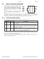
1
Flasher STM8
User guide of the stand-alone
SWIM programmer for STM8 Cores
Manual Rev. 8
Date: May 2, 2011
Document: UM05006
A product of SEGGER Microcontroller GmbH & Co. KG
www.segger.com
2
Disclaimer
Specifications written in this document are believed to be accurate, but are not guaranteed to be entirely free of error. The information in this manual is subject to
change for functional or performance improvements without notice. Please make sure
your manual is the latest edition. While the information herein is assumed to be
accurate, SEGGER Microcontroller GmbH & Co. KG (the manufacturer) assumes no
responsibility for any errors or omissions. The manufacturer makes and you receive
no warranties or conditions, express, implied, statutory or in any communication with
you. The manufacturer specifically disclaims any implied warranty of merchantability
or fitness for a particular purpose.
Copyright notice
You may not extract portions of this manual or modify the PDF file in any way without
the prior written permission of the manufacturer. The software described in this document is furnished under a license and may only be used or copied in accordance
with the terms of such a license.
© 2011 SEGGER Microcontroller GmbH & Co. KG, Hilden / Germany
Trademarks
Names mentioned in this manual may be trademarks of their respective companies.
Brand and product names are trademarks or registered trademarks of their respective holders.
Contact address
SEGGER Microcontroller GmbH & Co. KG
In den Weiden 11
D-40721 Hilden
Germany
Tel.+49 2103-2878-0
Fax.+49 2103-2878-28
Email: [email protected]
Internet: http://www.segger.com
Flasher STM8 (UM05006)
© 2011 SEGGER Microcontroller GmbH & Co. KG
3
Revisions
This manual describes the Flasher STM8 device.
For further information on topics or routines not yet specified, please contact us.
Revision
Date
By
8
110502
OO
7
110307
OO
6
101007
OO
5
100702
OO
4
100624
OO
3
100607
OO
2
100525
OO
1
100401
OO
0
091210
OO
Flasher STM8 (UM05006)
Explanation
Chapter "Hardware":
- Some minor changes.
- Added more detailed information about the connection cable.
Chapter "Introduction":
- Added speed measurements
Chapter "Working with Flasher STM8":
- Added example for setting up multiple configurations for stand-alone mode and how to switch
between configurations remotely.
Chapter "Remote control":
- Added information regarding TCP/IP terminal
Updated document to renamed binaries in Flasher
STM8 software and documentation package.
Updated all screenshots.
Chapter "Hardware":
- Added information about connecting Flasher GND
to power supply ground for more power stabilization
Chapter "Hardware":
- Added more information to SWIM and Reset output signals
- Some minor changes
Chapter "Working with Flasher STM8":
- Added information about setup multiple Flasher
on one PC
Chapter "Hardware":
- Declared 10-pin connector as obsolete interface
Initial version.
© 2011 SEGGER Microcontroller GmbH & Co. KG
4
Flasher STM8 (UM05006)
© 2011 SEGGER Microcontroller GmbH & Co. KG
5
About this document
This document describes the Flasher STM8. It provides an overview over the major
features of the Flasher STM8, gives you some background information about SWIM,
STM8 general and describes Flasher STM8 related software packages available from
Segger. Finally, the chapter Support and FAQs on page 65 helps to troubleshoot common problems.
Typographic conventions
This manual uses the following typographic conventions:
Style
Used for
Body
Body text.
Keyword
Text that you enter at the command-prompt or that appears on the
display (that is system functions, file- or pathnames).
Reference
Reference to chapters, tables and figures or other documents.
GUIElement
Buttons, dialog boxes, menu names, menu commands.
Table 1.1: Typographic conventions
Flasher STM8 (UM05006)
© 2011 SEGGER Microcontroller GmbH & Co. KG
6
SEGGER Microcontroller GmbH & Co. KG develops
and distributes software development tools and ANSI
C software components (middleware) for embedded
systems in several industries such as telecom, medical technology, consumer electronics, automotive
industry and industrial automation.
SEGGER’s intention is to cut software developmenttime for embedded applications by offering compact flexible and easy to use middleware,
allowing developers to concentrate on their application.
Our most popular products are emWin, a universal graphic software package for embedded applications, and embOS, a small yet efficient real-time kernel. emWin, written
entirely in ANSI C, can easily be used on any CPU and most any display. It is complemented by the available PC tools: Bitmap Converter, Font Converter, Simulator and
Viewer. embOS supports most 8/16/32-bit CPUs. Its small memory footprint makes it
suitable for single-chip applications.
Apart from its main focus on software tools, SEGGER develops and produces programming
tools for flash microcontrollers, as well as J-Link, a JTAG emulator to assist in development, debugging and production, which has rapidly become the industry standard for
debug access to ARM cores.
Corporate Office:
http://www.segger.com
EMBEDDED SOFTWARE
(Middleware)
United States Office:
http://www.segger-us.com
SEGGER TOOLS
emWin
Flasher
Graphics software and GUI
emWin is designed to provide an efficient, processor- and display controller-independent graphical user
interface (GUI) for any application that
operates with a graphical display.
Starterkits, eval- and trial-versions are
available.
Flash programmer
Flash Programming tool primarily for microcontrollers.
J-Link
embOS
JTAG emulator with trace
USB driven JTAG interface for ARM cores with
Trace memory. supporting the ARM ETM (Embedded Trace Macrocell).
Real Time Operating System
embOS is an RTOS designed to offer
the benefits of a complete multitasking
system for hard real time applications
with minimal resources. The profiling
PC tool embOSView is included.
emFile
JTAG emulator for ARM cores
USB driven JTAG interface for ARM cores.
J-Trace
J-Link / J-Trace Related Software
Add-on software to be used with SEGGER’s industry standard JTAG emulator, this includes flash
programming software and flash breakpoints.
File system
emFile is an embedded file system with
FAT12, FAT16 and FAT32 support.
emFile has been optimized for minimum memory consumption in RAM and
ROM while maintaining high speed.
Various Device drivers, e.g. for NAND
and NOR flashes, SD/MMC and CompactFlash cards, are available.
emUSB
USB device stack
A USB stack designed to work on any
embedded system with a USB client
controller. Bulk communication and
most standard device classes are supported.
Flasher STM8 (UM05006)
© 2011 SEGGER Microcontroller GmbH & Co. KG
7
Table of Contents
1 Introduction ......................................................................................................................9
1.1
1.1.1
1.1.2
1.2
1.2.1
1.3
1.4
1.5
Flasher STM8 overview............................................................................. 10
Features of Flasher STM8.......................................................................... 10
Working environment ............................................................................... 10
Specifications.......................................................................................... 11
Specifications for Flasher STM8 ................................................................. 11
Flasher STM8 features .............................................................................. 12
Supported CPU cores ............................................................................... 13
Download speed ...................................................................................... 14
2 Setup..............................................................................................................................15
2.1
2.1.1
2.2
2.2.1
2.3
2.4
2.4.1
2.4.2
Installing the Flasher STM8 software and documentation pack ....................... 16
Setup procedure...................................................................................... 16
Setting up the USB interface ..................................................................... 19
Verifying correct driver installation ............................................................. 19
Uninstalling the J-Link USB driver .............................................................. 21
Setting up the IP interface ........................................................................ 22
Connecting the first time .......................................................................... 22
Configuring the Flasher ............................................................................ 23
3 Flasher STM8 related software......................................................................................27
3.1
3.2
3.2.1
3.2.2
3.3
3.3.1
3.3.2
3.3.3
Flasher STM8 software and documentation package ..................................... 28
Flasher STM8 software and documentation package in detail ......................... 29
STM8 Commander (Command line tool)...................................................... 29
Flasher STM8 Software (Program flash memory).......................................... 30
Using the JLinkSTM8.dll ............................................................................ 31
What is the JLinkSTM8.dll?........................................................................ 31
Determining the version of JLinkSTM8.dll .................................................... 31
Determining which DLL is used by a program .............................................. 32
4 Working with Flasher STM8...........................................................................................33
4.1
4.1.1
4.1.2
4.1.3
4.2
4.2.1
4.3
4.3.1
4.3.2
4.3.3
Operating modes ..................................................................................... 34
PC mode ................................................................................................ 34
Stand-alone mode ................................................................................... 37
MSD mode.............................................................................................. 38
Multiple File Support ................................................................................ 39
Setting up configurations and switching configurations ................................. 40
Connecting multiple Flasher to your PC ....................................................... 44
How does it work? ................................................................................... 44
Configuring multiple Flasher STM8 ............................................................. 45
Connecting to a Flasher with non default USB-Address.................................. 46
5 Remote control...............................................................................................................47
5.1
5.2
5.3
5.3.1
5.3.2
5.3.3
Overview ................................................................................................ 48
Handshake control ................................................................................... 49
ASCII command interface ......................................................................... 50
Introduction............................................................................................ 50
General command and reply message format .............................................. 50
Communication port settings..................................................................... 50
Flasher STM8 (UM05006)
© 2011 SEGGER Microcontroller GmbH & Co. KG
8
5.3.4
5.3.5
Commands to Flasher .............................................................................. 50
Reply from Flasher STM8.......................................................................... 54
6 Hardware .......................................................................................................................57
6.1
6.1.1
6.2
6.2.1
6.3
6.4
6.4.1
6.5
10-pin connector (obsolete)...................................................................... 58
10-pin connector pinout ........................................................................... 58
4-pin Connector ...................................................................................... 59
4-pin connector pinout ............................................................................. 59
Connection cable..................................................................................... 60
Target board design for SWIM................................................................... 61
Target power supply ................................................................................ 61
How to determine the hardware version ..................................................... 62
7 Background information .................................................................................................63
7.1
7.1.1
7.1.2
7.1.3
Flash programming ................................................................................. 64
How does flash programming via Flasher STM8 work ? ................................. 64
Data download to RAM ............................................................................. 64
Available options for flash programming ..................................................... 64
8 Support and FAQs .........................................................................................................65
8.1
8.2
Contacting support .................................................................................. 66
Frequently Asked Questions...................................................................... 67
9 Glossary.........................................................................................................................69
10 Literature and references.............................................................................................71
Flasher STM8 (UM05006)
© 2011 SEGGER Microcontroller GmbH & Co. KG
9
Chapter 1
Introduction
This chapter gives a short overview about the Flasher STM8.
Flasher STM8 (UM05006)
© 2011 SEGGER Microcontroller GmbH & Co. KG
10
CHAPTER 1
1.1
Introduction
Flasher STM8 overview
Flasher STM8 is a programming tool for microcontrollers with on-chip Flash memory
and STM8 core. Flasher STM8 is designed for programming flash targets with a PC
program or stand-alone.
Flasher STM8 connects via USB, via ethernet or via RS232 interface to a PC, running
Microsoft Windows 2000, Windows XP, Windows 2003, Windows Vista or Windows 7.
Flasher STM8 has a built-in 10-pin interface connector and a built-in 4-pin interface
connector, which are compatible with the debug connectors used by STM8 eval systems.
1.1.1
•
•
•
•
•
•
•
1.1.2
Features of Flasher STM8
Three boot modes: PC mode, stand-alone mode, MSD mode
Stand-alone SWIM programmer (Once set up, Flasher can be controlled without
the use of PC program)
No power supply required, powered through USB
Support for all STM8 devices
128 MB memory for storage of target program
Serial in target programming supported
Data files can be updated via PC program
Working environment
General
Flasher STM8 can be operated from a PC with an appropriate software like Flasher
STM8 software or in stand-alone mode.
Host System
IBM PC/AT or compatible. CPU: Pentium with at least 192MB of RAM, running
Microsoft Windows 2000, Windows XP, Windows 2003, Windows Vista or Windows 7.
It needs to have an USB, ethernet or RS232 interface available for communication
with Flasher STM8.
Power supply
Flasher requires 5V DC, min. 100mA via USB connector. If USB is not connected, the
USB connector is used to power the device. Supply voltage is the same in this case.
Please avoid excess voltage.
Installing Flasher STM8 PC-software Flasher STM8
The latest version of the Flasher STM8 Software, which is part of the Flasher STM8
software and documentation package, can be downloaded from our website: http://
www.segger.com. For more information about using Flasher STM8 Software please
refer to the Flasher STM8 Software User Guide which is also available for download
on our website.
Flasher STM8 (UM05006)
© 2011 SEGGER Microcontroller GmbH & Co. KG
11
1.2
Specifications
1.2.1
Specifications for Flasher STM8
The following table gives an overview about the specifications (general, mechanical,
electrical) for Flasher STM8.
General
Supported OS
Electromagnetic compatibility (EMC)
Operating temperature
Storage temperature
Relative humidity (non-condensing)
Size (without cables)
Weight (without cables)
Microsoft Windows 2000
Microsoft Windows XP
Microsoft Windows XP x64
Microsoft Windows 2003
Microsoft Windows 2003 x64
Microsoft Windows Vista
Microsoft Windows Vista x64
Windows 7
Windows 7 x64
EN 55022, EN 55024
+5°C ... +60°C
-20°C ... +65 °C
Max. 90% rH
121mm x 66mm x 30mm
122g
Mechanical
USB interface
Ethernet interface
RS232 Host Interface
USB 2.0, full speed
100MHz full duplex
RS232 9-pin
SWIM (either via 10-pin connector or 4pin connector depending on target hardware)
Target interface
SWIM Interface, Electrical
Target interface voltage (VIF)
Target supply voltage
Target supply current
LOW level input voltage (VIL)
USB powered, 100mA for Flasher STM8.
500mA if target is powered by Flasher
STM8.
1.2V ... 5V
4.5V ... 5V (if powered with 5V on USB)
Max. 300mA
Max. 40% of VIF
HIGH level input voltage (V IH)
Min. 60% of V IF
Power supply
Table 1.1: Flasher STM8 specifications
Flasher STM8 (UM05006)
© 2011 SEGGER Microcontroller GmbH & Co. KG
12
CHAPTER 1
1.3
Introduction
Flasher STM8 features
•
•
•
•
•
•
•
•
•
•
•
•
USB 2.0 interface
Full duplex 100Mbit ethernet interface
Any STM8 core supported
No power supply required, powered through USB
Target voltage can be measured
Fully plug and play compatible
Standard 4-pin SWIM connector
USB, ethernet, RS232 and 4-pin ribbon cable included
TCP/IP server included in Flasher STM8, which allows using Flasher via TCP/IP
networks
Flash programming software available
Integrated optical isolation between host and target system
Target power supply via pin 1 of the 4-pin interface (up to 300mA to target with
overload protection)
Flasher STM8 (UM05006)
© 2011 SEGGER Microcontroller GmbH & Co. KG
13
1.4
Supported CPU cores
Flasher STM8 has been designed and tested with the following cores, but should work
with any STM8 core. If you experience problems with a particular core, do not hesitate to contact Segger.
•
•
•
STM8A
STM8L
STM8S
Flasher STM8 (UM05006)
© 2011 SEGGER Microcontroller GmbH & Co. KG
14
CHAPTER 1
1.5
Introduction
Download speed
Flasher STM8 has been designed to allow downloading to the target as fast as the
target can receive and program flash. The table below shows the measured download
speed for standalone programming and for programming via PC driven software. The
following testing environment has been used:
•
•
•
•
•
PC with 2.53 GHz Core2Duo, running WinXP
USB 2.0 port
USB 2.0 hub
Flasher STM8
STM8S208MBT6B
Operation
Program (128kB)
Program and verify (128kB)
Standalone mode
8.5s (15kB/s)
11.3s
PC mode
8.5s (15kB)
11.3s
Table 1.2: Flasher STM8 download speed
Flasher STM8 (UM05006)
© 2011 SEGGER Microcontroller GmbH & Co. KG
15
Chapter 2
Setup
This chapter describes the setup procedure required in order to work with Flasher
STM8. Primarily this includes the installation of the Flasher STM8 software and documentation package.
Flasher STM8 (UM05006)
© 2011 SEGGER Microcontroller GmbH & Co. KG
16
CHAPTER 2
Setup
2.1 Installing the Flasher STM8 software and documentation pack
Flasher STM8 is shipped with a bundle of applications, corresponding manuals and
some sample projects and the kernel mode USB driver.
Refer to chapter Flasher STM8 related software on page 27 for an overview about the
Flasher STM8 software and documentation pack.
2.1.1
Setup procedure
To install the Flasher STM8 software and documentation pack, follow this procedure:
Note:
We recommend to check if a newer version of the Flasher STM8 software
and documentation pack is available for download before starting the installation.
Check therefore the Flasher STM8 related download section of our website.
Before you plug your Flasher STM8 into your computer's USB port, extract the setup
tool Setup_FlasherSTM8_V<VersionNumber>.zip. The setup wizard will install the
software and documentation pack that also includes the certified J-Link USB driver.
Start the setup by double clicking Setup_FlasherSTM8_V<VersionNumber>.exe. The
license Agreement dialog box will be opened. Accept the terms with the Yes button.
1.
The Welcome dialog box is opened. Click Next > to open the Choose Destination Location dialog box.
Flasher STM8 (UM05006)
© 2011 SEGGER Microcontroller GmbH & Co. KG
17
2.
Accept
the
default
installation
path
C:\Program
Files\SEGGER\FlasherSTM8_V<VersionNumber> or choose an alternative location. Confirm
your choice with the Next > button.
3.
The Choose options dialog is opened. The Create entry in start menu option
is preselected. Accept or deselect the options and confirm the selection with the
Next > button.
Confirm start of installation by pressing Next > button again.
4.
The installation process will be started.
Flasher STM8 (UM05006)
© 2011 SEGGER Microcontroller GmbH & Co. KG
18
CHAPTER 2
5.
6.
Setup
The Installation Complete dialog box appears after the copy process. Close the
installation wizard with the Finish > button.
The Flasher STM8 software and documentation pack is successfully installed on
your PC.
Connect your Flasher STM8 via USB with your PC. The Flasher STM8 will be identified and after a short period the Flasher LED stops rapidly flashing and stays on
permanently.
Flasher STM8 (UM05006)
© 2011 SEGGER Microcontroller GmbH & Co. KG
19
2.2
Setting up the USB interface
After installing the Flasher STM8 software and documentation package it should not
be necessary to perform any additional setup sequences in order to configure the
USB interface of Flasher STM8.
2.2.1
Verifying correct driver installation
To verify the correct installation of the driver, disconnect and reconnect Flasher STM8
to the USB port. During the enumeration process which takes about 2 seconds, the
LED on Flasher STM8 is flashing. After successful enumeration, the LED stays on permanently.
Start the provided sample application STM8Commander.exe, which should display the
compilation time of the Flasher firmware, the serial number and a target voltage of
0.000V. The screenshot below shows an example.
In addition you can verify the driver installation by consulting the Windows device
manager. If the driver is installed and your Flasher STM8 is connected to your computer, the device manager should list the J-Link USB driver as a node below "Universal Serial Bus controllers" as shown in the following screenshot:
Flasher STM8 (UM05006)
© 2011 SEGGER Microcontroller GmbH & Co. KG
20
CHAPTER 2
Setup
Right-click on the driver to open a context menu which contains the command Properties. If you select this command, a J-Link driver Properties dialog box is opened
and should report: This device is working properly.
If you experience problems, refer to the chapter Support and FAQs on page 65 for
help. You can select the Driver tab for detailed information about driver provider,
version, date and digital signer.
Flasher STM8 (UM05006)
© 2011 SEGGER Microcontroller GmbH & Co. KG
21
2.3
Uninstalling the J-Link USB driver
If Flasher STM8 is not properly recognized by Windows and therefore does not enumerate, it makes sense to uninstall the J-Link USB driver.
This might be the case when:
•
•
The LED on the Flasher STM8 is rapidly flashing.
The Flasher STM8 is recognized as Unknown Device by Windows.
To have a clean system and help Windows to reinstall the J-Link driver, follow this
procedure:
1.
2.
Disconnect Flasher STM8 from your PC.
Open the Add/Remove Programs dialog (Start > Settings > Control Panel
> Add/Remove Programs) and select Windows Driver Package - Segger
(jlink) USB and click the Change/Remove button.
3.
Confirm the uninstallation process.
Flasher STM8 (UM05006)
© 2011 SEGGER Microcontroller GmbH & Co. KG
22
CHAPTER 2
2.4
Setup
Setting up the IP interface
Flasher STM8 has an additional Ethernet interface, to communicate with the host system. A built-in web server allows configuration of the flasher via web interface. In
addition to that, you can set a default gateway for the flasher which allows using it
even in large intranets. For simplicity the setup process of Flasher STM8 is described
in this section.
2.4.1
Connecting the first time
When connecting Flasher the first time, it attempts to acquire an IP address via
DHCP. To get information about which IP address is acquired, you have two possibilities:
•
•
Connecting Flasher via USB and via Ethernet and read out the IP address via
STM8Commander.exe.
Connecting Flasher only via Ethernet and read out the IP via the DHCP IP Assignment table of your DHCP Server.
In the following, both ways to get the IP address assigned to Flasher via DHCP, are
explained.
2.4.1.1 Connecting via USB and Ethernet
When using STM8Commander.exe in order to read out the IP address, Flasher has to
be connected to your host system via Ethernet and via USB. When starting
STM8Commander.exe, it will show information about the IP address (static / dynamic)
when connecting to Flasher.
To get more detailed information about the current configuration of the Flasher (such
as subnet mask and MAC address), you can use the conf command in
STM8Commander.exe.
After reading out the IP address you can connect to Flasher via Ethernet, using the IP
address.
Flasher STM8 (UM05006)
© 2011 SEGGER Microcontroller GmbH & Co. KG
23
2.4.1.2 Connecting via Ethernet only
This way of reading out the IP address of Flasher can be used for example if you do
not have administrator rights on the host system in order to install the USB driver
which is necessary to connect to Flasher via USB. To get the IP address which has
been assigned to Flasher via DHCP, you have to read it out from the DHCP IP Assignment table of your DHCP Server:
You can easily identify your Flasher by its host ID (in this case FLASHER351100023)
and by its MAC addr which always starts with: 00-22-C7-03-XX-XX where XX depends
on the last five digits of the serial number of your Flasher. In this case the serial
number of the connected Flasher is 351100023 (0x0017), so its MAC address is: 0022-C7-03-00-17.
2.4.2
Configuring the Flasher
By default, Flasher is configured to receive an IP address and a subnet mask via
DHCP. It is also possible to assign a fixed IP address to it. Setting up Flasher can be
done via STM8Commander.exe or via web interface. In the following, both configuration methods are described.
2.4.2.1 Configuring Flasher via STM8Commander.exe
Configuring Flasher via STM8Commander.exe is very simple because only one command (in different variations) is necessary to choose between automatic IP address
and dynamic IP address assignment.
Note:
If you want to configure Flasher via STM8Commander.exe and Flasher is
connected to your host-system via Ethernet only, you have to type in the ip
<IPAddr> command.
Example
ip 192.168.199.29
Assigning an IP address via DHCP
By default, Flasher is configured to acquire an IP address via DHCP, so it should not
be necessary to configure this. But, if you change the IP address to a fixed one,
DHCP is disabled from this point. To re-enable DHCP you should use the ipaddr DHCP
command in STM8Commander.exe. The ipaddr command will be explained in the following.
Flasher STM8 (UM05006)
© 2011 SEGGER Microcontroller GmbH & Co. KG
24
CHAPTER 2
Setup
Assigning an IP address manually
If you do not want Flasher to be configured via DHCP, you can assign an IP address
and a subnet mask (optional) manually. This is done via the ipaddr command in
STM8Commander.exe. This command can be used in four different ways, which are
explained in the table below:
Command
ipaddr
ipaddr <IP>
ipaddr <IP> <Subnet mask>
ipaddr DHCP
Explanation
If no additional parameter is specified, the current
IP and subnet mask of Flasher are shown.
If an IP is given as an additional parameter the
given IP address is set as the IP address for Flasher.
A default 16-bit subnet mask (255.255.0.0) is used.
From this time Flasher uses this static IP, DHCP is
disabled from this point.
If an IP and a subnet mask is given as an additional
parameter, the given IP and the given subnet mask
are used. From this time Flasher uses this static IP
and subnet mask, DHCP is disabled from this point.
If DHCP is given as an additional parameter the use
of DHCP is enabled.
Previously made IP settings are discarded.
Table 2.1: ipaddr command description
Example ipaddr
STM8>ipaddr
DHCP assigned network configuration
IP-Addr:
192.168.199.29
Subnetmask: 255.255.0.0
Example ipaddr <IP>
STM8>ipaddr 192.168.87.115
IP address successfully changed to '192.168.87.115'.
Subnetmask successfully changed to '255.255.0.0'.
Example ipaddr <IP> <Subnet mask>
STM8>ipaddr 192.168.87.116 255.255.0.0
IP address successfully changed to '192.168.87.116'.
Subnetmask successfully changed to '255.255.0.0'.
Example ipaddr DHCP
STM8>ipaddr DHCP
Configuration successfully changed to DHCP.
Flasher STM8 (UM05006)
© 2011 SEGGER Microcontroller GmbH & Co. KG
25
2.4.2.2 Configuring Flasher via web interface
Flasher comes with a web server, which provides a web interface for configuration.
This enables you to configure Flasher without additional tools, just with a simple web
browser. The Home page of the web interface shows the serial number, the current
IP address and the MAC address of the Flasher.
The Network configuration page allows you to configure the IP address, the subnet
mask and the default gateway of Flasher. You can choose between automatic IP
assignment and manual IP assignment by selecting the appropriate radio button. If
you choose manual, you can change the IP address, the subnet mask and the
default gateway by entering the desired values in the appropriate fields and clicking
change. So, you do not have to care about any command syntax in order to change
the IP address/subnet mask/default gateway.
Flasher STM8 (UM05006)
© 2011 SEGGER Microcontroller GmbH & Co. KG
26
Flasher STM8 (UM05006)
CHAPTER 2
Setup
© 2011 SEGGER Microcontroller GmbH & Co. KG
27
Chapter 3
Flasher STM8 related software
This chapter describes Segger’s Flasher STM8 related software portfolio available for
use with Flasher STM8 hardware.
Flasher STM8 (UM05006)
© 2011 SEGGER Microcontroller GmbH & Co. KG
28
CHAPTER 3
3.1
age
Flasher STM8 related software
Flasher STM8 software and documentation pack-
Flasher STM8 is shipped with a bundle of applications.
Software
JLinkSTM8.dll
Description
DLL for using Flasher STM8 with third-party programs.
STM8Commander.e Free command-line tool with basic functionality for target analxe
ysis.
FlasherSTM8.exe
Stand-alone flash programming application. For more information about Flasher STM8 Software please refer to Flasher STM8
Software User’s Guide (UM05007).
Table 3.1: Flasher STM8 related software
Flasher STM8 (UM05006)
© 2011 SEGGER Microcontroller GmbH & Co. KG
29
3.2
Flasher STM8 software and documentation package in detail
The Flasher STM8 software documentation package is shipped together with Flasher
STM8 and may also be downloaded from www.segger.com.
3.2.1
STM8 Commander (Command line tool)
STM8 Commander (STM8Commander.exe) is a tool that can be used for verifying
proper installation of the USB driver and to verify the connection to the STM8 chip, as
well as for simple analysis of the target system. It permits some simple commands,
such as memory dump, halt, step and go. You can get an overview of the available
commands by simply using the [ENTER] key or "?".
Flasher STM8 (UM05006)
© 2011 SEGGER Microcontroller GmbH & Co. KG
30
CHAPTER 3
3.2.2
Flasher STM8 related software
Flasher STM8 Software (Program flash memory)
Flasher STM8 is a software running on Windows 2000, Windows XP, Windows 2003,
Windows Vista or Windows 7 systems and enables you to program your flash EEPROM
devices via the SWIM connector on your target system.
Flasher STM8 works with any STM8 system and supports the programming of internal
flash of STM8 microcontrollers. It allows you to erase, fill, program, blank check,
upload flash content, and view memory of your flash devices.
Features
•
•
•
•
Works with any STM8 chip
STM8 microcontrollers (internal flash) supported
Smart read-back: Only non-blank portions of flash transferred and saved
Easy to use, comes with projects for standard eval boards.
Flasher STM8 (UM05006)
© 2011 SEGGER Microcontroller GmbH & Co. KG
31
3.3
Using the JLinkSTM8.dll
3.3.1
What is the JLinkSTM8.dll?
The JLinkSTM8.dll is a standard Windows DLL typically used from C or C++, but also
Visual Basic or Delphi projects. It makes the entire functionality of the Flasher STM8
available through the exported functions.
The functionality includes things such as halting/running the STM8 core and reading/
writing memory. Therefore, it can be used in any kind of application accessing an
STM8 core.
3.3.2
Determining the version of JLinkSTM8.dll
To determine which version of the JLinkSTM8.dll you are facing, the DLL version can
be viewed by right clicking the DLL in explorer and choosing Properties from the
context menu. Click the Version tab to display information about the product version.
Flasher STM8 (UM05006)
© 2011 SEGGER Microcontroller GmbH & Co. KG
32
CHAPTER 3
3.3.3
Flasher STM8 related software
Determining which DLL is used by a program
To verify that the program you are working with is using the DLL you expect it to use,
you can investigate which DLLs are loaded by your program with tools like Sysinternals’ Process Explorer. It shows you details about the DLLs, used by your program,
such as manufacturer and version.
Process Explorer is - at the time of writing - a free utility which can be downloaded
from www.sysinternals.com.
Flasher STM8 (UM05006)
© 2011 SEGGER Microcontroller GmbH & Co. KG
33
Chapter 4
Working with Flasher STM8
This chapter describes functionality and how to use Flasher STM8.
Flasher STM8 (UM05006)
© 2011 SEGGER Microcontroller GmbH & Co. KG
34
CHAPTER 4
4.1
Working with Flasher STM8
Operating modes
Flasher STM8 is able to boot in 3 different modes:
•
•
•
PC mode
Stand-alone mode
MSD (Mass storage device) mode
If Flasher STM8 can enumerate on the USB port, Flasher STM8 boots in "PC mode".
In this mode Flasher STM8 can be used as an emulator. When Flasher is powered up
and Flasher STM8 cannot enumerate, the "stand-alone mode" is started. In this mode
Flasher STM8 can be used as a stand-alone flash programmer. When the Start/Stop
button is kept pressed when Flasher is powered, Flasher STM8 boots in "MSD mode".
In this mode Flasher STM8 boots as a mass storage device.
4.1.1
PC mode
When you want to use Flasher STM8 for the first time you need to install the Flasher
STM8 related software and documentation pack. After installation, connect Flasher
STM8 to the host PC via USB.
4.1.1.1 Connecting the target system
Power-on sequence
In general, Flasher STM8 should be powered before connecting the target device.
That means you should first connect Flasher STM8 with the host system via USB /
ethernet / RS232 and then power up Flasher STM8 if not already powered via USB.
Flasher STM8 will boot in "PC" mode. Then connect your target device to Flasher and
power up your target device.
Verifying target device connection with STM8Commander.exe
If the USB driver is working properly and your Flasher STM8 is connected to the host
system, you may connect Flasher STM8 to your target hardware. Then start the STM8
command line tool STM8Commander.exe, which should now display the normal Flasher
STM8 related information and in addition to that it should report that it found an
STM8 target and the target’s communication speed. The screenshot below shows the
output of STM8Commander.exe.
Flasher STM8 (UM05006)
© 2011 SEGGER Microcontroller GmbH & Co. KG
35
4.1.1.2 Setting up Flasher STM8 for stand-alone mode
In order to set up Flasher STM8 for the "stand-alone mode" it has to be in "PC mode".
When the correct connection of Flasher STM8 to the host PC is verified start the
Flasher STM8 Software. For more information about Flasher STM8 Software, refer to
the Flasher STM8 Software User Guide. The Flasher STM8 related software and documentation package contains the Flasher STM8 Software. When the Flasher STM8
Software is started, open an appropriate Flasher project file and an appropriate data
file for the target you want to program.
Flasher STM8 (UM05006)
© 2011 SEGGER Microcontroller GmbH & Co. KG
36
CHAPTER 4
Working with Flasher STM8
Now, choose File->Download to programmer from the menu in order to download
the target configuration as well as the data file to the Flasher STM8.
Flasher STM8 (UM05006)
© 2011 SEGGER Microcontroller GmbH & Co. KG
37
After the download, you should see in the Flasher Log window that the Flasher.cfg
and the Flasher.dat files have been successfully downloaded.
From now on, Flasher STM8 can be used in "stand-alone mode" for stand-alone programming.
4.1.2
Stand-alone mode
In order to use Flasher STM8 in "stand-alone mode", it has to be configured first, as
described in Setting up Flasher STM8 for stand-alone mode on page 35. To boot
Flasher STM8 in the "stand-alone mode", just power up the Flasher STM8 without
connection to a PC via ethernet or USB. In the "stand-alone mode" Flasher STM8 can
be used as a stand-alone flash programmer.
Note:
Flasher STM8 can only program the target device it was configured for. In
order to program another target device, you have to reconfigure it following the
steps described in Setting up Flasher STM8 for stand-alone mode on page 35.
4.1.2.1 LED status indicators
Progress and result of an operation is indicated by Flasher STM8’s LEDs:
Status of LED
Meaning
Enumerating Flasher STM8. This only
happens before the first programming
operation is performed.
GREEN, after programming operation has Connect to target and perform init
been started
sequence.
GREEN, high frequency flashing (10 Hz)
Table 4.1: Flasher STM8 LEDs
Flasher STM8 (UM05006)
© 2011 SEGGER Microcontroller GmbH & Co. KG
38
CHAPTER 4
Status of LED
GREEN, slow blinking (1 Hz)
GREEN
RED
Working with Flasher STM8
Meaning
Erasing/Programming/Verifying operation is in progress.
Operation successful / Ready.
Operation failed.
Table 4.1: Flasher STM8 LEDs
4.1.3
MSD mode
When pressing the Start/Stop button of Flasher STM8 while connecting it to the PC
via USB, Flasher STM8 will boot in the "MSD mode". This mode can be used to downdate a Flasher STM8 firmware version if a firmware update did not work properly and
it can be used to configure Flasher STM8 for the "stand-alone mode", without using
Flasher STM8 Software. If Flasher STM8 has been configured for "stand-alone mode"
before, there will be four files on the MSD, FLASHER.CFG, FLASHER.DAT, FLASHER.LOG,
SERIAL.TXT.
FLASHER.CFG contains the configuration settings for programming the target device
and FLASHER.DAT contains the data to be programmed. FLASHER.LOG contains all logging information about the commands, performed in stand-alone mode. The
SERIAL.TXT contains the serial number, which will be programmed next. Currently,
Flasher STM8 Software does not support to configure Flasher STM8 for automated
serial number programming.
If you want to configure multiple Flasher STM8 for the same target you do not have
to use Flasher STM8 Software all the time. It is also possible to copy the
FLASHER.CFG and the FLASHER.DAT files from a configured Flasher STM8 to another
one. To copy these files boot Flasher STM8 in "MSD mode".
Flasher STM8 (UM05006)
© 2011 SEGGER Microcontroller GmbH & Co. KG
39
4.2
Multiple File Support
It is also possible to have multiple data files and config files on Flasher STM8, to
make Flasher STM8 more easy to use in production environment. To choose the correct configuration file and data file pair, a FLASHER.INI file is used. This init file contains a [FILES] section which describes which configuration file and which data file
should be used for programming. A sample content of a FLASHER.INI file is shown
below:
[FILES]
DataFile = "Flasher1.dat"
ConfigFile = "Flasher1.cfg"
Using this method, all configuration files and data files which are used in the production have to be downloaded once only. From there on a configuration file / data file
pair can be switched by simply replacing the FLASHER.INI by a new one, which contains the new descriptions for the configuration file and data file. The FLASHER.INI
can be replaced in three ways:
1.
2.
3.
Boot Flasher STM8 in MSD mode in order to replace the FLASHER.INI
If Flasher STM8 is already integrated into the production line, runs in stand-alone
mode and can not be booted in other mode: Use the file I/O commands provided
by the ASCII interface of Flasher STM8, to replace the FLASHER.INI. For more
information about the file I/O commands, please refer to File I/O commands on
page 52.
If Flasher STM8 is already integrated into the production line and is driven via
Flasher STM8 PC software: Use the file I/O commands provided by the Flasher
STM8 Commander to replace the FLASHER.INI. For more information about the
STM8 Commander please refer to STM8 Commander (Command line tool) on
page 29.
Flasher STM8 (UM05006)
© 2011 SEGGER Microcontroller GmbH & Co. KG
40
CHAPTER 4
4.2.1
Working with Flasher STM8
Setting up configurations and switching configurations
The following steps describe the way to setup and use multiple configurations and
how they can be exchanged using the STM8 Commander. Setup and exchanging configurations can be done via RS232 the same way except that the way of file access is
slightly different using the ASCII command interface as described in ASCII command
interface on page 50.
1.
Setup your first configuration you wish to use with the Flasher using Flasher STM8
Software.
Flasher STM8 (UM05006)
© 2011 SEGGER Microcontroller GmbH & Co. KG
41
2.
Use "File->Save programmer configuration file..." and save as "Flasher1.cfg" to a
temporary directory.
3.
Use "File->Save programmer data file..." and save as "Flasher1.dat" to a temporary directory.
Flasher STM8 (UM05006)
© 2011 SEGGER Microcontroller GmbH & Co. KG
42
CHAPTER 4
Working with Flasher STM8
4.
Repeat the steps 1-3 to create an other configuration and save the files as
"Flasher2.cfg" and "Flasher2.dat" to the same directory you saved the first set of
configuration files.
5.
Create a text file named "FLASHER.ini" with the following content:
[FILES]
DataFile = "Flasher1.dat"
ConfigFile = "Flasher1.cfg"
6.
The content of your temporary folder should now look like the following screenshot:
Note:
Steps from now on may slightly differ in command usage when using other
communication channels such as RS232 ASCII interface but follow the same steps.
7.
Start the STM8 Commander utility.
8.
Delete old files on the Flasher using the "fdelete" command if you are unsure if
the Flasher is empty. In the screenshot below no files were on the Flasher, therefor returning an error on these operations:
Flasher STM8 (UM05006)
© 2011 SEGGER Microcontroller GmbH & Co. KG
43
9.
Download the files from your temporary folder to the Flasher using the "fwrite"
command as shown in the screenshot below:
From now on the files "Flasher1.cfg" and "Flasher1.dat" will be used for standalone flashing.
10. If you wish to switch configurations please change your "FLASHER.ini" to contain
the file names of the second set of configuration files.
Then delete the old "FLASHER.ini" currently on your Flasher and download the
new one to activate the configuration for the second set of files.
Flasher STM8 (UM05006)
© 2011 SEGGER Microcontroller GmbH & Co. KG
44
CHAPTER 4
4.3
Working with Flasher STM8
Connecting multiple Flasher to your PC
You can connect up to 4 Flasher to your PC. In this case, all Flasher must have different USB-addresses. The default USB-address is 0.
In order to do this, 3 Flasher must be configured as described below. Every Flasher
need its own J-Link USB driver which can be downloaded from www.segger.com.
Note:
Flasher STM8 along with other USB featured SEGGER products use the JLink USB driver. Therefore you can connect up to 4 devices which use this driver
total.
4.3.1
How does it work?
USB devices are identified by the OS by their product id, vendor id and serial number.
The serial number reported by Flasher is always the same. The product id depends on
the configured USB-address.
•
•
•
The vendor id (VID) representing SEGGER is always 1366
The product id (PID) for Flasher #1 is 101
The product id (PID) for Flasher #2 is 102 and so on.
A different PID means that Flasher is identified as a different device, requiring a new
driver. The driver for a new Flasher device will be installed automatically.
The sketch below shows a host, running two application programs. Each application
communicates with one STM8 core via a separate Flasher.
Host (PC)
Flasher STM8 (UM05006)
Application
Application
Instance 1
Instance 2
USB
USB
Flasher
1
Flasher
2
SWIM
SWIM
STM8#1
STM8#2
Target hardware 1
Target hardware 2
© 2011 SEGGER Microcontroller GmbH & Co. KG
45
4.3.2
Configuring multiple Flasher STM8
1.
2.
Start STM8Commander.exe
Type usbaddr = 1 to set the Flasher #1.
3.
4.
Unplug Flasher and then plug it back in.
The system will recognize and automatically install a new Flasher using the J-Link
USB driver.
5.
You can verify the driver installation by consulting the Windows device manager.
If the driver is installed and your Flasher is connected to your computer, the
device manager should list the J-Link USB drivers as a node below "Universal
Serial Bus controllers" as shown in the following screenshot:
Flasher STM8 (UM05006)
© 2011 SEGGER Microcontroller GmbH & Co. KG
46
CHAPTER 4
4.3.3
Working with Flasher STM8
Connecting to a Flasher with non default USB-Address
Restart STM8Commander.exe and type usb 1 to connect to Flasher #1.
You may connect other Flasher to your PC and connect to them as well. To connect to
an unconfigured Flasher (with default address "0"), restart STM8Commander.exe or
type usb 0.
Flasher STM8 (UM05006)
© 2011 SEGGER Microcontroller GmbH & Co. KG
47
Chapter 5
Remote control
This chapter describes how to control Flasher STM8 via the 9-pin serial interface connector or via TCP/IP.
Flasher STM8 (UM05006)
© 2011 SEGGER Microcontroller GmbH & Co. KG
48
CHAPTER 5
5.1
Remote control
Overview
There are 4 ways to control Flasher STM8 operation:
•
•
•
•
Manual: Programming operation starts when pressing the button. The LEDs serve
as visible indication.
Via Handshake lines: 3 lines on the serial interface are used.
1 line is an input and can be used to start operation,
2 lines are outputs and serve as Busy and status output
Terminal communication via RS232
Terminal communication via TCP/IP.
Note:
All four ways to control Flasher STM8 operation can only be used if Flasher
STM8 is in standalone mode. In PC / MSD mode they have no effect.
For TCP/IP terminal communication Flasher STM8 switches automatically from PC
mode to standalone mode on receiving the first program command via terminal.
Flasher STM8 (UM05006)
© 2011 SEGGER Microcontroller GmbH & Co. KG
49
5.2
Handshake control
Flasher STM8 can be remote controlled by automated testers without the need of a
connection to PC and Flasher STM8’s PC program. Therefore Flasher STM8 is
equipped with additional hardware control functions, which are connected to the
SUBD9 male connector, normally used as RS232 interface to PC.
The following diagrams show the internal remote control circuitry of Flasher STM8:
5
4
BUSY
7
OK
1
START
470
Flasher STM8
internalLogic
470
22k
4k7
START
BUSY
BUSY
OK
Pin No.
Ready
previousstate
Function
1
START
4
BUSY
5
GND
7
OK
Undefined
valid
Not OK
OK
Description
A positive pulse of any voltage between 5 and 30V with duration of min. 30 ms starts “Auto” function (Clear / Program /
Verify) on falling edge of pulse. The behavior of the "Auto"
function depends on the project settings, chosen in Flasher
STM8 Software at the Production tab.
As soon as the "Auto" function is started, BUSY becomes
active, which means that transistor is switched OFF.
Common Signal ground.
This output reflects result of last action. It is valid after BUSY
turned back to passive state. The output transistor is
switched ON to reflect OK state.
Table 5.1: Flasher STM8 LED status
Flasher STM8 (UM05006)
© 2011 SEGGER Microcontroller GmbH & Co. KG
50
CHAPTER 5
5.3
Remote control
ASCII command interface
5.3.1
Introduction
Once set up using Flasher STM8 Software, Flasher STM8 can be driven by any application or just a simple terminal using ASCII commands.
Every known command is acknowledged by Flasher and then executed. After command execution, Flasher sends an ASCII reply message. If an unknown command is
received, Flasher responds with #NACK.
5.3.2
•
•
•
5.3.3
General command and reply message format
Any ASCII command has to start with the start delimiter #.
Any ASCII command has to end with simple carriage return (ASCII code 13)
Commands can be sent upper or lower case.
Communication port settings
Flasher can be driven via TCP/IP or via a RS232 serial port with the following interface settings:
•
•
•
8 data bits,
no parity
1 stop bit
at 9600 baud.
5.3.4
Commands to Flasher
The following commands are supported by the current version of Flasher firmware:
#AUTO
The #AUTO command behaves exactly as the start button or external remote control
input.
Usually, the following command sequence will be performed when receiving the
#AUTO command:
•
•
•
Flasher starts erasing
Flasher programs target CPU
Flasher verifies target CPU
Depending on the settings chosen in the Production tab in Flasher STM8 Software,
this sequence can differ from the one shown above.
Finally, Flasher responds with
•
•
#OK if no error occurred
#ERRxxx if any error occurred during operation. xxx represents the error code,
normally replied to Flasher PC program. The #ERRxxx message may be followed
by an additional error text.
During execution of the #AUTO command, Flasher automatically sends “status” messages via RS232 to reflect the state of execution. Typically during execution of #AUTO
command, Flasher will reply the following sequence of messages:
#ACK
#STATUS:INITIALIZING
#STATUS:CONNECTING
#STATUS:UNLOCKING
#STATUS:ERASING
#STATUS:PROGRAMMING
#STATUS:VERIFYING
#OK (Total 13.993s, Erase 0.483s, Prog 9.183s, Verify 2.514s)
Flasher STM8 (UM05006)
© 2011 SEGGER Microcontroller GmbH & Co. KG
51
#AUTO NOINFO
This command may be used instead of #AUTO, if no status messages from Flasher
should be sent during execution. The NOINFO extension is also available for all other
commands.
The command ends with #OK or #ERRxxx
#ERASE
This command can be sent to erase all selected target flash sectors.
Flasher will reply the following sequence of messages:
#ACK
#STATUS:INITIALIZING
#STATUS:CONNECTING
#STATUS:UNLOCKING
#STATUS:ERASING
#OK (Total 0.893s, Erase 0.483s)
#START
This command can be sent to release Flasher’s target interface. All signals from
Flasher to target will be set into high-Z mode, reset of target will be released. It may
be used to start target application program.
Flasher will reply with the following sequence of messages:
#ACK
#STATUS:INITIALIZING
#STATUS:CONNECTING
#OK (Total 1.148s)
#STATUS
This command can be sent any time, even during other command execution. Flasher
responds with its current state. All defined state messages are described under Reply
from Flasher STM8 on page 54.
#PROGRAM
This command can be used instead of #AUTO to program a target without erasing the
target before programming and without performing a final verification.
#VERIFY
This command can used to verify the target Flash content against the data stored in
Flasher.
#RESULT
This command can be sent any time, even during other command execution. Flasher
responds with the last result of the previously executed command.
#CANCEL
This command can be sent to abort a running program. It may take a while until the
current program is actually canceled.
Flasher will respond with:
#ERR007:CANCELED.
Flasher STM8 (UM05006)
© 2011 SEGGER Microcontroller GmbH & Co. KG
52
CHAPTER 5
Remote control
#BAUDRATE<Baudrate>
This command can be sent in order to change the baudrate of the UART used for the
ASCII command interface communication. <Baudrate> is expected in decimal format.
If this command succeeds, Flasher responds with:
#ACK
#OK
Otherwise it will respond with one of the following error messages:
#ERR255: Invalid parameters
or
#ERR255: Baudrate is not supported
Note:
After sending the #BAUDRATE command you will first have to wait until the
Flasher responds with the #OK message. It is recommended wait 5ms before sending
the next command with the new baudrate in order to give the Flasher the time to
change the baudrate.
5.3.4.1 File I/O commands
The ASCII interface of Flasher STM8 also supports file I/O operations via RS232. The
following file I/O commands are supported:
#FOPEN <Filename>
The #FOPEN command is used to open a file on Flasher for further file I/O operations.
<Filename> specifies the file on the Flasher which should be opened. If <Filename>
can not be found on Flasher a new one will be created.
A typical sequence using the #FOPEN command does look like as follows:
#FOPEN flasher.dat
#ACK
#OK
Note:
Currently only one file can be open at the same time. If #FOPEN is sent and
another file is already open, Flasher will respond with:
#ACK
#ERR255:A file has already been opened
#FCLOSE
The #FCLOSE command closes the file on Flasher which was opened via #FOPEN. After
this command has been issued further file I/O operations except #FDELETE are not
allowed until the #FOPEN command is sent again.
A typical sequence when using the #FCLOSE command looks as follows:
#FCLOSE
#ACK
#OK
Note:
When using the #FCLOSE command a file has to be open (previously
opened by #FOPEN). Otherwise Flasher will respond with the following error reply:
#ACK
#ERR255:No file opened
#FDELETE <Filename>
The #FDELETE command is used to delete a file on Flasher where <Filename> specifies the name of the file.
A typical sequence when using the #FDELETE command looks as follows:
Flasher STM8 (UM05006)
© 2011 SEGGER Microcontroller GmbH & Co. KG
53
#FDELETE flasher.dat
#ACK
#OK
Note:
If deletion of the file fails for example if the file does not exist, Flasher will
respond with the following sequence:
#ACK
#ERR255:Failed to delete file
#FWRITE <Offset>,<NumBytes>:<Data>
The #FWRITE command is used to write a file. <Offset> specifies the offset in the file,
at which data writing is started. <NumBytes> specifies the number of bytes which are
sent and which are written into the file on Flasher. <NumBytes> is limited to 512 bytes
at once. This means, if you want to write e.g. 1024 bytes, you have to send the
#FWRITE command twice, using an appropriate offset when sending it the second
time.
<Offset> and <NumBytes> are expected in hexadecimal format.
#FWRITE 0,200:<Data>
#FWRITE 200,200:<Data>
The data is expected in hexadecimal format (two hexadecimal characters per byte).
The following example illustrates the use of #FWRITE:
Data to be sent: Hello !
ASCII values: 0x48, 0x65, 0x6C, 0x6C, 0x6F, 0x20, 0x21
#FWRITE 0,7:48656C6C6F2021
Note:
In order to use the #FWRITE command a file has to be opened via the
#FOPEN command, first. Otherwise Flasher will respond with the following sequence:
#ACK
#ERR255:No file opened
#FREAD <Offset>,<NumBytes>
The #FREAD command is used to read data from a file on Flasher. <Offset> specifies
the offset in the file, at which data reading is started. <NumBytes> specifies the number of bytes which should be read.
A typical sequence when using the #FREAD command looks as follows:
#FREAD 0,4
#ACK
#OK:04:466c6173
If the #FREAD command succeeds, Flasher will finally respond with a #OK:<NumBytes>:<Data> reply message. For more information about the Flasher reply messages, refer to Reply from Flasher STM8 on page 54.
Note:
In order to use the #FREAD command, a file has to be opened before, using
the #FOPEN command. Otherwise Flasher will respond with the following sequence:
#ACK
#ERR255:No file opened
#FSIZE
The #FSIZE command is used to get the size of the currently opened file on Flasher.
A typical sequence when using the #FSIZE command looks as follows:
#FSIZE
#ACK
#OK:10
// file on flasher which is currently open, has a size of 16 bytes
Flasher STM8 (UM05006)
© 2011 SEGGER Microcontroller GmbH & Co. KG
54
CHAPTER 5
Remote control
If the #FSIZE command succeeds, Flasher will respond with a #OK:<Size> reply message. For more information about the Flasher reply messages, please refer to Reply
from Flasher STM8 on page 54.
Note:
In order to use the #FREAD command, a file has to be opened before, using
the #FOPEN command. Otherwise Flasher will respond with the following sequence:
#ACK
#ERR255:No file opened
5.3.5
Reply from Flasher STM8
The reply messages from Flasher follow the same data format as commands. Any
reply message starts with ASCII start delimiter #, ends with simple carriage return
(ASCII code 13) and is sent in uppercase. In contrast to commands, replies can be
followed by a description message, which gives more detailed information about the
reply. This description is sent in mixed case. The #OK reply, for example, is such a
reply. It is followed by a string containing information about the performance time
needed for the operations:
#OK (Total 13.993s, Erase 0.483s, Prog 9.183s, Verify 2.514s)
The following reply messages from Flasher are defined:
#ACK
Flasher replies with #ACK message on reception of any defined command before the
command itself is executed.
#NACK
Flasher replies with #NACK, if an undefined command was received.
#OK
Flasher replies with #OK, if a command other then #STATUS or #RESULT was executed
and ended with no error.
#OK:<NumBytes>:<Data>
Flasher replies with #OK:<Len>:<Data> if a #FREAD command was executed. <NumBytes> is the number of bytes which could be read. This value may differ from the
number of requested bytes, for example if more bytes than available, were
requested. <NumBytes> and <Data> are send in hexadecimal format (for <Data>: two
hexadecimal characters per byte).
#OK:<Size>
Flasher replies #OK:<Size> if a #FSIZE command has been executed. <Size> is the
size (in bytes) of the currently opened file. <Size> is send in hexadecimal format.
#STATUS:
Flasher replies with its current state.
The following status messages are currently defined:
Message
#STATUS:READY
#STATUS:CONNECTING
#STATUS:INITIALIZING
#STATUS:UNLOCKING
Description
Flasher is ready to receive a new
command.
Flasher initializes connection to target CPU.
Flasher performs self check and
internal init.
Unlocking flash sectors.
Table 5.2: List of status messages that are currently defined
Flasher STM8 (UM05006)
© 2011 SEGGER Microcontroller GmbH & Co. KG
55
Message
#STATUS:ERASING
#STATUS:PROGRAMMING
#STATUS:VERIFYING
Description
Flasher is erasing the flash of the
target device.
Flasher is programming the flash of
the target device.
Flasher verifies the programmed
flash contents.
Table 5.2: List of status messages that are currently defined
Flasher STM8 (UM05006)
© 2011 SEGGER Microcontroller GmbH & Co. KG
56
CHAPTER 5
Remote control
#ERRxxx
If any command other than #STATUS or #RESULT was terminated with an error,
Flasher cancels the command and replies with an error message instead of #OK message.
Some error codes may be followed by colon and an additional error text.
For example:
#ERR007:CANCELED.
The error code numbers are described in the following table:
Message
#ERR007
#ERR255
Description
Flasher received #CANCEL command
and has canceled the current operation.
Undefined error occurred. This reply
is followed by an error string.
Table 5.3: List of error code numbers which are currently defined
Flasher STM8 (UM05006)
© 2011 SEGGER Microcontroller GmbH & Co. KG
57
Chapter 6
Hardware
This chapter gives an overview about Flasher STM8 specific hardware details, such as
the pinouts and available adapters.
Flasher STM8 (UM05006)
© 2011 SEGGER Microcontroller GmbH & Co. KG
58
CHAPTER 6
6.1
Hardware
10-pin connector (obsolete)
First production charge of Flasher STM8
has a 10-pin connector. The connector is a
10 way Insulation Displacement Connector
(IDC) keyed box header (male) that mates
with IDC sockets mounted on a ribbon
cable.
This 10-pin connector is obsolete and will
not be available on future Flasher versions.
GND
1
2
SWIM
GND
3
4
NC
GND
5
6
Reset
VCCT
7
8
NC
NC
9
10 NC
The signal outputs of the 10-pin interface are the same as for the 4-pin connector.
Therefore, if needed for a specific hardware, an adapter cable can be soldered by
using a 4-pin "Ernie" cable and soldering one end to a 10-pin header.
6.1.1
10-pin connector pinout
The following table lists the Flasher STM8 10-pin connector pinout.
PIN
2
SIGNAL
TYPE
SWIM
I/O
6
Reset
I/O
7
VCCT
I/O
Description
Open drain output, tristateable, with 100 Ohms series resistor to target.
This is the pin used to transfer SWIM input/output data.
Open collector with 100 Ohms series resistor to target.
Target CPU reset signal. Typically connected to the RESET
pin of the target CPU, which is typically called "nRST",
"nRESET" or "RESET".
Target voltage reference or target supply pin.
Has to be connected to the target CPUs supply voltage. It
may be used to supply the target board.
Table 6.1: Flasher STM8 10-pin connector pinout
Pins 1, 3, 5 are GND pins connected to GND in Flasher STM8. They should also be
connected to GND in the target system.
Pins 4, 8, 9, 10 are not connected in Flasher STM8. They should also be not connected in the target system.
Flasher STM8 (UM05006)
© 2011 SEGGER Microcontroller GmbH & Co. KG
59
6.2
4-pin Connector
Flasher STM8 has a 4-pin connector. The connector is a 4
way connector keyed box header (male) that mates with
a connector of type ERNI 214012 mounted on a ribbon
cable.
6.2.1
4-pin connector pinout
1
2
3
4
VCCT
SWIM
GND
Reset
The following table lists the Flasher STM8 4-pin connector pinout.
PIN
SIGNAL
TYPE
1
VCCT
I/O
2
SWIM
I/O
4
Reset
I/O
Description
Target voltage reference or target supply pin.
Has to be connected to the target CPUs supply voltage. It
may be used to supply the target board.
Open drain output, tristateable, with 100 Ohms series resistor to target.
This is the pin used to transfer SWIM input/output data.
Open collector with 100 Ohms series resistor to target.
Target CPU reset signal. Typically connected to the RESET
pin of the target CPU, which is typically called "nRST",
"nRESET" or "RESET".
Table 6.2: Flasher STM8 4-pin connector pinout
Pins 3 is GND pin connected to GND in Flasher STM8. It should also be connected to
GND in the target system.
Flasher STM8 (UM05006)
© 2011 SEGGER Microcontroller GmbH & Co. KG
60
6.3
CHAPTER 6
Hardware
Connection cable
The standard cable which is delivered with Flasher STM8 to connect a target to the
Flasher is a 4 way ribbon cable of type ERNI part no. 839016 (100mm) mounted with
keyed header (female) mounted on both sides (resulting in a total length of around
120mm).
Flasher STM8 is tested with the delivered cable for being fully functional. Using your
own cable or using a different cable length is not recommended as proper function
can not be guaranteed. Using a different cable is on your own risk.
Flasher STM8 (UM05006)
© 2011 SEGGER Microcontroller GmbH & Co. KG
61
6.4
Target board design for SWIM
We strongly advise following the recommendations given by the chip manufacturer.
These recommendations are normally in line with the recommendations given in the
table 10-pin connector pinout on page 58 and 4-pin connector pinout on page 59. In
case of doubt you should follow the recommendations given by the semiconductor
manufacturer.
To be on the safe side SEGGER recommends the GND connections of the Flasher to be
always connected to the the ground of the power supply of the target to suppress
spikes during connecting or disconnecting your target hardware to/from Flasher.
Note:
Flasher STM8 uses 100 Ohms resistor on SWIM and reset line. We expect
the target hardware to use pull-up resistors between 2.2 kOhms to 10 kOhms on
both lines.
6.4.1
Target power supply
Pin 1 of the connector can be used to supply power to the target hardware. Supply
voltage is 5V, max. current is 300mA. The output current is monitored and protected
against overload and short-circuit.
Power can be controlled via commands using the STM8 Commander. The following
commands are available to control power:
Command
power
power
power
power
on
off
on perm
off perm
Explanation
Switch target power on
Switch target power off
Set target power supply default to "on"
Set target power supply default to "off"
Table 6.3: Command List
Flasher STM8 (UM05006)
© 2011 SEGGER Microcontroller GmbH & Co. KG
62
6.5
CHAPTER 6
Hardware
How to determine the hardware version
To determine the hardware version of your Flasher STM8, you should first look at the
label at the bottom side of the unit. The hardware version is printed on the back
label.
If this is not the case with your Flasher STM8, you can use STM8Commander.exe to
determine your hardware version (if Flasher STM8 is in PC mode). As part of the initial message, the hardware version is displayed. For more information about how to
ensure that Flasher STM8 is in PC mode, please refer to PC mode on page 34.
Flasher STM8 (UM05006)
© 2011 SEGGER Microcontroller GmbH & Co. KG
63
Chapter 7
Background information
This chapter provides background information about flash programming in general. It
also provides information about how to replace the firmware of Flasher STM8 manually.
Flasher STM8 (UM05006)
© 2011 SEGGER Microcontroller GmbH & Co. KG
64
CHAPTER 7
7.1
Background information
Flash programming
Flasher STM8 comes with a DLL, which allows - amongst other functionalities - reading and writing RAM and starting and stopping the CPU.
7.1.1
How does flash programming via Flasher STM8 work ?
This requires extra code. This extra code typically downloads a program into the RAM
of the target system, which is able to erase and program the flash. This program is
called RAM code and "knows" how to program the flash; it contains an implementation of the flash programming algorithm for the particular device. The RAM code
requires data to be programmed into the flash memory. The data is supplied by
downloading it to RAM.
An other way to program is in circuit programming. This is done by writing to the
specific registers that need to be programmed via SWIM directly. Depending on the
flash type and size of the flash this may result in slower programming speed then
programming with usage of RAM (RAM code usage).
7.1.2
Data download to RAM
The data (or part of it) is downloaded to another part of the RAM of the target system. The Instruction pointer of the CPU is then set to the start address of the Ram
code, the CPU is started, executing the RAM code. The RAM code, which contains the
programming algorithm for the flash chip, copies the data into the flash chip. The
CPU is stopped after this. This process may have to be repeated until the entire data
is programmed into the flash.
7.1.3
Available options for flash programming
In general, there are two possibilities in order to use Flasher STM8 for flash programming:
•
•
Using Flasher STM8 stand-alone to program the target flash memory (standalone mode)
Using Flasher STM8 in combination with Flasher STM8 Software to program the
target flash memory (Flasher STM8 in "PC mode")
7.1.3.1 Using Flasher STM8 in stand-alone mode
In order to use the Flasher STM8 in stand-alone mode, it has to be configured first.
For more information about how to setup Flasher STM8 for using in "stand-alone
mode", please refer to Setting up Flasher STM8 for stand-alone mode on page 35.
7.1.3.2 Flasher STM8 Software - Complete flash programming solution
Flasher STM8 Software is a stand-alone Windows application, which can read / write
data files and program the flash in all STM8 systems. For more information about
Flasher STM8 Software please refer to the Flasher STM8 Software User Guide, which
can be downloaded from our website http://www.segger.com.
Flasher STM8 (UM05006)
© 2011 SEGGER Microcontroller GmbH & Co. KG
65
Chapter 8
Support and FAQs
This chapter contains troubleshooting tips together with solutions for common problems which might occur when using Flasher STM8. There are several steps you can
take before contacting support. Performing these steps can solve many problems and
often eliminates the need for assistance. This chapter also contains a collection of
frequently asked questions (FAQs) with answers.
Flasher STM8 (UM05006)
© 2011 SEGGER Microcontroller GmbH & Co. KG
66
CHAPTER 8
8.1
Support and FAQs
Contacting support
Before contacting support, make sure you tried to solve your problem by trying your
Flasher STM8 with another PC and if possible with another target system to see if it
works there. If the device functions correctly, the USB setup on the original machine
or your target hardware is the source of the problem, not Flasher STM8.
If you need to contact support, send the following information to
[email protected]:
•
•
•
•
A detailed description of the problem
Flasher STM8 serial number
Information about your target hardware (processor, board, etc.).
FLASHER.CFG, FLASHER.DAT, FLASHER.LOG, SERIAL.TXT file from Flasher STM8.
To get these files, Flasher STM8 has to be in MSD mode. For more information
about how to boot Flasher STM8 in MSD mode, please refer to MSD mode on
page 38.
Flasher STM8 is sold directly by SEGGER.
Flasher STM8 (UM05006)
© 2011 SEGGER Microcontroller GmbH & Co. KG
67
8.2
Frequently Asked Questions
Maximum download speed
Q:
A:
What is the maximum download speed supported by Flasher STM8 ?
Flasher STM8’s maximum supported programming speed depends on flash programming speed supported by your target chip.
Programming a 128kByte device can be done in less than 9 seconds resulting in
speeds of about 14-15 kByte/sec.
Flasher STM8 (UM05006)
© 2011 SEGGER Microcontroller GmbH & Co. KG
68
Flasher STM8 (UM05006)
CHAPTER 8
Support and FAQs
© 2011 SEGGER Microcontroller GmbH & Co. KG
69
Chapter 9
Glossary
This chapter describes important terms used throughout this manual.
Flasher STM8 (UM05006)
© 2011 SEGGER Microcontroller GmbH & Co. KG
70
CHAPTER 9
Glossary
Big-endian
Memory organization where the least significant byte of a word is at a higher address
than the most significant byte. See Little-endian.
Coprocessor
An additional processor that is used for certain operations, for example, for floatingpoint math calculations, signal processing, or memory management.
Host
A computer which provides data and other services to another computer. Especially, a
computer providing debugging services to a target being debugged.
ID
Identifier.
Image
An executable file that has been loaded onto a processor for execution.
Processor Core
The part of a microprocessor that reads instructions from memory and executes
them, including the instruction fetch unit, arithmetic and logic unit, and the register
bank. It excludes optional coprocessors, caches, and the memory management unit.
Target
The actual processor (real silicon or simulated) on which the application program is
running.
Flasher STM8 (UM05006)
© 2011 SEGGER Microcontroller GmbH & Co. KG
71
Chapter 10
Literature and references
This chapter lists documents, which we think may be useful to gain a deeper understanding of technical details.
Flasher STM8 (UM05006)
© 2011 SEGGER Microcontroller GmbH & Co. KG
72
CHAPTER 10
Reference
[Flasher STM8
Software]
Title
Literature and references
Comments
This document describes the
Flasher STM8 Software User Flasher STM8 Software. It is pubGuide
licly available from SEGGER
(www.segger.com).
Table 10.1: Literature and References
Flasher STM8 (UM05006)
© 2011 SEGGER Microcontroller GmbH & Co. KG
73
Index
B
Big-endian ..........................................70
C
Coprocessor ........................................70
F
Flasher STM8
Features ...........................................10
Specifications ....................................11
Flasher STM8 Software .........................30
H
Host ...................................................70
I
ID .....................................................70
Image ................................................70
P
Processor Core ....................................70
S
STM8 Commander ...............................29
Support ........................................ 65, 69
SWIM
10-pin connector ...............................58
4-pin connector .................................59
Connection cable ...............................60
T
Target ................................................70
Flasher STM8 (UM05006)
© 2011 SEGGER Microcontroller GmbH & Co. KG
74
Flasher STM8 (UM05006)
Index
© 2011 SEGGER Microcontroller GmbH & Co. KG