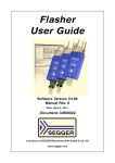
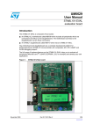
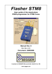
1
Flasher STM8
Software
User & Reference Guide
Document: UM05007
Software version: 1.30
Revision: 0
Date: July 24, 2014
A product of SEGGER Microcontroller GmbH & Co. KG
www.segger.com
2
Disclaimer
Specifications written in this document are believed to be accurate, but are not guaranteed to be entirely free of error. The information in this manual is subject to
change for functional or performance improvements without notice. Please make sure
your manual is the latest edition. While the information herein is assumed to be
accurate, SEGGER Microcontroller GmbH & Co. KG (the manufacturer) assumes no
responsibility for any errors or omissions. The manufacturer makes and you receive
no warranties or conditions, express, implied, statutory or in any communication with
you. The manufacturer specifically disclaims any implied warranty of merchantability
or fitness for a particular purpose.
Copyright notice
You may not extract portions of this manual or modify the PDF file in any way without
the prior written permission of the manufacturer. The software described in this document is furnished under a license and may only be used or copied in accordance
with the terms of such a license.
© 2009 - 2014 SEGGER Microcontroller GmbH & Co. KG, Hilden / Germany
Trademarks
Names mentioned in this manual may be trademarks of their respective companies.
Brand and product names are trademarks or registered trademarks of their respective holders.
Contact address
SEGGER Microcontroller GmbH & Co. KG
In den Weiden 11
D-40721 Hilden
Germany
Tel.+49 2103-2878-0
Fax.+49 2103-2878-28
Email: [email protected]
Internet: http://www.segger.com
Flasher STM8 Software (UM05007)
© 2009 - 2014 SEGGER Microcontroller GmbH & Co. KG
3
Manual versions
This manual describes the latest software version. If any error occurs, please inform
us and we will try to assist you as soon as possible.
Contact us for further information on topics or routines not yet specified.
Print date: July 24, 2014
Software
Revision
Date
1.30
0
140724
Flasher STM8 Software (UM05007)
By
Description
MC Initial version.
© 2009 - 2014 SEGGER Microcontroller GmbH & Co. KG
4
Flasher STM8 Software (UM05007)
© 2009 - 2014 SEGGER Microcontroller GmbH & Co. KG
5
About this document
Assumptions
This document assumes that you already have a solid knowledge of the following:
•
•
The target processor
DOS command line.
How to use this manual
This manual explains all the functions that Flasher STM8 Software offers.
Typographic conventions for syntax
This manual uses the following typographic conventions:
Style
Used for
Body
Body text.
Keyword
Text that you enter at the command-prompt or that appears on the
display (that is system functions, file- or pathnames).
Parameter
Parameters in API functions.
Sample
Sample code in program examples.
Reference
Reference to chapters, tables and figures or other documents.
GUIElement
Buttons, dialog boxes, menu names, menu commands.
Emphasis
Very important sections
Table 1.1: Typographic conventions
Flasher STM8 Software (UM05007)
© 2009 - 2014 SEGGER Microcontroller GmbH & Co. KG
6
SEGGER Microcontroller GmbH & Co. KG develops
and distributes software development tools and ANSI
C software components (middleware) for embedded
systems in several industries such as telecom, medical technology, consumer electronics, automotive
industry and industrial automation.
SEGGER’s intention is to cut software developmenttime for embedded applications by offering compact flexible and easy to use middleware,
allowing developers to concentrate on their application.
Our most popular products are emWin, a universal graphic software package for embedded applications, and embOS, a small yet efficent real-time kernel. emWin, written
entirely in ANSI C, can easily be used on any CPU and most any display. It is complemented by the available PC tools: Bitmap Converter, Font Converter, Simulator and
Viewer. embOS supports most 8/16/32-bit CPUs. Its small memory footprint makes it
suitable for single-chip applications.
Apart from its main focus on software tools, SEGGER developes and produces programming tools for flash microcontrollers, as well as J-Link, a JTAG emulator to assist in development, debugging and production, which has rapidly become the industry standard for
debug access to ARM cores.
Corporate Office:
http://www.segger.com
EMBEDDED SOFTWARE
(Middleware)
United States Office:
http://www.segger-us.com
SEGGER TOOLS
emWin
Flasher
Graphics software and GUI
emWin is designed to provide an efficient, processor- and display controller-independent graphical user
interface (GUI) for any application that
operates with a graphical display.
Starterkits, eval- and trial-versions are
available.
Flash programmer
Flash Programming tool primarily for microcontrollers.
J-Link
embOS
JTAG emulator with trace
USB driven JTAG interface for ARM cores with
Trace memory. supporting the ARM ETM (Embedded Trace Macrocell).
Real Time Operating System
embOS is an RTOS designed to offer
the benefits of a complete multitasking
system for hard real time applications
with minimal resources. The profiling
PC tool embOSView is included.
emFile
File system
emFile is an embedded file system with
FAT12, FAT16 and FAT32 support.
emFile has been optimized for minimum memory consumption in RAM and
ROM while maintaining high speed.
Various Device drivers, e.g. for NAND
and NOR flashes, SD/MMC and CompactFlash cards, are available.
JTAG emulator for ARM cores
USB driven JTAG interface for ARM cores.
J-Trace
J-Link / J-Trace Related Software
Add-on software to be used with SEGGER’s industry standard JTAG emulator, this includes flash
programming software and flash breakpoints.
Table 1.1:
emUSB
USB device stack
A USB stack designed to work on any
embedded system with a USB client
controller. Bulk communication and
most standard device classes are supported.
Flasher STM8 Software (UM05007)
© 2009 - 2014 SEGGER Microcontroller GmbH & Co. KG
7
Table of Contents
1 Introduction ......................................................................................................................9
1.1
1.1.1
1.2
1.3
1.3.1
1.3.2
What is Flasher STM8 Software? ................................................................ 10
Features................................................................................................. 10
Assumptions ........................................................................................... 11
Requirements.......................................................................................... 12
Host ...................................................................................................... 12
Target.................................................................................................... 12
2 Getting Started...............................................................................................................13
2.1
2.1.1
2.2
2.2.1
2.3
Setup..................................................................................................... 14
What is included? .................................................................................... 14
Using Flasher STM8 Software for the first time............................................. 15
Sample Projects ...................................................................................... 16
Menu structure........................................................................................ 17
3 Settings ..........................................................................................................................21
3.1
3.1.1
3.1.1.1
3.1.1.2
3.1.2
3.1.3
3.1.3.1
3.1.3.2
3.1.4
3.1.4.1
3.1.4.2
3.1.4.3
3.1.5
3.1.5.1
3.1.5.2
3.2
3.2.1
3.2.1.1
3.2.1.2
3.2.1.3
3.2.1.4
3.2.2
3.2.2.1
3.2.2.2
3.2.3
3.2.3.1
Project Settings....................................................................................... 22
General Settings...................................................................................... 22
TCP/IP ................................................................................................... 23
Enable Flasher logfile ............................................................................... 23
Target Interface Settings .......................................................................... 24
CPU Settings........................................................................................... 25
Device ................................................................................................... 25
Use target RAM ....................................................................................... 25
Flash Settings ......................................................................................... 26
Base Address .......................................................................................... 26
Organization ........................................................................................... 26
Sector selection....................................................................................... 26
Production settings .................................................................................. 27
Program serial number ............................................................................. 27
Actions performed by "Auto" ..................................................................... 30
Global Settings........................................................................................ 31
Operation ............................................................................................... 31
Disconnect after each operation................................................................. 31
Automatically unlock sectors ..................................................................... 31
Perform blank check ................................................................................ 31
Skip blank areas on read .......................................................................... 31
Logging .................................................................................................. 32
General log level ..................................................................................... 32
Enable DLL logfile .................................................................................... 32
Projects.................................................................................................. 33
Save project file on close .......................................................................... 33
4 Command Line Interface................................................................................................35
4.1
4.2
4.3
Overview ................................................................................................ 36
Command line options.............................................................................. 37
Batch processing ..................................................................................... 38
5 Working with Flasher STM8 software ............................................................................39
Flasher STM8 Software (UM05007)
© 2009 - 2014 SEGGER Microcontroller GmbH & Co. KG
8
5.1
5.2
5.2.1
5.2.2
Creating a new Flasher STM8 Software project ............................................ 40
Programming STM8 option bytes ............................................................... 45
Modifying option bytes already present ...................................................... 45
Creating option byte values for your target ................................................. 45
6 Target systems ..............................................................................................................47
6.1
Which devices can be programmed by Flasher STM8 Software? ..................... 48
7 Support ..........................................................................................................................49
7.1
7.1.1
7.1.2
7.2
Troubleshooting ...................................................................................... 50
General procedure................................................................................... 50
Typical problems ..................................................................................... 50
Contacting support .................................................................................. 51
8 Literature and references...............................................................................................53
Flasher STM8 Software (UM05007)
© 2009 - 2014 SEGGER Microcontroller GmbH & Co. KG
9
Chapter 1
Introduction
The following chapter introduces Flasher STM8 Software, highlights some of its
features, and lists its requirements on host and target systems.
Flasher STM8 Software (UM05007)
© 2009 - 2014 SEGGER Microcontroller GmbH & Co. KG
10
CHAPTER 1
1.1
Introduction
What is Flasher STM8 Software?
Flasher STM8 Software is a stand-alone flash programming software for PCs running
Microsoft Windows. The following Microsoft Windows versions are supported:
•
•
•
•
•
•
•
•
•
•
Microsoft
Microsoft
Microsoft
Microsoft
Microsoft
Microsoft
Microsoft
Microsoft
Microsoft
Microsoft
Windows
Windows
Windows
Windows
Windows
Windows
Windows
Windows
Windows
Windows
2000
XP
XP x64
2003
2003 x64
Vista
Vista x64
7
7 x64
8
Flasher STM8 Software has an intuitive user interface and makes programming flash
devices convenient. Flasher STM8 Software requires a Flasher STM8, flasher for
STM8 cores, to interface to the hardware. Flasher STM8 Software supports a feature
called smart read back, which only transfers non-blank portions of the flash, increasing the speed of read back greatly. These features along with its ability to work with
any STM8 chip makes it a great solution for most projects.
1.1.1
•
•
•
•
•
•
Features
Any STM8 core supported.
STM8 microcontroller (internal flash) support.
Smart read back: only non-blank portions of flash are transferred and saved.
Verbose logging of all communication.
.hex, .mot, .srec, and .bin support.
Intuitive user interface.
Flasher STM8 Software (UM05007)
© 2009 - 2014 SEGGER Microcontroller GmbH & Co. KG
11
1.2
Assumptions
This user manual assumes that you already possess working knowledge of the
Flasher STM8 device. If you feel that your knowledge of Flasher STM8 is not
sufficient, we recommend the Flasher STM8 manual, which describes the device and
its use in detail.
Flasher STM8 Software (UM05007)
© 2009 - 2014 SEGGER Microcontroller GmbH & Co. KG
12
CHAPTER 1
1.3
Introduction
Requirements
1.3.1
Host
Flasher STM8 Software requires a PC running Microsoft Windows 2000 or later with a
free USB port dedicated for a Flasher STM8. A network connection is required only if
you want to use Flasher STM8 Software together with a remote Flasher STM8 device.
When using a network connection for communication with the Flasher no USB data
connection is required. USB will be needed for power only.
1.3.2
Target
A SWIM interface must be available on the target device to establish the connection
with the host system.
The target has to be either be powered externally or being able to be powered by 5V
that can optionally be output from the Flasher itself.
Flasher STM8 Software (UM05007)
© 2009 - 2014 SEGGER Microcontroller GmbH & Co. KG
13
Chapter 2
Getting Started
This chapter presents an introduction to Flasher STM8 Software. It provides an
overview of the included sample projects and describes Flasher STM8 Software’s
menu structure in detail.
Flasher STM8 Software (UM05007)
© 2009 - 2014 SEGGER Microcontroller GmbH & Co. KG
14
CHAPTER 2
2.1
Getting Started
Setup
The Flasher STM8 setup procedure required in order to work with Flasher STM8 Software is described in the Flasher STM8 User Guide. The Flasher STM8 User Guide is
part of the Flasher STM8 software package which is available for download under
www.segger.com.
2.1.1
What is included?
The following table shows the contents of all subdirectories of the Flasher STM8
software and documentation pack with regard to Flasher STM8 Software:
Directory
Contents
.
The Flasher STM8 Software application. Please refer to
the Flasher STM8 manual for more information about
the other Flasher related tools.
.\Doc
Contains the Flasher STM8 Software documentation and
the other Flasher related manuals.
.\ETC\FlasherSTM8\
Two *.csv files for the Flasher STM8 Software internal
management of supported MCU’s und flash chips.
.\Sample\FlasherSTM8\ProjectFiles\
Contains sample projects with good default settings
(see section Sample Projects on page 16 for further
details).
Table 2.1: Flasher STM8 Software directory structure
Flasher STM8 Software (UM05007)
© 2009 - 2014 SEGGER Microcontroller GmbH & Co. KG
15
2.2
Using Flasher STM8 Software for the first time
Start Flasher STM8 Software from the Windows Start menu. Flasher STM8 Software’s
main window will appear, which contains a log window at the bottom and the
Project window of a default project on the left. The application log will initially
display:
•
•
•
•
•
The
The
The
The
The
version and time of compilation for the Flasher STM8 Software application.
version and time of compilation for the STM8 DLL.
number of supported flash devices.
number of supported MCU devices.
location of the default project.
The Project window contains an overview of the current project settings (initially
Flasher STM8 Software opens a default project).
Flasher STM8 Software (UM05007)
© 2009 - 2014 SEGGER Microcontroller GmbH & Co. KG
16
CHAPTER 2
2.2.1
Getting Started
Sample Projects
If you are new to Flasher STM8 Software, it might be a good idea to open one of our
sample projects to familiarize yourself with the application. You find those project
files in the Projects subdirectory of Flasher STM8 Software’s installation directory.
Once you have opened a project file, the project window contains the relevant project
settings, e.g. chip type, RAM size etc. The settings are known to be good defaults for
the respective devices. You may then continue to open your own data files to actually
program your device. The table below contains the included project files together
with a short description.
Project
STM8L101K3.jflash
STM8S208MB.jflash
Description
STM8L101K3 with internal flash memory
STM8S208MB with internal flash memory
Table 2.2: List of sample Flasher STM8 Software projects
Flasher STM8 Software (UM05007)
© 2009 - 2014 SEGGER Microcontroller GmbH & Co. KG
17
2.3
Menu structure
The main window of Flasher STM8 Software contains seven drop-down menus (File,
Edit, View, Target, Options, Window, Help). Any option within these drop-down
menus that is followed by a three period ellipsis (...), is an option that requires more
information before proceeding.
Flasher STM8 Software (UM05007)
© 2009 - 2014 SEGGER Microcontroller GmbH & Co. KG
18
CHAPTER 2
Getting Started
File menu elements
Command
Description
Opens a data file that may be used to flash the target
device. The data file must be an Intel HEX file, a Motorola
S file, or a Binary file (.hex, .mot, .srec, or .bin).
Merge
Merges two data files (.hex, .mot, .srec, or .bin).
Save
Saves the data file that currently has focus.
Saves the data file that currently has focus using the
Save As...
name and location given.
New Project
Creates a new project using the default settings.
Opens a Flasher STM8 Software project file. Note that
Open Project...
only one project file may be open at a time. Opening a
project will close any other project currently open.
Save Project
Saves a Flasher STM8 Software project file.
Saves a Flasher STM8 Software project file using the
Save Project As...
name and location given.
Close Project
Closes a Flasher STM8 Software project file.
Saves a Flasher STM8 Software configuration as proSave programmer congrammer configuration file using the name and location
figuration file...
given.
Save programmer data Saves the content of the memory window as programmer
file...
data image file using the name and location given.
Download config &
Download configuration and data to program to a condata file to programnected programmer for stand alone usage.
mer
Download serial num- Download serial number file to program to a connected
ber file to programmer programmer for stand alone usage.
Recent Files >
Contains a list of the most recently open data files.
Recent Projects >
Contains a list of the most recently open project files.
Exit
Exits the Flasher STM8 Software application.
Open...
Table 2.3: File menu elements
Edit menu elements
Command
Relocate...
Delete range...
Description
Relocates the start of the data file to the supplied hex
offset from the current start location.
Deletes a range of values from the data file, starting and
ending at given addresses. The End address must be
greater than the Start address otherwise nothing will be
done.
Table 2.4: Edit menu elements
View menu elements
Command
Log
Project
Description
Opens and/or brings the log window to the active window.
Opens and/or brings the project window to the active
window.
Table 2.5: View menu elements
Flasher STM8 Software (UM05007)
© 2009 - 2014 SEGGER Microcontroller GmbH & Co. KG
19
Target menu elements
Command
Connect
Disconnect
Test >
Secure chip
Unsecure chip
Check blank
Fill with zero
Erase sectors
Erase chip
Program
Program & Verify
Auto
Verify
VerifyCRC >
Read back >
Start Application
Description
Creates a connection through the Flasher using the configuration options set in the Project settings... of the
Options drop-down menu.
Disconnects a current connection that has been made
through the Flasher.
Two test functions are implemented "Generates test
data" generates data which can be used to test if the
flash can be programmed correctly. The size of the generated data file can be defined.
"Test speed..." writes data of a specified size to a defined
address, reads the written data back and measures the
up- and download speed.
"Hardware >" allows testing of proper functionality of the
Flasher RS232 interface signals.
Secures the MCU.
Unsecures the MCU.
Checks flash to see if it is empty.
Fills all selected flash sectors with zero.
Erases all selected flash sectors.
Erases the entire chip.
Programs the chip using the currently active data file.
Programs the chip using the currently active data file and
then verifies that it was written successfully.
The Auto command performs a sequence of steps. It connects to the device, erases sectors and programs the chip
using the currently active data file before the written
data is finally verified. The range of sectors to be erased
can be configured through the Flash tab of the Project
settings dialog and through the Global settings dialog.
See chapter Settings on page 21 for further details.
Verifies the data found on the chip with the data file.
Verifies the CRC. There are three ways in which the CRC
can be verified.
"Affected sectors" verifies the CRC of the affected sectors.
"Selected sectors" verifies the CRC of the selected sectors.
"Entire chip" verifies the CRC of the entire chip.
Reads back the data found on the chip and creates a new
data file to store this information. There are three ways
in which the data can be read back. The Selected sectors
identified on the Flash tab of the Project Settings... found
in the Options drop-down menu may be read back. The
Entire chip may be read back. A specified Range... may
be read back.
Starts the application found on the chip.
Table 2.6: Target menu elements
Flasher STM8 Software (UM05007)
© 2009 - 2014 SEGGER Microcontroller GmbH & Co. KG
20
CHAPTER 2
Getting Started
Options menu elements
Command
Project settings...
Global settings...
Description
Location of the project settings that are displayed in the
snapshot view found in the Project window of the Flasher
STM8 Software application as well as various settings
needed to locate the Flasher and pass specified commands needed for chip initialization.
Settings that influence the general operation of Flasher
STM8 Software.
Table 2.7: Options menu elements
Window menu elements
Command
Cascade
Tile Horizontal
Tile Vertical
Description
Arranges all open windows, one above the other, with the
active window at the top.
Tiles the windows horizontally with the active window at
the top.
Tiles the windows vertically with the active window at the
left.
Table 2.8: Window menu elements
Help menu elements
Command
Description
Flasher STM8 Software
User’s Guide
Flasher STM8 User’s
Guide
Shows this help file in a PDF viewer such as Adobe
Reader.
Shows the Flasher STM8 User’s Guide in a PDF viewer
such as Adobe Reader.
Shows a dialog with licensing information. The serial
number of a connected Flasher may be read and licenses
added or removed.
Flasher STM8 Software and company information.
Licenses...
About...
Table 2.9: Help menu elements
Flasher STM8 Software (UM05007)
© 2009 - 2014 SEGGER Microcontroller GmbH & Co. KG
21
Chapter 3
Settings
The following chapter provides an overview of the program settings. Both, general
and per project settings are considered.
Flasher STM8 Software (UM05007)
© 2009 - 2014 SEGGER Microcontroller GmbH & Co. KG
22
CHAPTER 3
3.1
Settings
Project Settings
Project settings are available from the Options menu in the main window or by using
the ALT-F7 keyboard shortcut.
3.1.1
General Settings
This dialog is used to choose the connection to the Flasher STM8. The Flasher can
either be connected directly over USB to the host system, or it can be connected
through TCP/IP remotely. Refer to the Flasher STM8 manual for more information
regarding the operation of Flasher STM8
The complexity of the user interface can be selected. Select the Engineering
checkbox if you want to setup your project or the Simplified checkbox if you use
Flasher STM8 Software in production environments. In the simplified user interface
some options are disabled to decrease possible error sources in the production
phase.
Flasher STM8 Software (UM05007)
© 2009 - 2014 SEGGER Microcontroller GmbH & Co. KG
23
3.1.1.1 USB
If this option is checked, Flasher STM8 Software will connect to Flasher over the USB
port. You may change the device number if you want to connect more than one
Flasher to your PC. The default device number is 0. For more information about how
to use multiple Flasher on one PC, please refer to the Flasher STM8 User Guide.
3.1.1.2 TCP/IP
If this option is checked, Flasher STM8 Software will connect to Flasher via TCP/IP.
You have to specify the IP address of the Flasher you want to connect to.
3.1.1.3 Enable Flasher logfile
If this option is checked, you can specify a file name for the Flasher STM8 Software
logfile. The Flasher logfile will contain the same outputs as the Flasher STM8 Software log window. You can specify one logfile per project.
Flasher STM8 Software (UM05007)
© 2009 - 2014 SEGGER Microcontroller GmbH & Co. KG
24
CHAPTER 3
3.1.2
Settings
Target Interface Settings
This dialog is used to configure the target interface.
At the moment Flasher STM8 is able to choose between the target interfaces SWIM
(high speed) which is the default and should be used in almost any case and SWIM
(low speed) which is slower than the high speed interface but might help if Flasher
STM8 is not operating stable within your environment.
Further details about the bit format used in high speed and low speed interface mode
can be acquired from the STM8 SWIM protocol available from ST.
Flasher STM8 Software (UM05007)
© 2009 - 2014 SEGGER Microcontroller GmbH & Co. KG
25
3.1.3
CPU Settings
This dialog allows the selection of microcontroller dependent settings.
To program internal flash devices choose the respective microcontroller in the
Device list. If your microcontroller is not found on this list, contact SEGGER as new
microcontrollers are continuously being added.
3.1.3.1 Device
Select the respective microcontroller from the list to program internal flash devices.
3.1.3.2 Use target RAM
You may enable the use of target RAM to speed up flash operations. To use the target
RAM, a start location in RAM and the amount of RAM to be used must be entered.
Flasher STM8 Software (UM05007)
© 2009 - 2014 SEGGER Microcontroller GmbH & Co. KG
26
CHAPTER 3
3.1.4
Settings
Flash Settings
This dialog is used to select and configure the flash device to operate with. The listed
options of the Flash settings menu are dependent on the selection in the CPU
settings dialog.
The menu should look similar to the screenshot below.
3.1.4.1 Base Address
You may enter the base address of the selected flash memory. The default value is 0,
which fits for all STM8 devices.
3.1.4.2 Organization
You should select the buswidth and the number of flash chips connected to the
address and data bus of the MCU.
Normally, this has not to be changed for STM8 devices.
3.1.4.3 Sector selection
The final section of this dialog indicates the sectors to be acted upon, whether they
are to be cleared, read back, or written. An individual or series of sectors may be
selected from the predetermined valid range.
Flasher STM8 Software (UM05007)
© 2009 - 2014 SEGGER Microcontroller GmbH & Co. KG
27
3.1.5
Production settings
The performed actions of the auto programming feature (Target -> Auto, shortcut:
F7) can be defined in the production settings dialog. The default behaviour is Program and Verify Complete data.
3.1.5.1 Program serial number
Flasher STM8 supports programming of serial numbers. In order to use the serial
number programming feature, the project to be used as well as some files in the
working folder (depending on the configuration) need to be configured first.
In general, Flasher STM8 supports two ways of programming a serial number into the
target:
1.
2.
Programming continuous serial numbers. Serial number is 1-4 bytes in size. The serial
number to start with, serial number increments, the size of serial numbers and the
chosen address have to be configured.
Programming custom serial numbers from a serial number list file. The line of the
list file to start with, the line increment, the size of serial numbers and the chosen address have to be configured. Also, a serial number list file needs to be created by user.
In the following, some generic information on how to setup a serial number programming configuration are given.
Flasher STM8 Software (UM05007)
© 2009 - 2014 SEGGER Microcontroller GmbH & Co. KG
28
CHAPTER 3
Settings
3.1.5.1.1 Serial number settings
In order to use the serial number feature, the Flasher STM8 project has to be configured to enable programming a serial number at a specific address. This is done by
enabling the Program serial number option.
Setting
Address
Len
Meaning
The address the serial number should be
programmed at.
The length of the serial number (in
bytes) which should be programmed.
If no serial number list file is given,
Flasher STM8 allows to use a 1-4 byte
serial number. In case of 8 is selected as
length, the serial number and its complementary is programmed at the given
address.
In case a serial number list file is given,
Flasher STM8 will take the serial number
bytes from the list file. If a serial number
in the list file does not define all bytes of
Len, the remaining bytes are filled with
0s. No complements etc. are added to
the serial number.
In case no serial number list file is given,
Next SN is the next serial number which
should be programmed.
The serial number is always stored in big
endian format in the flash memory.
Next SN
Increment
In case a serial number list file is given,
Next SN describes the line of the serial
number list file where to read the next
serial number bytes from. Flasher STM8
starts counting with line 0, so in order to
start serial number programming with
the first line of the SNList.txt, Next SN
needs to be set to 0.
Specifies how much Next SN is incremented.
Table 3.1: Flasher STM8 serial number settings
3.1.5.1.2 Serial number file
When programming continuous serial numbers, upon starting the program process
Target -> Auto the Flasher STM8 software will automatically create a file named
<ProjectName>_Serial.txt at the software’s working folder. This file contains the
value defined by the Next SN option in the Flasher STM8 settings. The file can also be
edited manually by the user, as the serial number is written to it in ASCII.
3.1.5.1.3 Serial number list file
In order to program serial numbers that can not be covered by the continuous serial
number scheme above (e.g. when programming non-continuous serial numbers or
having gaps between serial numbers), a serial number list file needs to be created
manually by the user. When selecting Target -> Auto, the Flasher STM8 software
will then check its working folder for a serial number list file named <ProjectName>_SNList.txt.
Flasher STM8 Software (UM05007)
© 2009 - 2014 SEGGER Microcontroller GmbH & Co. KG
29
The serial number list file needs to adhere to the following syntax:
•
•
One serial number per line
Each byte of the serial number is described by two hexadecimal digits.
Example
An 8-byte serial number should be programmed at address 0x08000000 and read in
the memory as follows:
0x08000000: 0x01 0x02 0x03 0x04 0x55 0x66 0x77 0x88
To do so, the serial number list file should look as follows:
The number of bytes to read per line is configured via the Len option in the settings
menu.
The line the Flasher STM8 software has to program in the first programming cycle is
configured via the Next SN option in the settings menu. In this case, Next SN needs
to be set to 0, since programming should start with the serial number bytes defined
in the first line of the file.
Note:
If the number of bytes specified in a line of the serial number list file is
less than the serial number length defined in the project, the remaining bytes are
filled with 0s.
Note:
If the number of bytes specified in a line of the serial number list file is
greater than the serial number length defined in the Flasher project, the remaining
bytes will be ignored.
Note:
When using Windows 7, please make sure that the used project file is
located at a folder with write permission.
3.1.5.1.4 Programming process
Flasher STM8 will increment the serial number in <ProjectName>_Serial.txt by the
value defined in Increment after each successful programming cycle.
3.1.5.1.5 Sample setup
The following is a small sample to demonstrate the setup of the Flasher STM8 software for serial number programming. In this sample, 4-byte serial numbers starting
at 1234567 shall be programmed at address 0x08001000.
Defining serial number address, length, start value and increment
In the Flasher project the following values need to be defined:
Flasher STM8 Software (UM05007)
© 2009 - 2014 SEGGER Microcontroller GmbH & Co. KG
30
CHAPTER 3
•
•
•
•
Settings
Address is 0x08001000
Len is 4
Next SN is 1234567
Increment is 1
Now Flasher STM8 is prepared to program the serial number.
After programming the serial number, the <ProjectName>_Serial.txt file is created within the folder of the Flasher project file.
3.1.5.2 Actions performed by "Auto"
The checked options will be perforemed when auto programming a target (Target ->
Auto, shortcut: F7). The default behaviour is Program and Verify CRC. You can
optionally include Erase, Unsecure Chip and Start application. Find below a table
which describes the commands:
Command
Description
Performs an erase depending on the settings, selected in the
drop down box.
Erase
•
Chip: Erase the entire chip independent of the content.
Program
Programs the data file.
Verifies the program data.
Verify
•
Complete data: Verifies data by reading it back.
Unsecure chip
Unsecures the device if supported by algorithm
Starts application after programming/verify completed. Needs
Start application
reset pin to be connected to Flasher STM8.
Table 3.2: Actions performed by "Auto"
Flasher STM8 Software (UM05007)
© 2009 - 2014 SEGGER Microcontroller GmbH & Co. KG
31
3.2
Global Settings
Global settings are available from the Options menu in the main window.
3.2.1
Operation
You may define the behavior of some operations such as "Auto" or "Program & Verify".
3.2.1.1 Disconnect after each operation
If this option is checked, connection to the target will be closed at the end of each
operation.
3.2.1.2 Automatically unlock sectors
If this option is checked, all sectors affected by an erase or program operation will be
automatically unlocked if necessary.
3.2.1.3 Perform blank check
If this option is checked, a blank check is performed before any program operation to
check if the affected flash sectors are completely empty. The user will be asked to
erase the affected sectors if they are not empty.
3.2.1.4 Skip blank areas on read
If this option is checked, a blank check is performed before any read back operation
to check which flash areas need to be read back from target. This improves performance of read back operations since it minimizes the amount of data to be transferred via SWIM and USB or ethernet.
Flasher STM8 Software (UM05007)
© 2009 - 2014 SEGGER Microcontroller GmbH & Co. KG
32
CHAPTER 3
3.2.2
Settings
Logging
You may set some logging options to customize the log output of Flasher STM8 software.
3.2.2.1 General log level
This specifies the log level of Flasher STM8 Software. Increasing log levels result in
more information logged in the log window.
3.2.2.2 Enable DLL logfile
If this option is checked, you can specify a file name for the DLL logfile. The DLL logfile differs from the log window output of Flasher STM8 Software. It does not log
Flasher STM8 Software operations performed. Instead of that, it logs the STM8 DLL
API functions called from within Flasher STM8 Software only.
Flasher STM8 Software (UM05007)
© 2009 - 2014 SEGGER Microcontroller GmbH & Co. KG
33
3.2.3
Projects
You may define whether changes to a project should be saved automatically.
3.2.3.1 Save project file on close
If this option is checked, the Flasher STM8 Software will automatically save project
changes (including firmware files) when closing the software. If the option is not
checked, but the Flasher STM8 Software detects changes to the project upon closing,
a dialog will ask whether these changes should be saved. When using the Flasher
STM8 Software via command line, the dialog will not appear and changes will only be
saved if the option was checked.
Flasher STM8 Software (UM05007)
© 2009 - 2014 SEGGER Microcontroller GmbH & Co. KG
34
Flasher STM8 Software (UM05007)
CHAPTER 3
Settings
© 2009 - 2014 SEGGER Microcontroller GmbH & Co. KG
35
Chapter 4
Command Line Interface
This chapter describes the Flasher STM8 Software command line interface. The
command line allows using Flasher STM8 Software in batch processing mode and
other advanced uses.
Flasher STM8 Software (UM05007)
© 2009 - 2014 SEGGER Microcontroller GmbH & Co. KG
36
4.1
CHAPTER 4
Command Line Interface
Overview
In addition to its traditional Windows graphical user interface (GUI), Flasher STM8
Software supports a command line mode as well. This makes it possible to use
Flasher STM8 Software for batch processing purposes. All important options accessible from the menus are available in command line mode as well. If you provide command line options, Flasher STM8 Software will still start its GUI, but processing will
start immediately.
The screenshot below shows the command line help dialog, which is displayed if you
start Flasher STM8 Software in a console window with FlasherSTM8.exe -help or
FlasherSTM8.exe -?
Flasher STM8 Software (UM05007)
© 2009 - 2014 SEGGER Microcontroller GmbH & Co. KG
37
4.2
Command line options
This section lists and describes all available command line options. Some options
accept additional parameters which are enclosed in angle brackets, e.g. <FILENAME>. If these parameters are optional they are enclosed in square brackets too,
e.g. [<SADDR>]. Neither the angel nor the square brackets must be typed on the
command line, they are used here only to denote (optional) parameters. Also, note
that a parameter must follow immediately after the option, e.g. FlasherSTM8.exe openprjC:\Projects\Default.jflash.
All command line options return 0 if the processing was successfully. An return value
unequal 0 means that an error occured.
Option
-openprj<FILENAME>
-merge<FILENAME>[,SADDR]
-saveprjas<FILENAME>
-saveprj
-open<FILENAME>[,<SADDR>]
-saveas<FILENAME>[,<SADDR>,<EADDR>]
-save[<SADDR>,<EADDR>]
-savecfg<FILENAME>
-savedat<FILENAME>
-download
-relocate<OFFSET>
-delrange<SADDR>,<EADDR>
-connect
-disconnect
-unsecurechip
-checkblank
-erasesectors
-erasechip
-programverify
-program
-auto
-verify
-readsectors
-readchip
-readrange<SADDR>,<EADDR>
-startapp
-exit
-help
-?
Description
Open an existing project file.
Merges the currently opened datafile with
another data file (.hex, .mot, .srec, or .bin).
In case of .bin a second parameter in hex is
needed as start addr.
Save the current project in the specified file.
Save the current project.
Open a data file. Please note that the
<SADDR> parameter applies only if the data
file is a *.bin file.
Save the current data file into the specified
file. Please note that the parameters
<SADDR>, <EADDR> apply only if the data file
is a *.bin file or *.c file.
Save the current data file. Please note that the
parameters <SADDR>,<EADDR> apply only if
the data file is a *.bin file or *.c file.
Saves programmer config file.
Saves programmer data file.
Downloads configuration to programmer.
Relocate data by the given offset.
Delete data in the given range.
Connect to target.
Disconnect from target.
Unsecures target device.
Blank check target.
Erases selected sectors.
Erases entire flash chip.
Program and verify target.
Program target.
Erases, programs and verifies target.
Verify target memory.
Read selected sectors.
Read entire flash chip.
Read specified range of target memory.
Start target application.
Exit Flasher STM8 Software.
Display help dialog.
Display help dialog.
Table 4.1: Flasher STM8 Software command line options
Flasher STM8 Software (UM05007)
© 2009 - 2014 SEGGER Microcontroller GmbH & Co. KG
38
4.3
CHAPTER 4
Command Line Interface
Batch processing
Flasher STM8 Software can be used for batch processing purposes. All important
options are available in command line mode as well. If you provide command line
options, Flasher STM8 Software will still start its GUI, but processing will start immediately.
The example batchfile displays a message, opens a project and a data file, starts programming and closes Flasher STM8 Software. The return value will be checked and in
case of an error an error message displayed.
Adapt the example according to the requirements of your project.
@ECHO OFF
ECHO Open a project and data file, start programming and exit
FlasherSTM8.exe -openprjC:\Projects\Default.jflash -openC:\Data\data.bin,0x4800 program -exit
IF ERRORLEVEL 1 goto ERROR
goto END
:ERROR
ECHO Flasher STM8 Software:
pause
Error!
:END
Note, that every call of FlasherSTM8.exe has to be completed with the -exit option,
otherwise the execution of the batch file stops and the following commands will not
be processed.
Flasher STM8 Software (UM05007)
© 2009 - 2014 SEGGER Microcontroller GmbH & Co. KG
39
Chapter 5
Working with Flasher STM8
software
This chapter contains information about the required steps how to setup a new
Flasher STM8 Software project and other common tasks related to the Flasher STM8
software that you may need when working with the Flasher STM8.
Flasher STM8 Software (UM05007)
© 2009 - 2014 SEGGER Microcontroller GmbH & Co. KG
40
CHAPTER 5
5.1
Working with Flasher STM8 software
Creating a new Flasher STM8 Software project
Before creating a new Flasher STM8 Software project, you should have an understanding of your target system:
•
•
Take a look at the schematic and the documentation of your CPU / SOC.
Locate RAM in the chip documentation.
In the following all the necessary steps to create a project file, are explained.
1.
2.
Select File -> New Project to open a new project.
Open the Project Settings context menu. Select Options -> Project Settings
or press ALT-F7 to open the Project settings dialog and select the type of connection to Flasher STM8.
Select Engineering (More options, typically used for setup).
Flasher STM8 Software (UM05007)
© 2009 - 2014 SEGGER Microcontroller GmbH & Co. KG
41
3.
The Target interface dialog should look similar to the one below. Using the SWIM
(high speed) interface should be fine in almost any case. If you are using a
longer target cable than shipped with your Flasher STM8 operation in high speed
mode can not be guaranteed. If your Flasher is operating unstable or is not able
to communicate with the target at all it might help to use the low speed mode
instead.
Flasher STM8 Software (UM05007)
© 2009 - 2014 SEGGER Microcontroller GmbH & Co. KG
42
CHAPTER 5
4.
Working with Flasher STM8 software
Choose a device from Device choice-list in the CPU dialog. Flasher STM8 Software uses correct default values (RAM address and size) for this device. If your
device is not in the list you may have success in choosing a device which fits your
target system best.
Flasher STM8 Software (UM05007)
© 2009 - 2014 SEGGER Microcontroller GmbH & Co. KG
43
5.
The Flash dialog should look similar to the screenshot below. Normally, all default
settings can be used without modifications.
Flasher STM8 Software (UM05007)
© 2009 - 2014 SEGGER Microcontroller GmbH & Co. KG
44
CHAPTER 5
Working with Flasher STM8 software
6.
The Production dialog is secondary for a setup. You can define the behaviour of
the Auto option (Target -> Auto or shortcut: F7) which will affect the auto operation in Flasher stand alone mode.
7.
Save your project (File -> Save Project) and test it.
Flasher STM8 Software (UM05007)
© 2009 - 2014 SEGGER Microcontroller GmbH & Co. KG
45
5.2
Programming STM8 option bytes
For STM8 devices the option bytes are memory mapped to the addr. 0x4800 . For
Flasher STM8 software option bytes are handled the same way as any other programmable code/data area. The exact meaning of every option byte for your device can be
found in the device specific manual of your chip manufacturer.
5.2.1
Modifying option bytes already present
If the output of your program code already contains option bytes it is very easy to
modify them. Open your output with the Flasher STM8 Software and modify the
option byte values already present as needed.
5.2.2
Creating option byte values for your target
If for some reason you do not already have option bytes in your data file or you do
not have the option bytes available you need you can follow these steps to create the
desired option byte values:
•
•
•
•
Start the Flasher STM8 software
Open or create a project for your device
In the project settings on the "Flash" tab select only the sector located at 0x4800
from the sector list box
Use the menu entry "Target->Read back->Selected sectors" to read back the
sector that contains the option bytes.
You can now freely edit the option bytes and any other data stored in the option
bytes sector.
Flasher STM8 Software (UM05007)
© 2009 - 2014 SEGGER Microcontroller GmbH & Co. KG
46
Flasher STM8 Software (UM05007)
CHAPTER 5
Working with Flasher STM8 software
© 2009 - 2014 SEGGER Microcontroller GmbH & Co. KG
47
Chapter 6
Target systems
The following chapter contains information about the supported flash devices.
Flasher STM8 Software (UM05007)
© 2009 - 2014 SEGGER Microcontroller GmbH & Co. KG
48
CHAPTER 6
Target systems
6.1 Which devices can be programmed by Flasher
STM8 Software?
Flasher STM8 Software can program internal flash. Flasher STM8 Software supports
all STM8 microcontrollers. The only limitation in using a specific STM8 device is typically that it might not be known to the STM8 software yet.
A list of devices supported in the most recent version of the Flasher STM8 Software
can be found at the following location:
http://www.segger.com/flasher-stm8_supported_devices.html
If you need support for a chip or flash not supported yet, do not hesitate to contact
us. Segger is constantly adding support for new devices. You may want to request an
updated list or have a look at http://www.segger.com for more up to date information.
Flasher STM8 Software (UM05007)
© 2009 - 2014 SEGGER Microcontroller GmbH & Co. KG
49
Chapter 7
Support
The following chapter provides information about how to contact our support.
Flasher STM8 Software (UM05007)
© 2009 - 2014 SEGGER Microcontroller GmbH & Co. KG
50
CHAPTER 7
7.1
Support
Troubleshooting
7.1.1
•
•
•
7.1.2
General procedure
Make sure your Flasher is working as expected. See the troubleshooting section
in the Flasher manual.
Ensure that the target hardware matches the project file settings. Pay special
attention to the following aspects:
- RAM address
- Flash base address
- MCU
Try to program your target device using a sample project file if available. Flasher
STM8 Software ships with an extensive number of project files for many target
boards. See section Sample Projects on page 16 for a complete list of project
files.
Typical problems
Failed to connect
Meaning:
This error message is shown if any error occurs during the connection process.
Remedy:
Make sure the target is actually connected to Flasher STM8 and powered. Verify the
correct connection between target and Flasher.
Blank check failed
Meaning:
The target memory was not empty during blank check.
Remedy:
Erase target memory.
RAM check failed
Meaning:
No RAM found at the specified RAM location.
Remedy:
Make sure a correct RAM address is specified in the project settings. See section CPU
Settings on page 25.
Unsupported flash type / bus width
Meaning:
The target flash memory or the bus organization is not yet supported.
Remedy:
Inform us about the device you want to use. SEGGER is constantly adding support for
new devices.
No matching RAMCode
Meaning:
There is no programming algorithm available for the selected target memory type.
Remedy:
Inform us about the device you want to use. SEGGER is constantly adding support for
new devices.
Flasher STM8 Software (UM05007)
© 2009 - 2014 SEGGER Microcontroller GmbH & Co. KG
51
7.2
Contacting support
If you experience a Flasher STM8 Software related problem and the advices from the
sections above do not help you to solve it, you may contact our Flasher STM8 Software support. In this case, please provide us with the following information:
•
•
•
•
A detailed description of the problem.
The relevant log file and project file. In order to generate an expressive log file,
set the log level to "All messages" (see section Global Settings on page 31 for
information about changing the log level in Flasher STM8 Software).
The relevant data file as a .hex or .mot file (if possible)
The processor used
Once we received this information we will try our best to solve the problem for you.
Our contact address is as follows:
SEGGER Microcontroller GmbH & Co. KG
In den Weiden 11
D-40721 Hilden
Germany
Tel.+49 2103-2878-0
Fax.+49 2103-2878-28
Email: [email protected]
Internet: http://www.segger.com
Flasher STM8 Software (UM05007)
© 2009 - 2014 SEGGER Microcontroller GmbH & Co. KG
52
Flasher STM8 Software (UM05007)
CHAPTER 7
Support
© 2009 - 2014 SEGGER Microcontroller GmbH & Co. KG
53
Chapter 8
Literature and references
This chapter lists documents, which we think may be useful to gain a deeper understanding of technical details.
Flasher STM8 Software (UM05007)
© 2009 - 2014 SEGGER Microcontroller GmbH & Co. KG
54
CHAPTER 8
Reference
[STM8 SWIM
protocol]
Title
Literature and references
Comments
STM8 SWIM communication protocol and debug
module, UM0470
This document describes the SWIM
protocol used by STM8 targets for
communication with the Flasher
STM8. It is publicly available from
ST (www.st.com).
Table 8.1: Literature and References
Flasher STM8 Software (UM05007)
© 2009 - 2014 SEGGER Microcontroller GmbH & Co. KG
55
Index
F
Flasher ...............................................12
M
Menu structure ....................................17
P
Projects ..............................................16
S
SWIM .................................................12
Syntax, conventions used ...................... 5
T
TCP/IP ...............................................23
U
USB ...................................................23
Flasher STM8 Software (UM05007)
© 2009 - 2014 SEGGER Microcontroller GmbH & Co. KG
56
Flasher STM8 Software (UM05007)
CHAPTER
© 2009 - 2014 SEGGER Microcontroller GmbH & Co. KG