1
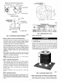
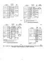
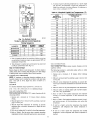
3/8 IN. DIA TIEDOWN "_
KNOCKOUTS IN BASEPAN
(2) PLACES
NOTE: Avoid contact between tubing and structure
OUTDOOR
WALL-k ,NDOOR
WALtz
?
CAULK (_
-- &-
LIQUID TUBE_
2/-%
J_'_
SULATION -_"
_
.........
VAPOR TUBE
THROUGH THE WALL
J_"-JOIST
HANGER STRAP'_
(AROUND VAPOR
TUBE ONLY)
%= -_,' \
/_
--8
3/16"
INSULATION
A97548
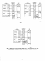
Dimensions (In.)
I1
UNIT
SIZE
tl
_---
MINIMUM MOUNTING
PAD DIMENSIONS
LIQUID TUBE
SUSPENSION
TIEDOWN KNOCKOUT
LOCATIONS
Support
Feet
Snow
Stand
018, 024
20 X 27
24 X 28
4-1/8
7-1/8
030-060
26 X 32
31 X 35
5-1/16
9-11/16
A
Fig. 3_Mounting
B
Unit to Pad
A94028
Fig. 2---Connecting
---) Step 2--Install
If conditions
down bolts
provided in
to determine
Step 5---Elevate Unit
Tubing Installation
on a Solid, Level Mounting
Pad
or local codes require the unit be attached to pad, tie
should be used and fastened through knockouts
unit base pan. Refer to unit mounting pattern in Fig. 3
base pan size and knockout hole location.
eqmpment
Elevate
On rooftop applications, mount on level platform or frame 6 in.
above roof surface. Place unit above a load-bearing wall and
isolate unit and tubing set from structure. Arrange supporting
members to adequately support unit and minimize transmission of
vibration to building. Consult local codes governing rooftop
applications.
damage.
unit per
clearance
above
drainage
of unit.
installed.
freezing
Use
local climate
estimated
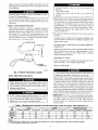
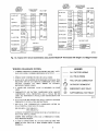
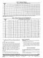
Fig. 4 shows
accessory
temperatures
tion Instructions
and code
snowfall
snow
stand
with
in areas
Refer
to provide
and ensure
unit with accessory
are encountered.
packaged
requirements
level
adequate
support
where
to separate
feet
prolonged
Installa-
accessories.
Roof mounted units exposed to winds above 5 mph may require
wind baffles to achieve adequate defrost. Consult Low-Ambient
Guideline for wind baffle construction.
NOTE: Unit must be level to within _+ 2 ° (_+ 3/8 in./ft) per
compressor manufacturer specifications.
Step 3_Clearance Requirements
When
installing,
allow
wiring,
refrigerant
piping,
sufficient
service
end of unit and 48 in. above
space
and service.
for
Allow
airflow
30-in.
clearance,
clearance
unit. For proper airflow,
to
a 6-in.
clearance
on 1 side of unit and 12 in. on all remaining
sides must
be maintained.
Maintain
a distance
of 24 in. between
units.
Position
directly
so water,
snow,
or ice from
root" or eaves
cannot
fall
on unit.
On rooI_Lop applications,
surface.
locate unit at least 6 in. above roof
A98534
Step 4_Operating
Ambients
Fig. 4---Accessory
The minimum outdoor operating ambient in cooling mode is 55°F,
and the maximum outdoor operating ambient in cooling mode is
125°F. The maximum outdoor operating ambient in heating mode
is 66°F.
_) Step 6_Check
Support Feet
Indoor and Outdoor AccuRater_
Piston
Check indoor coil piston to see if it matches the required piston
shown on outdoor unit rating plate. If it dees not match, replace
2