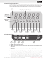
1
MSI9300
PortaWeigh Plus Crane Scales
PortaWeigh Plus Hi-Torque Crane Scales
Operator’s Manual
MSI-9300 Porta-Weigh+ Crane Scale
TABLE OF CONTENTS
SECTION 1 – INTRODUCTION & INSTALLATION .........................................................................................3
Introduction ...................................................................................................................................................3
Installation .....................................................................................................................................................3
Battery Removal & Replacement ..................................................................................................................4
Battery Life ....................................................................................................................................................5
Battery Charger..............................................................................................................................................5
FCC Statement...............................................................................................................................................6
MSI-9300 Porta-Weigh Plus Display ............................................................................................................7
Keyboard Operations .....................................................................................................................................7
SECTION 2 – SCALE OPERATION .............................................................................................................8
POWER .........................................................................................................................................................8
Multiple scale channels .................................................................................................................................8
ZERO .............................................................................................................................................................8
TARE .............................................................................................................................................................9
Special TARE Modes ..................................................................................................................................10
NET/GROSS ...............................................................................................................................................10
UNITS .........................................................................................................................................................10
TEST............................................................................................................................................................11
Internal Temperature Display ......................................................................................................................11
RF List .........................................................................................................................................................11
SECTION 3 – MSI-9300 SETUP MENU .................................................................................................12
Key Functions during Setup ........................................................................................................................12
Setup Menu Structure ..................................................................................................................................12
User Key Function .......................................................................................................................................13
Automatic Off ..............................................................................................................................................13
Units ............................................................................................................................................................14
Total .............................................................................................................................................................15
Automatic Temperature Display ..................................................................................................................16
RF LIST Scrolling .......................................................................................................................................16
SECTION 4 – RF REMOTE CONTROL .....................................................................................................18
Description ..................................................................................................................................................18
Functions .....................................................................................................................................................18
Setting the Transmitter Address...................................................................................................................18
Contention Considerations ..........................................................................................................................19
Battery Replacement ...................................................................................................................................19
RF Remote Control FCC Statement ............................................................................................................19
SECTION 4 – THE EMBEDDED CELLSCALE ............................................................................................20
Accessing The CellScale .............................................................................................................................20
Connection Procedure .................................................................................................................................20
Comm port Cable ........................................................................................................................................20
Set Points .....................................................................................................................................................21
Password Protection ....................................................................................................................................21
Scale Calibration .........................................................................................................................................21
Calibration Procedure ..................................................................................................................................22
CellScale Settings for MSI-9300 .................................................................................................................26
RF System Setup .........................................................................................................................................27
Legal Standard .............................................................................................................................................27
Setting the Legal Standard Mode ................................................................................................................27
Legal-For-Trade Control Device .................................................................................................................28
Sealing MSI-9300 Crane Scales ..................................................................................................................29
APPENDIX – SPECIFICATIONS & DIMENSIONS .........................................................................................31
Hardware Overview.....................................................................................................................................31
General Features ..........................................................................................................................................31
General Specifications .................................................................................................................................32
Dimensions and Load Train Specifications, Standard MSI-9300 ...............................................................33
Dimensions and Load Train Specifications, MSI-9300HT ......................................................................33
Options and Accessories ..............................................................................................................................34
The MSI Limited Warranty .........................................................................................................................34
Page 2 MSI-9300 Crane Scale™ • User Guide
MEASUREMENT
SYSTEMS
INTERNATIONAL
SECTION 1 – INTRODUCTION & INSTALLATION
INTRODUCTION
The Measurement Systems International MSI-9300 Series Porta-Weigh Plus Crane Scales are designed to
provide a rugged weight indicator and data system for any type and size of crane used in industry. Two basic
styles are available: MSI-9300 and MSI-9300HT. This guide is used for both versions as they have identical
electronics.
The standard MSI-9300 is supplied with rotating hooks or shackle interfaces. The MSI-9300HT Hi-Torque
version features a fixed load train that does not rotate and a new load cell design that withstands the induced
torque associated with power assisted rotating loads. With options available for both top and bottom interfaces, the MSI-9300HT easily integrates with existing powered rotators to provide safe material handling and
increased operational efficiency. The MSI-9300 Series combines CellScale technology with MSI’s advanced
Crane Scale architecture providing both a local and remote display capability. Combined with CellScale accessory components, they become advanced data gathering networks suitable for process control, safety monitoring, and weight related data collection.
The circuitry is fully shock-mounted and water proof making a robust
overhead weighing system for use indoors and out. The large 1.2” (30mm)
ultra bright LED readable at distances up to 50’ (15m). Display brightness can be set to automatically adjust to ambient lighting conditions for
optimum viewing and battery conservation.
DO
The MSI-9300 Series crane scales can communicate with CellScale family
indicators and modems at distances up to 1000’ (300m) outdoors (even
further with gain antennas). Both fixed and handheld indicators are available, as well as Modems for direct connection to computers. A remote
4-20mA interface is available for direct connection to PLCs and other
process control equipment. CellScale Virtual Monitor (CVM) software is
available to enable your PC to act as a full-featured digital scale indicator
with data logging capabilities.
INSTALLATION
The MSI-9300 installs easily by hanging it on the crane, using properly
sized shackles. Follow proper loading procedures to ensure that side loading is eliminated. Please refer to MSI’s brochure, “Crane Safety” when
installing model MSI-9300.
One of the most common installation problems is using an oversize
Rev 1 7/27/02 for SW Ver 1-1
USE HARDWARE THAT CREATES SINGLE
POINT ATTACHMENTS AND ALLOWS THE
SCALE FREEDOM OF ALIGNMENT.
DO NOT
DO NOT
DO NOT
1. DO NOT PUSH OR PULL ON LOADED
SCALE. 2. DO NOT PULL LATERALLY ON
HOOK WITH SCALE LOADED.
DO NOT INTERFACE HARDWARE
(SHACKLES, HOOKS ETC.) THAT ARE
OVERSIZED AND RESTRICT SINGLE POINT
LOADING AND SELF-ALIGNMENT WHICH
CAN RESULT IN OFF-AXIS LOADING.
DO NOT USE MULTIPLE ATTACHMENTS.
MSI-9300 Crane Scale™ • User Guide
Page 3
MSI-9300 Porta-Weigh+ Crane Scale
shackle or too large a hook to interface with the MSI-9300. This can cause off center loading and stress points
that will reduce the life of the MSI-9300 lifting eye or hook. Use the appropriate interface hardware for the
capacity of the scale. If your interface hardware does not fit properly, MSI can supply the MSI-9300 with
oversize lifting eyes or shackle interfaces. If the crane hook is too large to fit in the lifting eye with single point
interface, then install the scale using adaptive rigging.
If multiple attachments are needed, use a shackle or ring to attach the multiple lines to thus keeping a single
point attachment to the scale. Single point attachments are necessary to ensure the safety and accuracy of the
scale system.
Regular maintenance inspections of the lifting system should be performed to ensure safety. Pay particular
attention for signs of stress on any element in the load train.
BATTERY REMOVAL & REPLACEMENT
1) Turn the crane scale Off.
2) With one hand, hold the battery access to prevent it from falling.
3) Rotate the two cam-latch knobs counter-clockwise until the plate latches disengage.
4) Carefully back the plate out of the battery well.
5) Release the battery retaining strap.
Battery Access Plate
Cam-Latch Knobs
12V Sealed Lead Acid Battery
MSI P/N D00599-0004
The Battery Access Plate and
the Sealed Lead Acid Battery are
potential falling hazards. When
opening the battery access, be
sure to hold the battery to prevent
it from falling. This battery contains
Lead and should be recycled when
it has reached its end of life.
Page 4 MSI-9300 Crane Scale™ • User Guide
MEASUREMENT
SYSTEMS
INTERNATIONAL
6) Remove the battery by pulling straight back.
7) Install a fully charged battery by plugging it in to the exposed battery jacks. The crane scale will turn on
briefly then turn itself off.
8) Reattach the battery retaining strap.
9) Reseat the access panel.
10) Put pressure on the plate to partly compress the gasket. While applying pressure, turn the cam-latch knobs
clockwise until the plate is reseated. Make sure the plate is firmly in place.
BATTERY LIFE
The MSI-9300 battery life depends on a number of factors: Brightness of the LED and number of segments lit,
the amount of RF activity, and the age and condition of the SLA (sealed lead acid) battery. The MSI-9300 will
automatically turn the scale off when the SLA battery drops to approximately 10.5V. You must recharge the
battery when this happens. Leaving a discharged battery in the scale, which has a maintenance battery drain,
can result in a deep discharged battery which will shorten its service life.
SLA batteries do not suffer from memory effects and actually benefit from frequent rechargings. Recharge
the battery whenever it is convenient even when it still has available life. Due to the maintenance discharge
imposed on the battery by the MSI-9300 electronics, do not store the MSI-9300 more than 7 days with the
battery inside. Remove the battery.
Battery Use Guidelines
1) Recharge whenever convenient. Do not wait for the scale to shut itself off if your work situation permits.
2) If you need the scale continuously, keep a fully charged spare battery. Replace the drained battery as close
as possible to the low battery warning, or earlier.
3) SLA Batteries that have not been deep discharged should withstand 500 to 1500 charging cycles.
4) The low battery warning will indicate about 2-4 hours of additional use before the MSI-9300 turns itself
off.
5) If the MSI-9300 is not going to used again soon, remove the SLA battery to prevent deep discharge while
the unit is in storage.
BATTERY CHARGER
Each MSI-9300 Series crane scale is shipped with a battery charger (MSI P/N 502221-0001) designed to
charge and maintain the battery. Exact charging time will depend on the degree of discharge of the battery. A
battery removed when the low battery warning first appears should take about 4-6 hours to fully charge. A deep
discharged battery might take 24 hours to recover.
Using the Charger
1) Remove the Battery from the 9300. See previous page for removal instructions.
2) Connect the charger assembly to the AC supply (86-260VAC). The Power Status light should be green. If
the power status light fails to illuminate, check your AC power connection and make sure the VAC jack is
fully seated.
3) Plug in the polarized connector to the jacks on the battery.
4) The Charge Status light should turn ORANGE indicating fast charge.
If the status light remains Green when the battery is first plugged in, the battery may be defective.
5) Charge until the status light turns GREEN.
Deep discharged batteries may require a couple days to recover full charge.
When the charge cycle is complete you can (and should) leave the battery on the charger until it is needed. The
charger keeps a maintenance float charge on the battery to ensure the best possible operation times. For scales
that are in high usage, MSI recommends obtaining a spare battery so one can always be on the charger.
Rev 1 7/27/02 for SW Ver 1-1
MSI-9300 Crane Scale™ • User Guide
Page 5
MSI-9300 Porta-Weigh+ Crane Scale
Charge Indicator Light
Amber = Charging
Green = Float
The charger is a universal input type and is rated for 100-240VAC, 50-60Hz. AC power cords suitable for any
world location are available from MSI.
FCC STATEMENT
FCC ID: HSW-2450M
Note: This unit has been tested and found to comply with the limits for a Class A digital
device, pursuant to part 15 of the FCC Rules. These limits are designed to provide reasonable
protection against harmful interference when the equipment is operated in a commercial environment. This equipment generates, uses, and can radiate radio frequency energy and, if not
installed and used in accordance with the instruction manual, may cause harmful interference
to radio communications. Operation of this equipment in a residential area is likely to cause
harmful interference in which case the user will be required to correct the interference at their
expense.
Page 6 MSI-9300 Crane Scale™ • User Guide
MEASUREMENT
SYSTEMS
INTERNATIONAL
MSI-9300 PORTA-WEIGH PLUS DISPLAY
The MSI-9300 has six 1.2” (30.5mm) ultrabright LED Digits along with annunciators. The brightness of the
display is automatically adjusted to the lighting conditions. When the ambient light is dim, the LEDs are lower
in intensity. When ambient light is bright, the LED intensity level is increased to allow sunlight readability.
Light
Sensor
6 Digit Weight and Data Display
8. 8 . 8 . 8 . 8 . 8
Minus Sign
Only used when
six digits are displayed
Middle segment used
for ≤5 displayed digits
Center of Zero
Indicator
RF BAT
0
3
LOW
Tare
MOTION
Ttl Net Grs kg lb
2
1
Set Points
Displaying
Wt Unit is
Low Battery Displaying
1-3
Tare Wt
Net Wt
kilograms
Warning
RF Comm
Weight in
Displaying
Displaying
Wt Unit is
Indicator
Motion
Total Wt
Gross Wt
pounds
KEYBOARD OPERATIONS
POWER
ZERO NET/GROSS TARE
0
1
2
3
TEST
T
4
5
1) POWER – Push to turn the scale on or off.
2) ZERO – Used to zero the scale. The zero range is usually 100% of full scale unless prohibited by legal-for
trade settings.
3) NET/GROSS – Switches scale between NET and GROSS weight readings (assuming a Tare value has
been stored).
4) TARE – When in GROSS mode, pushing TARE will zero any weight on the scale and cause the scale to go
into the NET mode. When in NET mode, pushing TARE will display the TARE value for 2 seconds, then
revert back to the NET weight display. In NET mode, pushing TARE twice will set a new Tare. Pushing
TARE followed immediately by ZERO will clear the Tare value and revert the scale to Gross Mode
5) TEST/USER Key – When pushed, this causes a display segment check, and provides battery and RF
Network information. Also programmable for USER desired functions. See SETUP USER KEY. User Key
Functions Available: Units (kg/lb) • Total • Scan List Increment (multi-channel systems) • °F/°C • Change
Network (SW V3-33 and above) • Test (default)
Rev 1 7/27/02 for SW Ver 1-1
MSI-9300 Crane Scale™ • User Guide
Page 7
MSI-9300 Porta-Weigh+ Crane Scale
SECTION 2 – SCALE OPERATION
POWER
To Turn On the Power
1) Push POWER. The system performs a display
check: All segments and annuciators illuminate
for 3 seconds.
2) The LED displays the firmware Rev number.
3) Next, the display shows the Network address
followed by the ID address. This is the operating network address for any slave device to log
onto.
The network and ID Address are usually but not always the
same. Numbers for Network range from 0 to 31 and for address
from 0-254. Initially the MSI-9300 display will not know the Network address and will skip this step.
4) The display begins a numeric test while the
CellScale component is establishing Network
and Comm Port connections. The count up pattern will continue for 10-20 seconds and will
sometimes restart. This is normal.
5) Once the RF Network is established and the
Comm Port connection to the display is set the
display will indicate “ConEct” [sic]. The scale is
now ready for operation.
POWER
8.8.8.8.8.8
E00-25
nt
2
id
2
000000
11111
222222
Conect
1
2
3
3
4
4
4
5
MULTIPLE SCALE CHANNELS
MSI-9300 Series crane scales are capable of hosting multiple independent scale inputs. These are connected
via RF using MSI-6260CS and/or MSI-9300 Series crane scales setup as Network Slaves, or by special order,
additional inputs can be hard-wired directly. In addition, the CellScale Math channels can be used for manipulating the scale data. To directly access additional channels, the TEST/USER key can be programmed to “S
List” to scroll through the available scale channels. See “USER KEY FUNCTION” in this manual. See the
CellScale User Guide for the procedure to add additional channels. The crane scale’s keypad operates on the
displayed channel only.
ZERO
Sets the zero reading of the scale. Use the zero key to take out small deviations in zero when the scale is
unloaded. (See “TARE” for zeroing (Taring) package or pallet weights)
To Zero
Push ZERO. The weight reading must be stable within
±1 division for the zero function to work.
The backup memory stores the zero reading, and can restore it even if
power fails.
ZERO
0
0.0
The numeric digits display “0” (or 0.0 or 0.00, etc.).
Rules for Use:
1) Works in GROSS mode or NET mode. Zeroing while in Net mode will zero the gross weight causing the
display to show the negative Tare value.
2) The scale must be stable. The scale will not zero if the motion detect annunciator is on.
3) The scale will accept a zero setting over the full Range of the scale (NTEP and other Legal-for-trade
models may have a limited zero range). Zero settings above 4% of full scale will subtract from the overall
capacity of the scale. For example if you zero out 100 lb. on a 1000 lb. scale the overall capacity of the
scale will reduce to 900 lb. plus the allowed over-range amount.
Page 8 MSI-9300 Crane Scale™ • User Guide
MEASUREMENT
SYSTEMS
INTERNATIONAL
TARE
Tare is typically used to zero out a known weight such as a packing container or pallet and display the load in
NET weight. A Tare value is entered in one of three ways:
1) AUTO TARE – When the TARE key is pushed twice, the current weight is zeroed and Net Weight is displayed. This is the only Tare function available from the MSI-9300 keypad.
2) KEYBOARD TARE – Available from a 3750CS or 9750A Indicator only. Using the numeric keys, the
operator keys in the desired Tare Weight then pushes the ENTER Key. See the 3750CS or 9750A User
Guides.
3) TARE UP/DOWN – Available from a 3750CS Indicator only. Using the Scroll Keys, the Tare value is
changed one scale division at a time. TARE UP/DOWN is useful for increasing or decreasing the current Tare value slightly. The Keyboard Tare and Tare Up/Down modes can be disabled through the use
of SETUP TARE. In the “AUTO” mode a single push of the TARE key will enact AUTO TARE. See the
3750CS User Guide.
To Auto Tare (in Gross Mode)
1) From Gross Mode, push TARE. The current weight is
stored in the Tare register, the display mode changes
to Net, and the display reads 0. All following readings are deviations from the set Tare value.
TARE
1
T
Net
0
To Read the Current Tare Value
1) From Net Mode, push TARE. The current weight
stored in the Tare register is displayed for 2 seconds.
Then the display mode reverts to Net Weight.
TARE
1
T
2
1234
Tare
4444
Net
To Auto Tare (in Net Mode)
1) From Net Mode, push TARE. The current Tare value
is displayed.
2) Within 2 seconds, push TARE again. Assuming no
motion, the current Gross weight is stored to the Tare
register, and the mode is set to Net weight with the
new tare value. All following readings are deviations
from the set Tare value.
TARE
1
T
TARE
2
T
1234
Tare
0
Net
To Clear Tare and Revert to Gross Mode
Use the Net/Gross to return to Gross Mode without clearing the Tare value.
1) From Net Mode, push TARE. The current Tare value
is displayed.
2) Within 2 seconds, push ZERO. The current Tare
weight is cleared from the Tare register, and the mode
is set to Gross weight.
TARE
1
TARE
2
Rev 1 7/27/02 for SW Ver 1-1
T
T
1234
Tare
5565
Gross
MSI-9300 Crane Scale™ • User Guide
Page 9
MSI-9300 Porta-Weigh+ Crane Scale
Tare - Rules for Use:
1) Only positive gross weight readings can be tared. Weight can be tared in both the NET and GROSS
modes. When in the NET mode, the TARE is not cumulative, all the weight is zeroed.
2) The motion annunciator must be off. The weight reading must be stable.
3) Setting or changing the tare has no effect on the Gross zero setting.
4) Taring will reduce the apparent over range of the scale. For example, taring a 10 lb. container on a 60
lb. scale, the scale will overload at a net weight of 50 lb. (60-10) plus any additional allowed overload
(usually ~4% or 9d).
5) The scale stores the Tare value in the current ID Code memory until cleared. Each available ID Code
can store independent Tare values.
Multiple Tare Memories
MSI-9300 Series crane scales are capable of storing Tare values through the use of the ID Codes. Each ID code
stores an independent Tare. ID Codes are accessible through the MSI-3750CS, MSI-9750A or MSI-9850, or
through a MSI-9020 CellModem using Host Commands.
SPECIAL TARE MODES
The Tare function has two special modes. These modes are configured through the Comm Port. See the MSI9000 CellScale User Manual for information on configuring the Tare Mode.
UNIV TAR
The Universal Tare feature allows a single Tare value to be shared by all ID Codes. With UNIV TAR enabled
the individual Tares stored with each ID Code are ignored (but not erased). Disabling UNIV TAR will restore
the original Tare values. UNIV TAR is intended for those applications where a common carrier or pallet is
used, but multiple ID Codes are necessary for data collection.
AUTO CLR
Enabling “AUTO CLR” causes the MSI-9300 to clear the Tare Value after each lift greater than 0 NET. The
Tare Value is cleared and the display mode reverts to Gross Weight once the load is removed (the weight goes
below 0 NET). The “ON TOTAL” setting clears the Tare Value after the load is totaled. The default for the
“AUTO CLR” function is “DISABLED” . When disabled, the Tare Value can only be cleared manually (see
“To Clear Tare and return to Gross Mode”.)
NET/GROSS
Switches the display between Net and Gross modes. Net Weight is defined as Gross Weight minus a Tare
Weight.
To Switch Between Net Mode and Gross Mode
Switching back to Gross mode from Net mode will not clear the Tare value. This allows the operator to use the Gross Mode temporarily without having to reestablish the Tare value. Only manually clearing the Tare or setting a new Tare will change the tare value held before switching into Gross Mode.
OIML Legal-for-trade units only: The NET/GROSS key is temporary action only. The Gross weight is displayed for 2 seconds and then the display
returns to the Net Mode. The only way to return to permanent Gross readings is to clear the Tare (see Clear Tare procedure).
1) Starting in the NET weight mode, push NET/GROSS.
The weight mode will change to Gross weight.
If you are in Gross Mode and a Tare value has not been established, the
Net/Gross key has no effect.
2) Pushing NET/GROSS again will revert the display to the
NET mode.
NET/GROSS
1
NET/GROSS
GRS
NET
2
UNITS
Allows easy weight units conversions. Although the CellScale offers up to 8 units, the MSI-9300 will only
display pounds or kilograms.
This operation requires that the Test/User Key function is set to Units. See “Setup USER key Function ”.
To Change the UNITS
Push the TEST/USER key (programmed as UNITS). The
weight display will toggle between kg and lb.
Page 10 MSI-9300 Crane Scale™ • User Guide
TEST
1
TEST
kg
lb
MEASUREMENT
SYSTEMS
INTERNATIONAL
TEST
Provides a functional system test, and an on-demand display check without disturbing the current weighment.
The Test function can be interrupted by pushing any key during the test.
To start the Test
Push the TEST/USER key (programmed as TEST). The
display will do the following steps:
1) All LEDs are illuminated for 1 second.
2) The battery condition in approximate per cent of remaining life is displayed.
3) The Network Address is displayed.
Numbered from 0-31
4) The Network ID is displayed.
TEST
1
2
3
4
Numbered from 0 to 254
5) The display digits count up from 0 to 9.
5
6) Returns to normal weight mode.
8.8.8.8.8.8
b= 80.5
nt 17
id 17
000000
111111
999999
INTERNAL TEMPERATURE DISPLAY
The MSI-9300 can monitor its internal temperature. This feature is for use in Foundry applications or any other
Crane use around high temperature sources. The temperature display can be set to display automatically at 20
second intervals (see page 15) and will display in degrees C or degrees F. The purpose of monitoring the internal temperature is to ensure that the scale is not damaged by overlong exposure to high temperatures. The MSI9300 offers a heat shield option for foundry use that increases the dwell time possible when lifting melt pots.
MSI-9300 Series Crane Scales must be immediately removed from the high heat source when the internal temperature reaches 158°F or 70°C.
To Manually Display the MSI-9300 Internal Temperature
USER key Function set to “ °F °C ”. Temperature units are set in the Setup Menus.
Push the TEST/USER key. The current internal temperature will display for 2 seconds.
TEST
71. 2 °C
RF LIST
When the scale is used in multiple RF Networks, the RF List function allows the user to easily switch between
several networks. These networks must be setup in the embedded CellScale (See MSI-9000 User Guide).t
This operation requires that the Test/User Key function is set to RFList. See “Setup USER key Function ”.
Rev 1 7/27/02 for SW Ver 1-1
MSI-9300 Crane Scale™ • User Guide
Page 11
MSI-9300 Porta-Weigh+ Crane Scale
SECTION 3 – MSI-9300 SETUP MENU
KEY FUNCTIONS DURING SETUP
POWER
ZERO NET/GROSS TARE
0
3
TEST
T
2
1
1) The Test key is used to scroll through menu selections.
2) The Tare key is used to select the displayed menu choice.
3) The Zero key is used to exit out of the current menu. At the root level the Zero key turns off the Setup
mode and returns the MSI-9300 to weight display.
To Start the Setup Menu
1) If the MSI-9300 is on, turn it off with the POWER key.
2) Press and hold the TEST key.
3) While still holding the TEST key, turn on the MSI-9300
with the POWER key.
4) Release the TEST key after the segment test screen is finished.
5) After a few seconds, the display will show the first Setup
Menu item, “FUNC”.
TEST
hold
POWER
TEST
8.8.8.8.8.8
release
Func
SETUP MENU STRUCTURE
TEST
POWER
MAIN
SETUP MENU
TEST
UNIT
S LIST
°F °C
rFList
OFF
TOTAL
Func
TEST
Hold Down
Let Go of Test
w/ Power Off >1 s after Display
turns on.
A-OFF
TEST
Unit
TEST
kg
lb
totAL
TEST
° Auto
TEST
° Unit
TEST
Page 12 MSI-9300 Crane Scale™ • User Guide
OFF
ENABLE
°F
°C
USER KEY
FUNCTION
MENU
AUTO OFF
MENU
OFF
0.16 hr
0.5 hr
1 hour
OFF
AUTOLD
AUTONR
AUTOPE
PRESS
TOTAL MODE
MENU
MEASUREMENT
SYSTEMS
INTERNATIONAL
USER KEY FUNCTION
The TEST/USER key can be programmed to 1 of 6 functions:
1) TEST – Default function. Provides segment test of the display, battery level, and RF Network information.
2) UNIT – Switch between pounds (lb) and kilograms (kg).
3) S LIST – (Scan List) Change displayed channel to the next channel in the CellScale Scan List. Applicable
to multichannel systems only.
4) °F °C – Displays the internal MSI-9300 temperature for 2 seconds.
5) OFF – No function
6) TOTAL – If manual total is enabled, pushing the TEST/USER key will add the current weight to the
Total register. Subsequent pushes will display the totaled weight until Total is reset by returning to zero
(below the total threshold, see the CellScale User Guide for more information on total threshold). If in any
Auto-Total mode, the USER key functions as View Total, displaying the Total Weight for two seconds.
To Set the User Key Function
1) Start the Setup Mode using the procedure on the previous
page.
2) With the display reading “Func” press the TARE (Select)
key. The currently programmed USER key mode will display flashing.
The example assumes the dejault function TEST is the current USER key
function.
1
TARE
2
T
TEST
3
TEST
3
TEST
3) Use the TEST (Scroll) key to scroll through the choices.
In this example the TEST key function will be changed to TOTAL.
4) When the desired choice is shown, Press TARE (Select)
to select it.
Pushing TARE (Select) places the displayed function as the USER key function, and exits the FUNC menu.
3
TEST
3
TEST
3
TEST
3
5) The next Main Menu item, “A-OFF” will appear. Either
select another Setup procedure with the TEST (Select) key,
or return to weighing mode by pushing ZERO (Exit).
TARE
4
T
Func
test
Unit
S List
°F °C
rFLiSt
OFF
totaL
A-OFF
ZERO
5
0
TEST
to exit
to select other Main
Setup Menu items.
5
AUTOMATIC OFF
The MSI-9300 can be set to turn itself off in periods of inactivity by enabling the Automatic Off feature. The
Auto Off timer is reset whenever a button is pushed or weight changes. There are 4 settings:
1) OFF – Feature disabled
2) 0.16 hr – MSI-9300 will turn off in approximately 10 minutes
3) 0.5 hr – MSI-9300 will turn off in ~30 minutes
4) 1 hour – MSI-9300 will turn off in ~1 hour.
Rev 1 7/27/02 for SW Ver 1-1
MSI-9300 Crane Scale™ • User Guide
Page 13
MSI-9300 Porta-Weigh+ Crane Scale
To Setup Automatic Off
1) Start the Setup Mode using the procedure on page 12.
2) Use the TEST (Scroll) key to scroll to “A-OFF”.
1
TEST
2
TARE
3) With the display reading “A-OFF” press the TARE
(Select) key. The currently programmed Auto-Off setting
will display flashing.
The example assumes the Auto-Off function was OFF.
4) Use the TEST (Scroll) key to scroll through the choices.
3
T
TEST
4
TEST
4
TEST
In this example the Auto-Off function will be set to 1 hour.
5) When the desired choice is shown, Press TARE (Select)
to select it.
Pushing TARE (Select) places the displayed setting as the Auto-Off mode,
and exits back to the Main Setup Menu.
4
TARE
5
T
Func
a-Off
OFF
0.16 hr
0.50 hr
1 hour
Unit
ZERO
6) The next Main Menu item, “Unit” will appear. Either 6
to exit
select another Setup procedure with the TEST (Select) TEST
key, or return to weighing mode by pushing ZERO 6
to select other Main
(Exit).
Setup Menu items.
0
UNITS
The MSI-9300 will display and convert weight in pounds or kilograms. The TEST/USER key can be set to
switch between lb and kg if desired. If only 1 weight unit is needed, use this procedure to set the desired unit.
To Setup the Weight Unit
1) Start the Setup Mode using the procedure on page 12.
2) Use the TEST (Scroll) key to scroll to “Unit”.
1
TEST
2
TEST
3) With the display reading “Unit” press the TARE (Select)
key. The currently programmed Unit setting will display
flashing.
2
TARE
3
4) Use the TEST (Scroll) key to switch between kg and lb.
In this example the unit will be changed to kg.
5) When the desired choice is shown, Press TARE (Select)
to select it.
Pushing TARE (Select) sets the weight unit, and exits back to the Main Setup
Menu.
6) The next Main Menu item, “Total” will appear. Either
select another Setup procedure with the TEST (Select) key,
or return to weighing mode by pushing ZERO (Exit).
TEST
4
TARE
5
T
lb
Unit
kg
totaL
ZERO
6
0
TEST
to exit
to select other Main
Setup Menu items.
6
Page 14 MSI-9300 Crane Scale™ • User Guide
T
Func
a-Off
Unit
Unit
MEASUREMENT
SYSTEMS
INTERNATIONAL
TOTAL
The MSI-9300 CellScale feature set provides Total and Statistics capabilities. The MSI-9300 keypad allows the
enabling and display of some of these features. More extensive total and statistics capability is provided when
a 9750A or 3750CS meter is part of the network. However, the MSI-9300 allows the setting of the following
Total features:
1) OFF – Total feature turned off
2) Autoload – The autoload feature provides an algorithm for totaling that requires a 3750CS equipped with
an auxiliary push button. Intended for commodity loading into containers. See the CellScale User Guide
for a complete description of the Autoload feature.
3) Autonorm – The Autonorm Total will automatically total all steady weights above the auto total threshold.
Once totaled, the weight must return to near zero before the scale will autototal again. The autonorm
total totals the last settled weight before the scale went back to zero, so be sure the weight is removed
rapidly from the scale.
4) Autopeak – Similar to Autonorm except the weight totaled will be the highest settled weight before the
weight returns to near zero.
5) Press – Indicates that a manual total key must be pressed to cause a total to occur. This can be the USER
key programmed to total, or total keys found on the 3750CS or 9750A indicators.
To Set the Total Mode
1) Start the Setup Mode using the procedure on page 12.
1
TEST
2) Use the TEST (Scroll) key to scroll to “Total”.
2
TEST
3) With the display reading “Total” press the TARE (Select)
key. The currently programmed Total setting will display
flashing.
2
TEST
2
TARE
4) Use the TEST (Scroll) key to scroll through the total
modes.
In this example the mode will be changed to “AutoNorm” (AutoNr).
3
T
TEST
4
TEST
5) When the desired choice is shown, Press TARE (Select)
to select it.
Pushing TARE (Select) sets the Total mode, and exits back to the Main
Setup Menu.
4
TARE
5
T
Func
a-Off
Unit
totaL
OFF
autoLd
autoNr
° Auto
ZERO
6
to exit
6) The next Main Menu item, “° Auto” will appear. Either TEST
select another Setup procedure with the TEST (Select)
6
to select other Main
key, or return to weighing mode by pushing ZERO Setup Menu items.
(Exit).
0
Rev 1 7/27/02 for SW Ver 1-1
MSI-9300 Crane Scale™ • User Guide
Page 15
MSI-9300 Porta-Weigh+ Crane Scale
AUTOMATIC TEMPERATURE DISPLAY
The MSI-9300 will display its internal temperature once every 20 seconds if enabled with the following procedure.
To Enable Auto Temp Display (° Auto) & Set Temperature Units
1) Start the Setup Mode using the procedure on page 12.
2) Use the TEST (Scroll) key to scroll to “° Auto”.
3) With the display reading “° Auto” press the TARE (Select)
key. The currently programmed Auto-Temperature setting will display flashing.
4) Use the TEST (Scroll) key to Enable the Auto-Temperature mode.
5) When the desired choice is shown, Press TARE (Select)
to select it.
Pushing TARE (Select) sets the Auto-Temp mode either OFF or Enable, and
exits back to the Main Setup Menu.
6) The next Main Menu item, “° Unit” will appear. Push
TARE (Select) to setup the desired temperature unit (°F
or °C).
7) Use the TEST (Scroll) key to select °C or °F.
8) Push TARE (Select) to set the temperature unit.
9) The next Main Menu item, “Func” will appear. Either
select another Setup procedure with the TEST (Select)
key, or return to weighing mode by pushing ZERO
(Exit).
1
TEST
2
TEST
2
TEST
2
TEST
2
TARE
3
T
TEST
4
TARE
5
T
TARE
6
T
TEST
7
TARE
8
T
Func
a-Off
Unit
totaL
° Auto
OFF
EnAbLe
° Unit
°F
°C
Func
ZERO
9
0
TEST
to exit
to select other Main
Setup Menu items.
9
RF LIST SCROLLING
The internal RF modem can be preconfigured with up to 8 RF Network assignments. This allows the scale to
move from network to network without having to hook up a computer to change the network assignments. The
RF List must be originally configured in the embedded CellScale using the Terminal Access Mode. Once the
RF List is programmed, the user can change networks with the following procedure.
1) Program the USER key to “rFLiSt” using the procedure
on page 12.
2) Press the TEST/USER key to display the current network
setting. The first two digits are the Network, the second 3
digits are the new “My ID”.
3) Press the TEST key to scroll through the Network choices.
Up to 8 networks can be configured.
To exit without changing the Network Settings, press the ZERO key at any time.
4) When the desired Network setting is shown, press TARE
Page 16 MSI-9300 Crane Scale™ • User Guide
1
TEST
2
TEST
3
TEST
3
TEST
3
Func
1- 21
2- 21
12- 56
14-232
MEASUREMENT
SYSTEMS
INTERNATIONAL
(Select) to select it.
TARE
Pushing TARE (Select) reconfigures the Modem to new network settings.
5) The display will go into test mode while the network settings are being altered. When the modem is successfully
changed, the display will return to the weight mode.
4
T
5
5
000000
111111
222222
ZERO
0
to cancel and exit
To Change Current RF Network
This feature is intended for use in large installations where, for service or work load purposes, the crane scale
must be used on a new network. When the crane scale is a remote (slave) device, the Master CellScale must be
configured with a matching channel 5 scanlist to allow seamless Network migration. In other words, the “MY
ID” must be identical to the unit it is replacing. Make sure two remote devices with the same “My ID” are
never on at the same time in the same Network.
When the crane scale is a Host (Master) device, only the network number can be changed, the master “My ID”
will not change. All remote devices on the previous network will lose communciation.
Rev 1 7/27/02 for SW Ver 1-1
MSI-9300 Crane Scale™ • User Guide
Page 17
MSI-9300 Porta-Weigh+ Crane Scale
SECTION 4 – RF REMOTE CONTROL
DESCRIPTION
MSI-9300 Series crane scales can be equipped with an RF Remote Control (RFRC). This differs from using
the MSI-9750A or MSI-3750CS Indicators to control the scale. The RFRC is a transmit only device that can be
used to perform basic scale functions. It does not have the range of the Spread Spectrum modems built into the
RF versions of MSI-9300 Series crane scales and is intended for local control only. Range will vary from 25’ to
100’ depending on room conditions and line of sight to the display. The remote receiving antenna is behind the
red lens of the crane scale and best range will occur when the display is visible to the operator using the RFRC.
One big advantage the RFRC provides is the ability to turn the unit on remotely. The RFRC can also be used in
systems that do not have the RF Modem.
The RFRC is available in three versions differing only in transmit frequency. The standard version operates at
418MHz. Available alternative frequencies are 315MHz and 433MHz.
FUNCTIONS
The RF Remote control duplicates the functions of the front panel keys on
MSI-9300 Series crane scales. The POWER, ZERO, NET/GROSS, and TARE
key function identically. In addition, the RFRC adds direct control of TOTAL
and VIEW TOTAL without the use of the USER key. The TOTAL still needs to
be enabled and configured in the embedded CellScale before these features will
function properly. See page 14 for the procedure to set up the Total mode.
The F2 key is programmed to trigger a remote print. When F2 is pressed, the
crane scale will transmit the data string programmed in the virtual Comm Port
3 of the embedded CellScale. This data string can be used in a variety of ways.
For example, a remote printer can be connected to the MSI-9020 CellModem.
When F2 is pressed, the remote printer could print the weight along with time,
date, total weight, or any other data parameter available from the embedded
CellScale. Another common use is to send the weight data to a computer configured to data log the information to a database.
For information on Data Strings and the use of Virtual CommPort 3, refer to the
MSI-9000 CellScale Users Guide. F3 and F4 are not supported by MSI-9300
Series crane scales. These keys function as TOTAL and VIEW TOTAL (∑).
SETTING THE TRANSMITTER ADDRESS
In order to allow the formation of up to 1024 unique
Transmitter-Receiver relationships, the transmitter’s
address may be selected using internal DIP switches as
shown. The switches are accessed by removing the DIPswitch access cover.
If the switch is on, the address line is connected to ground, otherwise it is floating. The receiver’s address must match in order for the units to communicate.
MSI supplies the transmitter and receiver as a matched
set with the DIP switches already configured. A replacement RFRC will only need to have the transmitter DIP
switch set. To change the DIP switch in the receiver
requires disassembly of the crane scale front casting.
Due to differing DIP switch styles, the receiver DIP switch appears opposite to that
of the transmitter. On the receiver, the OFF position is on the right, and the ON
position is on the left.
Page 18 MSI-9300 Crane Scale™ • User Guide
Scale Remote Controller
ZERO
F1
F2
TARE
NET
GROSS
TOTAL
VIEW ∑
F3
F4
Measurement Systems International
The F1 key functions the same as the TEST/USER key on the front panel. The
exact function of this key depends on the USER key setup procedure. See page
12 for the procedure to configure the USER key which will also configure the
F1 key on the remote. Since the RFRC has a dedicated key for Total, there is no
need to program the USER key to Total, and it can be used for other purposes.
MEASUREMENT
SYSTEMS
INTERNATIONAL
CONTENTION CONSIDERATIONS
It is important to understand that only one transmitter at a time can be activated within a reception area. While
the transmitted signal consists of encoded digital data, only one carrier of any frequency can occupy airspace
without contention at any given time.
BATTERY REPLACEMENT
The remote unit utilizes a CR-2032 Button Lithium Cell. In normal use it will provide
1-2 years of operation. Access for replacement is accomplished by removing the battery
access cover by pressing down firmly on the label area and sliding it off. Once the unit is
open, remove the battery by sliding it from beneath the holder. Replace the cell with the
same type while observing the polarity shown.
RF REMOTE CONTROL FCC STATEMENT
INSTRUCTION TO THE USER
This equipment has been tested and found to comply with the limits for a Class B digital device, pursuant to
Part 15 of the FCC Rules. These limits are designed to provide reasonable protection against harmful interference in a residential installation. This equipment generates, uses and can radiate radio frequency energy and,
if not installed and used in accordance with the instructions, may cause harmful interference to radio communications. However, there is no guarantee that interference will not occur in a particular installation. If
this equipment does cause harmful interference to radio or television reception, which can be determined by
turning the equipment off and on, the user is encouraged to try to correct the interference by one or more of the
following measures: Reorient or relocate the receiving antenna. Increase the separation between the equipment
and receiver. Connect the equipment into an outlet on a circuit different from that to which the receiver is connected. Consult the dealer or an experienced radio/TV technician for help.
This equipment has been certified to comply with the limits for a Class B computing device, pursuant to FCC
Rules. In order to maintain compliance with FCC regulations, shielded cables must be used with this equipment. Operation with non-approved equipment or unshielded cables is likely to result in interference to radio
and TV reception. The user is cautioned that changes and modifications made to the equipment without the
approval of manufacturer could void the user’s authority to operate this equipment
Rev 1 7/27/02 for SW Ver 1-1
MSI-9300 Crane Scale™ • User Guide
Page 19
MSI-9300 Porta-Weigh+ Crane Scale
SECTION 4 – THE EMBEDDED CELLSCALE
For a complete guide to all the features of the embedded CellScale, refer to the MSI-9000 User Guide.
ACCESSING THE CELLSCALE
MSI-9300 Series crane scales are a shell interface to an embedded CellScale. To access the advanced features
of the CellScale, a Comm Port is provided on the front casting of the crane scale. This Comm Port is only used
for interfacing to the embedded CellScale and cannot be used as an output of any kind.
The CellScale offers Set Points, ID Codes, and other advanced features which are controlled either through a
remote Indicators such as the MSI-3750CS, the MSI-9850, or the MSI-9750A Handheld. These features are
also accessed by connecting a terminal program in a PC to the Comm Port. Tested terminal programs that
function well with the CellScale include ProComm Plus, Qmodem, HyperTerm (shipped with many versions
of Windows), WinTerm, and ZTerm (for Macintosh). Usually a VT102 emulation is used. All commands are
single key except when entering data.
Settings for your terminal program are: 9600 baud, 8 bit, 1 start bit, 1 stop bit, no parity, Handshaking usually
not required, but you can turn on Xon/Xoff if you desire.
While the Comm Port is in use, the display of the MSI-9300 Series crane scale is in standby with the message
“C-Port” or “H-Port” displayed. The only key that will function in this mode is the Power key.
The CellScale Terminal Access Mode is used to set Network parameters, Scale parameters, Set Points, and
other various setup conditions. Refer to the MSI-9000 CellScale User Guide for detailed information. The Terminal Access Mode is used for calibration on MSI-9300 Series crane scales that do not have the RF modem.
CONNECTION PROCEDURE
The MSI-9300 must be on and finished with its startup sequence before connecting the
terminal cable to a PC.
1) Without connecting the PC or Terminal to the MSI-9300, turn the MSI-9300 on. Wait for the startup
sequence to complete (usually about 10-15 seconds). When weight is displayed, the MSI-9300 is ready.
2) Press and Hold the NET/GROSS key and then push TEST. The display should change to “H-PORT”.
3) Connect the PC to the MSI-9300 through the Comm Port. Start your terminal emulation program with settings 9600-N-8-1
4) You can now access the Terminal menus in the CellScale. Push any key to refresh the menu.
5) Once in the Terminal Access Mode menus, commands are usually a single number or letter. Refer to the
9000 CellScale User Guide for further information.
COMM PORT CABLE
The MSI-9300 comes standard with one Comm port cable wired for RS-232 (MSI P/N 501705-0001) following the AT standard for 9 pin serial cables (DCE). An unterminated cable is available (MSI P/N 12023) if you
wish to wire your own serial cable for RS-232.
Comm Port Cable Color Code RS-232
Brown – Transmit output from CellScale, connect to
receive of DTE.
Black – Receive input to CellScale, connect to transmit of DTE.
Grey – CTS Input to CellScale. Connect to RTS or
RTR output of DTE.
White – RTS/RTR output from CellScale. Connect to
CTS input of DTE.
Blue – Signal Ground
Drain Wire – Connect to metal shell.
Page 20 MSI-9300 Crane Scale™ • User Guide
RS-232 DCE
Standard wiring for direct
9000 to Computer connection
Jumper 1-6-4
6
Grey (CTS)
White (RTS)
7
8
(NC) 9
1
2
3
Brown (TD)
Black (RD)
4
5
9-Pin Female ‘D’
Solder Cup View
Blue (GND)
MEASUREMENT
SYSTEMS
INTERNATIONAL
SET POINTS
The Internal CellScale can monitor up to 32 Set Points. Set Points are used for safety warnings and process
control. The MSI-9300 has LED annunciators for Set Points 1 through 3. Set Points are programmed from a
3750CS, a 9750A, or through the Terminal Access Mode. On special order MSI can supply audible alarms,
sirens, or other warning devices for Set Point outputs.
PASSWORD PROTECTION
The calibration and setup features in the MSI-9300 Series crane scales can be protected from tampering
through the use of passwords. Passwords can be up to 20 characters long. Be sure to record your password(s).
The default password is just a return. You can lock features without passwords to prevent accidental feature
changes. Password protection of calibration is not required for LFT scales as they are protected with a seal
switch.
Main CellScale Menu ➔ (4) Feature Locks / Passwords
***** Feature Locks/Passwords Setup *****
(1)
(2)
(3)
(4)
(5)
(6)
(7)
(8)
(9)
(ESC)
Calibration
Channel menu
Communications
NTEP
Product ID menu
Radio menu
Set Points menu
Strings menu
Individual Features
Exit
Main CellScale Menu ➔ (4) Feature Locks / Passwords ➔ (1) Calibration
***** Calibration Lock *****
(1)
Calibration password is:
(2)
Calibration is:
(ESC)
Exit
None
Un-Locked
This menu is typical of all the lock menus. You can assign a separate password to any major feature. To lock
a feature or menu, press 2 change from “Un-locked” to “Locked”. When a feature is locked, entering into the
menu will require the password before proceeding. To lock all channel related setups, MSI recommends locking the Channel menu (choice 2). This prevents tampering of calibration and all parameters related to scale
performance.
SCALE CALIBRATION
MSI-9300 Series crane scales are best calibrated using a remote indicator such as the MSI-3750CS, MSI-9850,
or the MSI-9750A Handheld. Calibration procedures using these devices are covered in their respective User
Guides. If the crane scale is not RF equipped, the only way to calibrate it is through the Comm Port using the
Terminal Access Mode.
MSI recommends having test weights of at least 50% capacity to properly calibrate the Crane Scale. The calibration procedures will operate with as little as 12.5% of capacity, though rated accuracy cannot be guaranteed.
Very large capacity scales are often calibrated using transfer techniques. Weigh something on a truck scale,
then pick it up on the Crane scale and match the weight during the calibration procedure. The CellScale software permits multi-point calibration (up to 9 span points + Zero). MSI Crane Scales are very linear from zero
to capacity, and therefore, usually do not require Multi-Point calibration. The need for Multi-Point calibration
is left up to the Scale Technician.
Legal-for-Trade Units
To calibrate LFT units, you must first press the pushbutton found behind the seal screw on the front panel (see
figure 4-1). Sealing instructions are found on page 29.
Calibration Tips
1) Make sure that the scale and load are stable (not swinging or vibrating) for every calibration step.
2) Prevent off-center loading during calibration. The scale must be perpendicular to the earth to prevent
Rev 1 7/27/02 for SW Ver 1-1
MSI-9300 Crane Scale™ • User Guide
Page 21
MSI-9300 Porta-Weigh+ Crane Scale
cosine theta errors. Adjust the rigging as necessary so that the pull is straight through the center of the
scale.
3) Calibration always starts with the zero load. Remove all rigging that is not always present on the scale.
However, it is sometimes best to calibrate zero with the rigging necessary for picking up the test weights
attached to the scale. It’s effect on dead load can be zeroed out later.
4) If rigging has not been zeroed out, make sure you add its weight to the test weight when entering the calibration weight.
5) Multi-point calibration can be done in any random order, as long as the zero step is first.
CALIBRATION PROCEDURE
The following procedure assumes the scale can be unloaded to perform a zero reading.
1) Connect a terminal (or computer with a terminal program) to the crane scale’s Comm port. Settings for
your terminal program are: 9600 baud, 8 bit, 1 start bit, 1 stop bit, no parity, Handshaking is usually not
required, but you can turn on Xon/Xoff if you desire.
2) The crane scale display should read “C-Port”. If not proceed anyway. Step 3 will reconfigure the Comm
Port.
3) Press and Hold NET/GROSS then press USER. The LED should read “H-Port”. Press [RETURN] on your
terminal program. The CellScale main menu should appear.
---------- MSI 9000 - CellScale ---------- (c) 2005 Measurement Systems International ---------------------------------------------13:48:06
(1)
(2)
(3)
(4)
(5)
(6)
(7)
(8)
10/02/05
Channels/Calibration
Communications
Display
Feature Locks/Passwords
Product IDs
Set Points
System
About...
Enter choice :
4) Select “Channels / Calibration” by pressing the terminal’s [1] key. The Channel Setup menu appears or a
dialog box asks you to press the sealed calibration keys (Standard set for NTEP or OIML mode).
***** Channel Setup *****
(1)
(2)
(3)
(4)
(5)
(6)
(7)
(8)
(9)
(a)
(b)
(c)
(ESC)
Channel Calibration
Data backup
Filter (software)
Channel Scanlist functions
Motion Compensation (Accelerometer option required)
Motion Detection
Tare
Total
Units Lock
Zero
Standard Mode: Industry
4 to 20mA
Exit
5) Start the Calibration procedure by pressing [1]. The “Choose Channel to Calibrate” menu appears. This
menu allows you to select which channel is to be calibrated. It uses the Scan List to identify which channels are available for calibration.
For multiple channel systems, the channel list must be set up before starting the calibration procedure. See Section 4 in the MSI-9000 CellScale User Guide.
Page 22 MSI-9300 Crane Scale™ • User Guide
MEASUREMENT
SYSTEMS
INTERNATIONAL
***** Choose Channel Parameters *****
(1)
(2)
(3)
(ESC)
Continue. These settings are correct
Choose the channel to calibrate:
Calibration timeout:
Exit
1-1
10 minutes
6) If the desired channel is already displayed, press [1] to continue to the next step. The channel number is
changed by pressing [2] until the desired channel to calibrate is displayed. This is typically 1-1 on MSI9300 Series crane scales. Dual load cell systems might have a channel 2-1 for the second load cell. Once
the correct channel is shown, press [1] “Continue ...”.
NOTE: Channel default is the first active channel. In this case, 1-1. It is also recommended to change the calibration timeout to NONE, by pressing [ 3 ], until
menu item 3 indicates: NONE.
7) The Channel Calibration menu appears. If the CellScale channel has never been calibrated, then you must
select [1]. If this is a recalibration for the same capacity, count-by (d) and calibration units, then you can
skip to step 10 by pressing [2]. Press [2] only if the settings at the bottom of the screen match the capacity
and resolution requirements.
***** Channel Calibration *****
(1)
(2)
(3)
(4)
(ESC)
Perform a completely new calibration
Re-do the current calibration
Manually adjust current cal points
Reset all cal parameters to defaults
Exit
Calibrate channel #:
The channel name is:
Calibration Capacity:
Calibration Countby:
Calibration Units:
1-1
Fred2...............
1000.0
0.2
Pounds
8) The CellScale prompts for the calibration unit. Chose the desired unit. In this example we will choose kilograms (2). MSI-9300 Series crane scales only have annunciators for pounds and kilograms.
Your choice of calibration unit does not prevent you from displaying the weight in any other unit. Select the unit matching your test weights.
***** Choose Calibration Units *****
(1)
(2)
(3)
(4)
(5)
(6)
(7)
Pounds
Kilograms
Tons
Metric Tons
Ounces
Grams
Deka-Newtons
Type a key...
9) The CellScale next prompts for the capacity. With the numeric keys, enter the capacity of the scale. In our
example we’ll enter 10,000 kg.
The capacity represents the highest operating value of the crane scale. Do not enter a higher number than the scale is rated for. The actual overload point is a
few scale divisions above the entered capacity depending on the legal-for-trade settings.
Type in the new capacity:
kg
10) The CellScale next prompts for the count by (d). The list presented is calculated by the processor according to the type of transducer as set up in the channel list. In this example we’ll select [b] to provide 5000
counts.
This list is for a type ‘A’ scale with up to 10000 counts resolution. This is the standard default. MSI recommends all MSI-9300 Series crane scales calibrated at
5000 divisions or less. Too many divisions will compromise stability and settling time. Use the largest division size suitable for your application.
Rev 1 7/27/02 for SW Ver 1-1
MSI-9300 Crane Scale™ • User Guide
Page 23
MSI-9300 Porta-Weigh+ Crane Scale
***** Select a countby *****
(a)
(b)
(c)
(d)
(e)
(f)
(g)
1.
2.
5.
10.
20.
50.
100.
Kilograms
Kilograms
Kilograms
Kilograms
Kilograms
Kilograms
Kilograms
11) The first actual calibration step is zero. Unload the scale, make sure it is stable, and press Y. The scale
performs its zeroing step, removing all dead load. This process takes up to 4 seconds.
***** Channel Calibration *****
Calibrating Ch # 1-1, named:
Precision in Kilograms
:
Test2...............
10000. x 2.
Test weight #
:
Unload
Press
Press
Press
0 in Kilograms
0.
the scale.
(Y)
when scale is unloaded and steady
(B)
to backup
(ESC)
to exit calibration
Raw A/D counts: 1900709
The number presented at the bottom of the screen is direct A/D counts. This is for troubleshooting only. This number will never be steady as it represents 24
bits. If the deviation is less than ±750 counts the load is stable enough for a 5000 count scale. The calibration step needs the scale platform to remain steady and
unloaded during this step.
12) Next, the CellScale prompts for the value of the first test weight. This step defaults to capacity. If this is
what you want push ‘Y’ otherwise push ‘N’ to input the actual cal weight. In our example, we will use a
5000 kg test weight first.
***** Channel Calibration *****
Calibrating Ch # 1-1, named:
Precision in Kilograms
:
Test2...............
10000. x 2.
Test weight #
0 in Kilograms
:
Test weight #
Press (Y)
Press (N)
Press (B)
Press (ESC)
1 in Kilograms
:
if this is correct
to change
to backup
to exit calibration
0.
10000.
It does not matter if you cal from high to low, or low to high, or any order at all. The CellScale calibration routine works in any order.
13) Press [n]. Type in the test weight value and enter it using the return key. In this example we will use 5000
kg as the first test weight.
Type in the new test weight value:
Page 24 MSI-9300 Crane Scale™ • User Guide
5000
Kilograms
MEASUREMENT
SYSTEMS
INTERNATIONAL
***** Channel Calibration *****
Calibrating Ch # 1-1, named:
Precision in Kilograms
:
Fred2...............
10000. x 2.
Test weight #
Test weight #
0 in Kilograms
1 in Kilograms
:
:
Load the scale
Press (Y)
Press (B)
Press (ESC)
with test weight # 1
when scale is loaded and steady
to backup
to exit calibration
0.
5000.
Raw A/D counts: 1675807
14) Load the scale platform with the indicated test weight (5000 kg for our example). When the scale is stable
push ‘Y’.
15) The CellScale calibrates with the first test weight, and then presents the following menu. The upper half of
the screen indicates the two cal steps taken so far, zero and a 5000 kg test weight. If this two point calibration is adequate for the application (in most well designed scale systems, it is), the ESC key can be pressed
to end calibration, and store all the calibration constants. However if additional test weights are applied,
repeat steps 11 and 12 until finished. Up to 9 span points can be calibrated. Any time it is deemed that
enough points have been entered, pushing the ESC key will end the calibration and store the constants in
calibration memory.
***** Channel Calibration *****
Calibrating Ch # 1-1, named:
Precision in Kilograms
:
Fred2...............
10000. x 2.
Test weight #
Test weight #
0 in Kilograms
1 in Kilograms
:
:
Test weight #
Press (Y)
Press (N)
Press (B)
Press (ESC)
2 in Kilograms
:
2001.
if this is correct
to change
to backup
to complete and store calibration
0.
5000.
For clarity we’ll add a second cal’ point at 2000 kg in this example calibration. Load the scale with the
2000 kg weight. If the display shows the exact right number, this cal point is not needed. In our example,
the display showed 2001 ( a 1/2 ‘d’ error). We can pull this in with a second point calibration, even though
this error probably would not show in a system with a 2kg ‘d’.
16) Type [n] to bring up the weight entry screen. Type in the correct value for the 2nd test weight. Push return
to enter the value.
Type in the new test weight value:
Rev 1 7/27/02 for SW Ver 1-1
2000
Kilograms
MSI-9300 Crane Scale™ • User Guide
Page 25
MSI-9300 Porta-Weigh+ Crane Scale
***** Channel Calibration *****
Calibrating Ch # 1-1, named:
Precision in Kilograms
:
Fred2...............
10000. x 2.
Test weight #
Test weight #
Test weight #
0 in Kilograms
1 in Kilograms
2 in Kilograms
:
:
:
Load the scale
Press (Y)
Press (B)
Press (ESC)
with test weight # 2
when scale is loaded and steady
to backup
to complete and store calibration
0.
5000.
2000.
Raw A/D counts: 4528050
17) Ensure the 2nd test weight is on the scale and steady. When it is, press [Y].
***** Channel Calibration *****
Calibrating Ch # 1-1, named:
Precision in Kilograms
:
Fred2...............
10000. x 2.
Test weight #
Test weight #
Test weight #
0 in Kilograms
1 in Kilograms
2 in Kilograms
:
:
:
Test weight #
Press (Y)
Press (N)
Press (B)
Press (ESC)
3 in Kilograms
:
2000.
if this is correct
to change
to backup
to complete and store calibration
0.
2000.
5000.
18) After the second span point calibration, the CellScale rearranges the test weights in ascending order. The
following menu appears for cal point 3. This is the end of our example calibration. Push [ESC] to end cal,
store constants, and return to the main menu. If more span points are desired, repeat steps 16 and 17 up to
a maximum of 9 span points.
CELLSCALE SETTINGS FOR MSI-9300
Certain Terminal Access Settings are required for compatibility with the MSI-9300 display board. These settings should not be changed. The default settings should be:
MAIN > SYSTEM > POWER: Set to AC (Display board checks battery, do not set to 12V SLA).
MAIN > SYSTEM > LEDs: Turn all off and turn Power to Low. (LEDs can’t be seen anyway, saves power to
turn them off).
Do not modify Comm Port 1 baud rate settings. This could interfere with communications with the display
board.
RF SYSTEM SETUP
MSI-9300 Series crane scales use an embedded CellScale to communicate through an advanced 2.4GHz
Spread Spectrum modem. Details of the RF Network setup is covered in the MSI-9000 CellScale User Guide.
LEGAL STANDARD
The MSI-9300 Series scales must be configured properly for use in Legal -for-Trade transactions. For most
industrial applications, LFT settings are not required. The Industrial and Metric settings have the same accuracy performance as the NTEP and OIML settings. Unless you are required by law to use the scale in LFT
Page 26 MSI-9300 Crane Scale™ • User Guide
MEASUREMENT
SYSTEMS
INTERNATIONAL
mode, leave the system in Industry or Metric modes.
Descriptions of standard modes:
[1] Industry – All functions and units are available. This is the default mode of the scale.
[2] NTEP – Choosing NTEP has the following effect: 1) The sealed switch must be pressed to modify any
metrologically significant setting. 2) Multiple remote RF display devices are allowed, but only one device
is allowed to zero, tare, or any other control function. This device is determined in the Communications
Menu (page 28). See “Sealing the MSI-9000” on the following page for details on sealing the settings and
calibrations.
[3] OIML – R76 sealed mode. Features not allowed by OIML R76 testing are locked out. R76 feature set
is TBD. This setting is not yet operational.
[4] Metric – All features are enabled, except only Metric units are available (g, kg, Metric Tons).
SETTING THE LEGAL STANDARD MODE
1) From the Channels/Calibration Menu, push [b].
***** Channel Setup *****
(1)
(2)
(3)
(4)
(5)
(6)
(7)
(8)
(9)
(a)
(b)
(c)
(ESC)
Channel Calibration
Data backup
Filter (software)
Channel Scanlist functions
Motion Compensation (Accelerometer option required)
Motion Detection
Tare
Total
Units Lock
Zero
Standard Mode: Industry
4 to 20mA
Exit
***** Scale Standard Setup *****
(1)
(2)
(3)
(4)
(ESC)
Industry
NTEP
OIML
Metric (g, kg, metric tons)
Exit
2) Select the desired scale standard.
3) Selecting NTEP or OIML for the first time will bring up the following screen:
********** Notice **********
* You must push the sealed *
* calibration switch on the*
* CellScale to continue.
*
*
Push now or
*
*
*
*
*
* (ESC) to exit
*
****************************
Remove the seal screw (see figure 4-1). Using a non-metallic tool, gently press the pushbutton located
behind the hole. This enables menu access and calibration of all the metrologically significant parameters.
Pressing the button stays in effect until the power is cycled.
Rev 1 7/27/02 for SW Ver 1-1
MSI-9300 Crane Scale™ • User Guide
Page 27
MSI-9300 Porta-Weigh+ Crane Scale
LEGAL-FOR-TRADE CONTROL DEVICE
When the MSI-9300 is configured for NTEP or OIML Legal-For-Trade (LFT) only one remote device is
allowed to have control over the CellScale. The control device is the only RF connected device that can
zero, tare, calibrate, and any other controls that are considered metrologically significant. This control can be
assigned to a 3750CS Remote Display, a 9750A Handheld Display, or to a 9020 CellModem connected to a
computer using the MSI Host commands. 9850 Indicator approval is pending.
Additional RF connected devices are allowed, but they can only function as displays with no controls. Thus
you can assign, for example, a 9750A as the control device, but you can still operate a scoreboard display connected to a CellModem (MSI-9020). Additional 9750A’s can monitor the weight, but they would not be able to
zero or tare the weight, or change the weight mode.
The assigned Control Device RF ID must be known before entering this menu. The number needed is refered
to as “My ID” in a 3750CS, or “My address” in the 9750A. These can be read from the Modem settings in
each device. Of course, the main Network numbers much match between the MSI-9300 and the assigned LFT
control device.
Main CellScale Menu ➔ (2) Communications➔ (9) Assigned Legal-For-Trade Control Device
***** Assign Device for Access Right in legal for trade mode *****
Type in Device ID for Access Right range (0=Host to 254):
(ESC)
Exit
1) From the main CellScale Menu, press [2] Communications, then [9] Assigned Legal-For-Trade Control
Device.
2) Use the numeric keys on your terminal to enter the address of the control device. Legal addresses range
from 04 to 251. Use only the “My ID” or “My Address” portion of the designated control device.
3) Press ENTER to store the control device address. Press ESC to abort the reassignment of the control
device.
4) Confirm the correct control address has been assigned.
5) Press ESC one or more times to return to other menus.
This menu does not effect non LFT standard settings – Industrial, or Metric.
Page 28 MSI-9300 Crane Scale™ • User Guide
MEASUREMENT
SYSTEMS
INTERNATIONAL
SEALING MSI-9300 CRANE SCALES
The 9300 Series Crane Scales are sealed with a standard lead-wire seal. The seal is used to prevent removal of
the seal screw covering the calibration enable switch. The wire is passed through the seal screw and through
an adjacent casting bolt. Use seal wire with a maximum diameter of .040” (1mm). 20 Gauge or smaller wire is
appropriate.
Once all channel parameters are set and calibrations completed replace the seal screw and tighten down
securely to ensure a water proof seal.
Sealing display/indicator devices (9750A, 9850 and 3750CS) is not required because all metrologically significant features are stored in the 9300 device. The 3750CS does offer a sealing method to prevent calibration
tampering in industrial settings. However use of the 3750CS for calibration still requires pressing the calibration enable switch on the 9300 when it is set into LFT modes. The 9750A offers password protection modes to
prevent calibration tampering, but again, in LFT modes the calibration enable switch on the 9300 will have to
be pressed, requiring breaking the seal at the 9300 Series Crane Scale.
The Power must be cycled after a calibration of a LFT scale in order to reset
the sealed Calibration switch.
Scale Inspectors Lead Seal
Calibration Switch Pushbutton is behind Seal Screw
Pass 20-24 AWG wire through this
casting Cap Screw and the Seal
Screw for Legal-For-Trade seal.
Remove only this screw for access to
the calibration enable switch. Do not
remove the casting Cap Screw.
Figure 4-1
Rev 1 7/27/02 for SW Ver 1-1
MSI-9300 Crane Scale™ • User Guide
Page 29
MSI-9300 Porta-Weigh+ Crane Scale
Page 30 MSI-9300 Crane Scale™ • User Guide
MEASUREMENT
SYSTEMS
INTERNATIONAL
APPENDIX – SPECIFICATIONS & DIMENSIONS
HARDWARE OVERVIEW
Electronics
• µC Board: 6 layer SMD, AM186ESLV based w/ Flash Memory – 512kbytes of Flash Program Memory,
512kbytes of non-volatile RAM.
•
Power Supply / I/O Board: power regulation and I/O for MM – Input range 10-16V. Optional direct AC
board 90-260VAC.
•
2 Channel A/D Board: 4 layer SMD, 24bit A/D.
•
Highly integrated Radio Modem: 2.4GHz Spread Spectrum. Protected Antenna.
•
Display Board: 4 Layer SMD with six 1.2” (30mm) digits and 14 backlit annunciators.
Housing
• Alodined Cast Aluminum. Double O-ring gasketed. NEMA 4, IP66
Load Train
• Load Cell: 4340 Aircraft Quality Steel
•
Industry Standard Lifting Eyes and Bottom Hooks
GENERAL FEATURES
Channels 1-4 – Scale Input Channels
• Internal Load Cell connected to Channel 1. Optional additional scale inputs by special order for multipoint
lift situations.
Channel 5
• Channel 5 allows remote access to inputs on remote Slave CellScales
Channel 6
• Channel 6 is math calculations. Up to 8 separate math channels can be used to combine conversions from
multiple scale channels. Supported functions are: multiply, divide, add, subtract, absolute value, square
root, and constants. Multiple levels of parentheses are available for any scaling or channel data manipulation formulas.
Excitation
• 5 V (+5V relative to ground). Current limited and over-voltage protected to Factory Mutual standards. AC
(switched DC) or DC excitation.
Radio Link
• Frequency Hopping Spread Spectrum in 64 channels @ 2.4 GHz. Allows 64 collocated networks of scales
and peripheral devices (MSI Models MSI-9020, MSI-9750A, MSI-9850, MSI-3750CS, etc.).
Calibration
• Via RF or Input Comm Port. Calibration is accomplished through a computer program residing on any
computer. The calibration program is user friendly, with menus that are easy to use on a full graphics
screen. Calibration is also available using the MSI-3750CS, MSI-9850 or MSI-9750A Meters. Seal can be
provided on front panel in Legal-For-Trade systems.
Rev 1 7/27/02 for SW Ver 1-1
MSI-9300 Crane Scale™ • User Guide
Page 31
MSI-9300 Porta-Weigh+ Crane Scale
GENERAL SPECIFICATIONS
Calibration Parameters (Programmed via Terminal Access Mode)
• CAL – Zero then Span, up to 10 point calibration (counting 0)
•
AZM – OFF, ON (.5d), 1d to 255d Programmable
•
Motion Detect – OFF, ON (.5d), 1d to 255d (programmable in 1d steps)
•
Software Filter – None, LOW, HIGH
•
Zero – 100% of capacity, limited by Legal-for-trade settings.
•
Units – lb, kg on MSI-9300 display. Ton, Ton (metric), oz, g, daN, or user defined using the math channels
through remote indicators (3750CS or 9750A).
•
Standard Crane Scale Capacities – 500 lb / 250 kg, 2000 lb / 1000 kg, 5000 lb / 2500 kg, 10000 lb /
5000 kg, 20000 lb / 10000 kg, 30000 lb / 15000 kg, 50000 lb / 25000 kg, 70000 lb / 35000kg, 100000 lb /
50000kg. Larger capacities available on request. MSI can provide load cells to 500 tons. Any scale can be
calibrated to a smaller capacity. e.g. a 2000 lb scale could be calibrated to overload at 1800 lb.
•
“d” Scale divisions – Any resolution from 10,000 divisions or less. Standard MSI-9300 resolution is 2000d
to 5000d. Having more resolution than needed can cause settling delay.
Power Consumption
• Battery Life – 20-30 Hrs depending on brightness and average number of segments on. Without RF
Modem 40-60 Hrs.
Approvals (pending)
• NTEP, OIML, Factory Mutual, NEMA, FCC
Temperature
• Operating
-40°C to 85°C (-40° to 185° F)
NTEP/OIML
-10°C to 40°C (14° to 104° F)
RFI/EMI Shielding
• Exceeds NIST HB44 and European Standards.
Real Time Clock
• Supports date/time stamping in US or European time and date. Backed up by a replaceable Lithium Battery (Typical life >5 years). Clock data available via RF interfaces (3750CS, 9750A, 9020).
Data I/O
• Any scale data is available via RF Modem or through the 3750CS or 9750A Indicators.
Totalization and Statistics
• Push button or Automatic. Total weight up to 999,999,999. Weighments counter up to 65,535. Totals are
stored with each ID register. Min, Max, Average, Standard Deviation, and Coefficient of Variance computed and stored for each ID.
Internal Set Points
• 3 Contacts internal (SS Relays). Programmable for form A or form B (normally open or normally closed).
Relays rated for 60V @ 350mA. 2.5Ω maximum contact resistance. Accessible by special order.
Page 32 MSI-9300 Crane Scale™ • User Guide
MEASUREMENT
SYSTEMS
INTERNATIONAL
DIMENSIONS AND LOAD TRAIN SPECIFICATIONS, STANDARD MSI-9300
DIMENSIONS AND LOAD TRAIN SPECIFICATIONS, MSI-9300HT
B (DIA.)
13.45/342
E
A
New top interface specifically
designed to easily accomodate
optional low headroom adapter
9.1/231
D
C
11.65/296
CAPACITY
RESOLUTION*
Note: Standard hook
orientation shown. Please
specify if alternate orientation
is required.
MAXIMUM
TORQUE
A
B
C
D
E
FIXED
HOOK
SHIPPING
WEIGHT
OPTIONAL
TOP SHACKLE
5,000 lb
2,500 kg
1 lb
0.5 kg
150 ft/lb
203 Nm
19.7 in
500.0 mm
1.28 in
33.0 mm
1.81 in
46.0 mm
1.69 in
42.9 mm
1.75 in
44.5 mm
7 ton
alloy
62 lb
28 kg
9-1/2 ton
10,000 lb
5,000 kg
2 lb
1 kg
150 ft/lb
203 Nm
19.7 in
500.0 mm
1.28 in
33.0 mm
1.81 in
46.0 mm
1.69 in
42.9 mm
1.75 in
44.5 mm
7 ton
alloy
62 lb
28 kg
9-1/2 ton
30,000 lb
15,000 kg
10 lb
5 kg
560 ft/lb
759 Nm
21.2 in
538.0 mm
1.69 in
43.0 mm
3.00 in
76.2 mm
3.19 in
81.0 mm
2.25 in
57.2 mm
22 ton
alloy
135 lb
61 kg
17 ton
70,000 lb
35,000 kg
20 lb
10 kg
1500 ft/lb
2033 Nm
28.2 in
716.0 mm
2.06 in
52.0 mm
4.56 in
116.0 mm
3.75 in
95.0 mm
2.75 in
69.9 mm
37 ton
alloy
290 lb
132 kg
40 ton
CONSULT FACTORY FOR HIGHER CAPACITIES
Rev 1 7/27/02 for SW Ver 1-1
MSI-9300 Crane Scale™ • User Guide
Page 33
MSI-9300 Porta-Weigh+ Crane Scale
OPTIONS AND ACCESSORIES
• Substitute Shackle for bottom swivel hook
•
Oversized top lifting eye or shackle
•
Direct wired input power, AC or DC, (specify required voltage)
•
Audible Alarm or Very Loud Siren
•
Heat Shield for Foundry Operations
•
Stand-alone Option – Remove CellScale RF Modem
•
Slave Load Cell Input – RF MSI-9300 or 6260CS units can function as slave Crane Scale inputs to a MSI9300 or other CellScale based products. Up to three RF connected slaves are possible.
•
Fast SLA Battery Charger (Included) – Cordsets available for Europe, UK, Australia, and USA/Japan.
•
24V Battery Charger for Vehicle Applications
•
Serial Input Cable 4m (Included) – MSI P/N 501705-0001. Not usable for data output. Used for addressing
the embedded CellScale for Setup and/or Calibration.
•
Spare 12V SLA Battery – MSI P/N D00599-0004
THE MSI LIMITED WARRANTY
MEASUREMENT SYSTEMS INTERNATIONAL, INC., WARRANTS load sensing elements and meters
against defects in workmanship and materials for a period of one year from date of purchase and warrants electrical cables and batteries against the same defects for a period of ninety (90) days from date of purchase.
Any device which proves defective during the warranty period will be replaced or repaired at no charge; provided that the defective device is returned to the Company freight pre-paid.
In no event shall the Company be liable for the cost of any repairs or alterations made by others except those
repairs or alterations made with its specific written consent, nor shall the Company be liable for any damages or
delays whether caused by defective workmanship, materials or otherwise.
The Company shall not be liable for any personal injury or property damage resulting from the handling, possession or use of the equipment by the customer.
The warranty set forth herein is exclusive and is expressly in lieu of all other warranties, express or implied,
including without limitation any implied warranties of merchantability or fitness, or of any other obligations or
liability on the part of the Company.
The liability of the Company under this warranty is limited solely to repairing or replacing its products during
the warranty periods; and the final judgment and disposition of all claims will be made by MEASUREMENT
SYSTEMS INTERNATIONAL, INC.
Page 34 MSI-9300 Crane Scale™ • User Guide
Measurement Systems
International
TM
A RICE LAKE WEIGHING SYSTEMS COMPANY
14240 Interurban Avenue South Suite 200 Ɣ Seattle, WA 98168-4661 Ɣ USA
Phone: 206-433-0199 Ɣ Fax: 206-244-8470
www.msiscales.com
© 2012 Rice Lake Weighing Systems