1
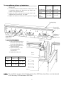
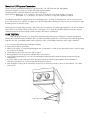
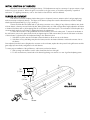
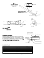
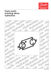
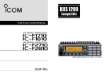
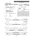
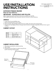
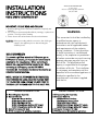
INSTALLATION
INSTRUCTIONS
VIKING RANGE CORPORATION
111 Front Street
Greenwood, Mississippi (MS) 38930 USA
(662) 455-1200
VGBQ SERIES CONVERSION KIT
IMPORTANT: PLEASE READ AND FOLLOW
1. Before beginning, please read these instructions completely and
carefully.
2. Do not remove permanently affixed labels, warnings, or plates from
product. This may void the warranty.
3. Please observe all local and national codes and ordinances.
CAUTION: Before proceeding with the conversion, shut off the gas
supply to the appliance prior to disconnecting the
electrical power.
GAS CONVERSION
To convert a grill from natural to LP/Propane gas or
LP/Propane to natural, you must use the conversion kit
supplied by the manufacturer. When converting to
Natural Gas, use the NK-VGBQ conversion kit. When
converting to LP/Propane, use the LPK-VGBQ
conversion kit. Conversions should only be done by an
authorized service technician.
NOTE: WHEN THE CONVERSION IS COMPLETED,
THE CONVERSION LABEL MUST BE PLACED NEXT
TO THE RATING LABEL UNDER THE DRIP TRAY IN
THE REAR LEFT CORNER NEXT TO THE INLET PIPE.
NK-VGBQ Conversion Kit Part List
(1) Natural Regulator Assembly
(1) Natural Orifice Kit
(4) #40 Grill Burner Orifices
(1) #58 Smoker Burner Orifice
(2) #49 Side Burner Orifies
(2) #51 Infrared Burner Orifices (15” burner)
(1) #49 Infrared Burner Orifice (20” burner)
(1) Natural Conversion Kit Label
(1) F1710 Conversion Kit Installation Instructions
WARNING
This conversion kit shall be installed by
a qualified service agency in
accordance with the manufacturer’s
instructions and all applicable codes
and requirements of the authority
having jurisdiction. If the information
in these instructions is not followed
exactly, a fire, explosion or production
of carbon monoxide may result causing
property damage, personal injury or
loss of life. The qualified service
agency is responsible for the proper
installation of this kit. The installation
is not proper and complete until the
operation of the converted appliance is
checked as specified in the
manufacturer’s instructions supplied
with the kit.
LPK-VGBQ Conversion Kit Part List
(1) LP/Propane Regulator Assembly
(1) LP/Propane Orifice Kit
(4) #53 Grill Burner Orifices
(1) #74 Smoker Burner Orifice
(2) #57 Side Burner Orifices
(2) #63 Infrared Burner Orifice (15” burner)
(1) #57 Infrared Burner Orifice (20” burner)
(1) LP/Propane Conversion Kit Label
(1) F1710 Conversion Kit Installation Instructions
To convert grill burners, side burner and smoker burner:
1. Remove all grates, flavor generators and stainless steel burners
from the unit.
2. Look into the burner box back toward the control panel in order
to located the orifice hoods. Remove the gas orifice hoods
located on the grill burner valves.
3. Replace the orifice hoods with the correct gas orifice hoods
supplied in the conversion kit. (See chart)
4. Replace the stainless steel burners, flavor generators and grates.
Natural
LP/Propane
Orifice Hood Orifice Hood
Grill Burners
Smoker
Burner
(4) - #40
(4) - #53
(1) - #58
(1) - #74
Side
Burners
(2) - #49
(2) - #57
Landing ledge
Rear side of
control panel
Grill Burner /
Side Burner
Orifice hoods
Smoker Burner
Orifice hood
To convert the infrared burner:
1. Remove the back cover from
the unit to expose the orfice
hood to the infrared burner.
2. Remove the gas orifice hood
located on the grill.
3. Replace with the gas orifice
hood supplied in the
conversion kit.
4. Replace the back cover
Infrared
Burner
Orifice hood
Back
Cover
Natural
LP/Propane
Orifice Hood Orifice Hood
15”
(2) - #51
(2) - #63
20”
(1) - #49
(1) - #57
NOTE: For installation in areas with altitudes greater than 2000 feet, the orifices must be derated
at 4% for every 1000 feet above 2000 feet.
2
Natural or LP/Propane Connection
Fixed Connection: Standard Residential 1/2” gas service line - 1/2” NPT male with 3/8” flare adapter.
LP/Propane Cylinder Connection: 1/2” NPT male with 3/8” flare adapter
Operating Pressure: 4.0 W.C.P. Natural or 10.0” W.C.P. LP/Propane
Supply Pressure: Natural gas - 6” to 14” W.C.P. If in excess of 14” W.C.P., a step down regulator is required.
LP/Propane - 11” to 14” W.C.P. If in excess of 14” W.C.P., a step down regulator is required.
The installer must check the supply pressure and operating pressure. To check operating pressure, remove one burner and
hook a manometer to the orifice hood. Ignite one of the remaining burners and turn the valve for the removed burner to high.
Read the pressure on the manometer.
Check with your local gas utility company or with local codes for instructions on installing gas supply lines. Be sure to check on
type and size of run, and how deep to bury the line. If the gas line is too small, the unit will not function properly. Any joint
sealant used must be an approved type and be resistive to the actions of natural gas.
LEAK TESTING
Although all gas connections on the grill are leak tested at the factory prior to shipment, a complete gas tightness
check must be performed at the installation due to possible mishandling in shipment or excessive pressure unknowingly being
applied to the unit. Periodically check the whole system for leaks, or immediately check if the smell of gas is detected.
1. Do not smoke while leak testing. Extinguish all flames.
2. Never leak test with an open flame.
3. Make a soap solution of one part liquid detergent and one part water. You will need a spray bottle, brush or towel to apply
the solution to the fittings.
4. Check that all control knobs are in the “OFF” position.
5. Blowing bubbles in the soap solution indicates that a leak is present.
6. Stop a leak by tightening the loose joint or by replacing the faulty part with a replacement part recommended by the
manufacturer.
7. If you are unable to stop a leak, shut off the gas supply and call an authorized gas appliance service technician or
LP/Propane gas dealer. Do not use the grill until the leak is corrected.
8. After checking for leaks, push in and turn any control knob to release the pressure in the hose and manifold. Turn off the
control knob.
Leak Test Points
3
INITIAL IGNITION OF BURNERS
All burners are tested before leaving the factory. Field adjustments may be necessary for proper mixture of gas
and air for proper operation. When the grill is connected to the gas service, it should be adjusted by a qualified
technician. For lighting instructions, refer to the Outdoor Gas Grill Use and Care Manual.
BURNER ADJUSTMENT
Each burner is tested and adjusted at the factory prior to shipment; however, variations in the local gas supply may
make it necessary to adjust the burners. The flames of the burners (except the rotisserie infrared burner) should be visually
checked and compared with Fig. 1, Fig. 2, and Fig. 3.
Flames should be blue and stable with no yellow tips, excessive noise or lifting. If any of these conditions exist, check
if the air shutter or burner ports are blocked by dirt, debris, spider webs, etc. With a proper flame height, adjust the air shutter
to obtain a blue flame with no yellow tipping that sits on the burner at the burner ports. The air shutter is locked in place by a
set screw which must be loosened prior to lighting the burner for adjustments.
To access the air shutter on the grill burners and smoker burner, remove the valve panel. To access the air shutter on
the side burners, remove the grates, burner bowls, and grate support. With a screw driver, loosen the lock-screw on the face
of the air shutter. Light the burner and adjust according to the directions below.
1. If the flame is yellow, turn the air shutter counter clockwise to allow more air to the burner.
2. If the flame is noisy and lifting away from the burner, turn the air shutter clockwise to reduce the amount of air to
the burner.
Once adjusted, turn the burner off, tighten the set screw on the air shutter, replace the valve panel for the grill burners and the
grate support, burner bowls, and grates for the side burners.
To ensure proper installation of the grill burners, side burners, and smoker burner:
1. Slide opening in air shutters over the orifice located in the front of the grill.
2. For the smoker burner, secure back of the burner by placing over screw slot on rear of grill and replacing screw.
½”
(1.3 cm)
3
/8”
(.95 cm)
Fig. 1
GRILL BURNER
Orifice
Air
Shutter
4
Fig. 2
SMOKER BURNER
3
/8” (.95 cm)
(If applicable)
¼” (.64 cm)
Distance between ignitor
3
and burner - /16” (.45 cm)
Orifice
Air Shutter
1 1/2”
(3.8 cm)
Air Shutter
3/8” (.95 cm)
Orifice
Fig. 3
SIDE BURNER
(If applicable)
Distance between
ignitor and burner
port - 1/8” (.32 cm)
Spark Ignitor Adjustment
Occasionally a burner may not ignite within a few seconds after
turning the appropriate control knob counter-clockwise. To adjust
the spark ignitor, use a small needle nose plier to turn the metal
head of the ignitor towards the port (opening) on the burner. DO
NOT TURN THE IGNITOR BY THE CERAMIC BASE. This could
cause damage to the spark ignitor.
Metal head
on ignitor
Ceramic Base
BURNER RATINGS
Grill Burners
Smoker Burner
Side Burners
Infrared Burner - 15”
Infrared Burner - 20”
Natural
25,000 BTU
5,000 BTU
15,000 BTU
12,000 BTU
15,000 BTU
LP/Propane
22,500 BTU
3,500 BTU
13,500 BTU
10,500 BTU
13,500 BTU
5
Ports (openings)
on burner
Viking Range Corporation
111 Front Street •Greenwood, Mississippi (MS) 38930 USA•(662) 455-1200
Specifications subject to change without notice.
For more product information, call 1-888-VIKING1 (845-4641), or visit our web site at http://www.vikingrange.com
F1710C
(PS0602VR)