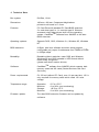
1
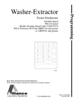
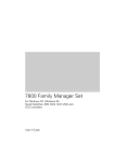
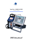
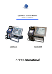
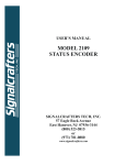
PCBoardCard
ISA-Slot PC Card Drive
for PC
Thank you for deciding to buy an altec product. In order to ensure perfect function and avoid
problems when installing our high-quality German-made product, please read the entire manual
and carefully observe the following points:
•
Observe the general guidelines when handling components or modules which can
be damaged by electrostatic charge or discharge (this applies to the products
described in this manual).
•
If you should encounter any problems during the installation or use of this product,
please contact our service department and ask for advice. If you do not do this, your
guarantee rights may be impaired.
If you have any additional questions, please contact us by telephone or in writing. We will do
our best to help.
Copyright by altec ComputerSysteme GmbH. PCBA5ENG.PM6 02/ 1998. All rights reserved. No
part of this manual may be reproduced, duplicated, transcribed, distributed or translated into
another language without express written permission from altec ComputerSysteme GmbH. The
right is reserved to change specifications without prior notice. All trademarks mentioned are
the property of their respective owners. © altec ComputerSysteme GmbH.
altec ComputerSysteme GmbH disclaims all liability for errors in this manual. Liability for direct
or consequential damages which arise in connection with the use of this documentation is
specifically excluded insofar as this does not contradict the law.
The PC Board Card is manufactured to EMC guideline 89/336/EWG and
is CE certified to EMVG.
Manual Version 1.2 PCBoardCard: ISA-Slot PC Card Drive
1
1. Introduction
1.1
Product description: altec PCBoardCard
The PCBoardCard from altec is a universal ISA-slot card with PCMCIA slots for Type I and II
SRAM, Flash and PC Card ATA memory media (e.g. SanDisk SDP3B-xx) and Type III PC
Card hard disks. It also supports I/O cards such as Fax/Modem and LAN cards. The
PCBoardCARD supports either two PCMCIA type II cards or one PCMCIA type III card.
The BIOS extension (option) avoids the need for extra driver software for PC Card memory
media. Each of the slots can be configured separately with the altec Setup program. The
PCBoardCard can then be accessed like a floppy or hard disk drive (A:, B:, C:, etc.). The
BIOS extension also allows the operating system to be booted from PC Card memory media.
Firmware updates or OEM-specific updates can be downloaded to the card per software
whenever necessary. The operating system (DOS, OS/2) and application software can
also be started directly from the PC Card memory media.
The PCBoardCard is provided with a PowerManager (option) which supports the new 3.3
Volt PC Card technology. 5 Volt and 3.3 Volt PC Cards can be used simultaneously - the
necessary adjustments are carried out by the hardware and software of the PCBoardCard
automatically.
1.2
PCBoardCard Features "Made in Germany"
•
universal PC Card Drive for all Desktop PC with unused ISA-Slot
•
operating system independent, supports MS-DOS, Windows 3.x, Windows 95,
Windows NT, OS/2
•
direct operating system support for Windows 95, Windows NT and OS/2
•
2 PC Card Slots for Type I and II storage media and I/O PC Cards, 1 PC Card Slot
f o r Type III Harddisks
•
the integrated BIOS-Extension allows the use of PC Card storage media without
additional Software and to boot the system from PC Card. The altec Setup menue
allows the individual configuration of the PC Card Slots (A:, B:, C:, etc.), option.
1.3
Extent of delivery
•
ISA-Slot PC Card Drive
•
CardWareTM ( Software (AWARD) inclusive documentation on 3,5" Disk
•
Manual
2. Hard- and Software installation
The PCBoardCard is integrated into the operating system using software or firmware.
Three different installation options are available depending on requirements:
•
For DOS / OS/2, Windows 3.x and Windows 95, the on-board altec BIOS
extension firmware provides a bootable solution for PC Card storage media only
(i.e. SRAM and ATA PC Cards) (see 2.1.2).
•
For DOS and Windows 3.x, the supplied AWARD CardWare software is suitable
for PC Card storage media and for LAN and Fax/MODEM PC Cards (see 2.1.1).
•
Windows 95, Windows NT and OS/2 have built-in PCMCIA support which can be
used to access the PCBoardCard (see 2.2, 2.3 and 2.4). However, for Windows
NT, optional AWARD driver software is recommended since it considerably
improves the handling of exchangeable media under Windows NT.
•
The following sections describe the hardware and software installation in detail.
In case of address conflicts, you can change the base address of the
PCBoardCard as shown in Table 1 (page 4).
2.1
DOS and Win 3.x
This operating system does not have built-in PC Card support. Access to the PCBoardCard
takes place using either the CardWare software from AWARD or the altec BIOS extension
firmware.
2.1.1
Installation/Configuration of the CardWare software
The installation of the CardWare(TM) software from AWARD is described in the AWARD
CardWare manual. If the manual is not available, refer to the file “CARDWARE.WRI” which is
copied to your hard disk by the AWARD installation program. To install the CardWare(TM)
software, insert AWARD Disk 1 in floppy drive A:, switch to drive A: and start the install
program with “INSTALL”. The installation takes place automatically and does not require
further description here.
2.1.2
Installing the altec BIOS extension
a)
Choose a 16 kB region for the BIOS extension in the upper memory area (from
640 kB to 1 MB in main memory) and make sure that no other BIOS uses the
chosen region
Deactivate the shadow RAM option for the chosen region in the PC’s CMOS setup
program
b)
Manual Version 1.2 PCBoardCard: ISA-Slot PC Card Drive
3
c)
d)
If you are using EMM386 or a similar memory manager, exclude this region in the
memory manager call, e.g. for EMM386 the call
DEVICE=EMM386.EXE X=D000-D4000
excludes 16 kB starting at $D000
Configure the base address on the PCBoardCard for the chosen 16 kB region
with jumpers S1-1 to S1-5 (see table 1)
Jumper array S1:boot address setting
Position 6
closed
- Boot option enabled *
open
- Boot option disabled
. . . . . .
. . . . . .
6 5
Base Address
S1C000
C200
C400
C600
C800
CA00
CC00
CE00
D000
D200
D400
Position
54321
00000
0000x
000x0
000xx
00x00
00x0x
00xx0
00xxx
0x000
0x00x
0x0x0
x = open
Base Address
S1D600
D800
DA00
DC00
DE00
E000
E200
E400
E600
E800
0 = closed
Position
54321
0x0xx
0xx00
0xx0x
0xxx0
0xxxx *
x0000
x000x
x00x0
x00xx
x0x00
4
S1
3 2 1
Base Adress
S1EA00
EC00
EE00
F000
F200
F400
F600
F800
FA00
FC00
FE00
Position
54321
x0x0x
x0xx0
x0xxx
xx000
xx00x
xx0x0
xx0xx
xxx00
xxx0x
xxxx0
xxxxx
* = factory setting
Table 1: Jumper array S1
J3 Master/Slave setting:
J3 inserted: Board is Slave (Slot 2 and 3)
J3
(doesn`t work with altec Bootoption!)
J3 not inserted: Board is Master (Slot 0 and 1) *
The altec boot option only supports slots 0 and 1. The AWARD CardWare software
supports slots 0 - 3.
Note: J3 switch only necessary for the use of a second PCBoardCard.
.
Table 2: Jumper array J3
e)
Activate the BIOS extension (boot option) on the PCBoardCard if required with
jumper S1-6
f)
Switch on the PC; when the message
“altec PCBoardCard BIOS Ver “
“press <ALT-S> for setup”
appears, press ALT-S in order to configure the PCBoardCard as required.
2.1.3 Configuration with the altec BIOS Setup program
- If the BIOS extension is enabled, the following message should appear during the POST
(Power On Self Test) of the PC:
“altec PCBoardCard BIOS Ver “
“press <ALT-S> for setup”
If setup is required, press ALT-S to access the altec Setup program in the altec ROMBIOS (Note! the time available to press the key combination can be very short on fast
PC’s). You should then see the configuration screen of the altec Setup program. The
configuration screen is subdivided into three sections and allows a variety of
configuration settings to be made.
.
The current entry field is highlighted. The following key allocation is used within the altec
Setup program:
Cursor Up
Cursor Down
ESC
F10
F6
SPACE
->
->
->
->
go to next entry field
go to previous entry field
exit altec Setup program, changes are not stored
store changes (after a prompt) and
exit altec Setup program
-> set all entry fields to their default value
-> change the value in the currently-active entry field
After exiting the Setup program, the PC is rebooted automatically in order to activate the
changes you have made. The entry fields have the following significance:
A) Section “General Configuration”
-
Display ALT-S Message
Possible values are ENABLED and DISABLED. If you choose ENABLED, the message
“Press
<ALT-S>...” is displayed at boot time during BIOS installation. If DISABLED,
the altec Setup
program can still be called with ALT-S although the message is not
shown.
-
Halt if Error
Possible values are ENABLED and DISABLED. If you choose ENABLED, the message “
Press any key to continue” is displayed at boot time during BIOS installation if the
PCMCIA controller cannot be found.
-
PCMCIA CHIP Base Address
This field is for information only and cannot be changed.
B) Section “Slot 1 (upper) Configuration”
This section is used to configure the upper PCMCIA slot.
-
Disk Emulation
This field specifies which physical drive should be emulated by this slot. Possible values
are DISABLED, A: B: C: D: and Append.
Please note the following:
Manual Version 1.2 PCBoardCard: ISA-Slot PC Card Drive
5
- the operating system can only be booted from this slot if you specify drive A: or drive C:
- if another drive is already present with this drive letter, it will be disabled and can no
longer be accessed.
-
.
-
Memory Base Address
This field specifies at which base address PCMCIA memory cards (e.g. SRAM and
standard FLASH cards) should be mapped. Possible values are C8000h to E0000h in
steps of 4 kB. The rules for choosing this address are the same as for the address of
the BIOS extension.
Note! Ensure that the memory base addresses for slots 1 and 2 lie in the selected
memory area and that the following three configurable ranges do not overlap:
a) BIOS extension: 8 kB
b) Memory range slot 0
4 kB (if enabled)
b) Memory range slot 1
4 kB (if enabled)
I/O Base Address
This field specifies at which base address PC Card ATA-type memory cards should be
mapped. This field cannot be changed at present and is preset to 260h.
C) Section“Slot 0 (lower) Configuration”
This section is used to configure the lower PCMCIA slot. The entry field descriptions are
the same as for slot 1.
Press F10 after specifying all settings in accordance with your requirements. You will
be prompted whether you want to store the changed settings. Press Y to accept
(Please note! On German keyboards press Z instead of Y since the German keyboard
driver is not yet loaded at this stage of booting). After a further prompt, the altec Setup
program then carries out a system restart.
.
2.2 Windows 95
Windows 95 has built-in PC Card support which can be used to access the PCBoardCard.
Alternatively, access can take place using the altec BIOS extension firmware.
2.2.1 Installing the PCMCIA support for Windows 95
a ) Shut down Windows 95, switch off the PC and open the PC’s case.
b ) Deactivate the BIOS extension firmware on the PCBoardCard with the appropriate
jumper and insert the card in an unused 16-bit (long) ISA slot after removing the slot’s
cover plate at the rear of the PC.
c ) Fasten the PCBoardCard with the cover plate screw.
d ) Close the PC’s case, switch on the PC and start Windows 95.
e ) Start the Hardware Assistant as described in the Windows 95 User Manual and search
for new hardware. Confirm the prompt for automatic search with Yes and Next and
choose PCMCIA Socket -> Manufacturer -> Cirrus Logic -> Next.
f ) Follow the prompts of the installation program when required and confirm the prompt to
reboot the computer.
g ) To check for correct installation, open the Control Panel window via START->Settings>Control Panel and double-click the PC Card icon. The status of slot 1 and slot 2 will be
“empty” if no PC Card is inserted.
h ) After inserting a PC Card, you can get information on the inserted card by selecting the
status line with the right mouse button and choosing Properties. PC Card drives should
also be visible in Windows Explorer or in My Computer.
i) If you want to use SRAM PC Cards, edit the CONFIG.SYS file and add the following
lines:
DEVICE=C:\WINDOWS\SYSTEM\CSMAPPER.SYS
DEVICE=C:\WINDOWS\SYSTEM\CARDDRV.EXE /SLOT=2
j) Shut down Windows 95 and reboot the computer
Notes:
•
•
•
•
•
When formatting with the Windows Explorer; the drive to be formatted must not
be selected in the Contents window.
When using SRAM cards; a permanent logical drive is created for each slot: The
permanent logical drive is still displayed even if the card is removed from the slot.
When using ATA cards a temporary logical drive is created for each slot (the next
unused drive letter is used). The temporary logical drive is deleted if the card is
removed from the slot
Some types of SRAM cards cannot be formatted with the Windows Explorer.
Hint: Open an MSDOS window and format with the command format <drive>:\ /u.
It is necessary to inform Windows 95 when you remove a PC Card. This is done
by clicking with the left hand mouse button on the PC Card icon in the Task List (if
activated). Hint: A double-click on the icon opens the PCMCIA Assistant.
2.2.2 Using the altec BIOS extension under Windows 95
The PCBoardCard is installed as described in 2.1.2 an configured as described in 2.1.3.
Notes:
The altec BIOS extension only supports ATA cards, i.e. the disk emulation only
supports C, D or Append. The PC Card must be inserted in either slot 0 or slot 1
before booting the operating system, and must not be removed while the
operating system is running. A new drive letter is created for each inserted PC
Card. The sequence of drive letter creation can be affected by the drive
configuration, since all primary partitions are assigned before assigning the
extended partitions.
2.3 OS/2 Warp3 und Warp 4
OS/2 also has built-in PC Card support which can be used to access Standard Flash and
ATA cards.Alternatively, access can take place using the altec BIOS extension firmware.
Manual Version 1.2 PCBoardCard: ISA-Slot PC Card Drive
7
2.3.1 Installing the PCMCIA support for OS/2
a)
b)
c)
d)
Switch off the PC
Deactivate the BIOS extension firmware on the PCBoardCard with the appropriate
jumper and insert the card in an unused 16-bit ISA slot.
Switch on the PC and start OS/2
Choose System\Control Panel\Adapt installation and install PCMCIA support
as described in the
OS/2 User Manual.
- Select the support for Intel 82365SL-compatible chipsets, i.e. install support for
IBM ThinkPad 750.
- Depending on the type of PC Card(s) used, select PCMCIA Hard Disk and/or
PCMCIA Flash.
Notes:
New drive letters are assigned after the hard disk partitions. This can shift the
drive letters for the CD-ROM and other removable media. PC Cards are installed
as removable media, allowing them to be exchanged without problems while the
operating system is running. One drive is normally created per PCBoardCard slot.
You can also assign several drives per slot for partitioned media with several
partitions (see OS/2 User Manual).
2.3.2 Using the altec BIOS extension under OS/2
The PCBoardCard is installed as described in 2.1.2 an configured as described in 2.1.3.
Add the following line to the CONFIG.SYS file using an editor:
BASEDEV=C:\OS2\BOOT\IBMINT13.I13
Shut down OS/2 and reboot the computer.
Notes:
The altec BIOS extension only supports ATA cards, i.e. the disk emulation only
supports C, D or Append. The PC Card must be inserted in either slot 0 or slot 1
before booting the operating system, and must not be removed while the
operating system is running. A new drive letter is created for each inserted PC
Card. The sequence of drive letter creation can be affected by the drive
configuration, since all primary partitions are assigned before assigning the
extended partitions.
2.4 Windows NT 4.0 Workstation
Windows NT has built-in PC Card support which can be used to access the PCBoardCard.
Alternatively, an optional software product from AWARD can be used. Windows NT is not
compatible with the altec BIOS extension firmware.
2.4.1 Installing the PCMCIA support for Windows NT 4.0 Workstation
a)
Switch off the PC
b)
Deactivate the BIOS extension firmware on the PCBoardCard with the appropriate
jumper and insert the card in an unused 16-bit ISA slot.
c)
Switch on the PC and start Windows NT.
d)
Activate the following services in System Setup in the Devices folder:
Device: PCMCIA
Start mode: Reboot
Device: Atdisk
Start mode: Reboot
e)
Notes:
•
•
.
Shut down Windows NT and reboot the computer.
Due to a peculiarity of this operating system only one slot can be used. A drive
letter is created for both slots, but only one drive can be accessed. The directory
items are mirrored in the second drive.
The sequence of assignment of the drive letters appears to be illogical, but you
can reassign them if necessary with the Hard Disk Manager.
PC Cards are not installed as removable media. Accordingly, they must be
inserted before system boot and must not be removed while the operating system
is running. Warning: Removing or inserting PC Cards while the operating system
is running can cause a system crash.
Special points to observe for SRAM cards:
.
1. Format SRAM cards with the command:
Format <drive>: /t:<no. of tracks> /n:8 /u
Important: Parameter /n (no. of sectors) is hard wired in the BIOS extension
firmware to 8 sectors per track.
2. Calculating the format parameters:
No. of tracks = card capacity [kB] / 8
No. of tracks = card capacity[MB] x 128
Manual Version 1.2 PCBoardCard: ISA-Slot PC Card Drive
9
3. Technical Data
Bus system:
ISA-Bus, 16-bit
Dimensions:
180 mm x 100 mm. Component height above
printed circuit board is 11.8 mm.
Features:
PC Card Drive with standard PC Card BIOS extension.
2 x card slots type II or 1 x card slot type III. Slots are
accessed using either drivers built into the operating
system, CardWareTM Software from AWARD or the altec
BIOS extension.
Operating systems:
Supports DOS, OS/2, Windows 3.x, Windows 95, Windows
NT.
BIOS extension:
8 kByte, with boot software and altec setup program,
configurable per jumper for addresses from C000h to FE00h
in 8 kByte steps.
Bootability:
Bootable without restriction under DOS and Windows;
Windows 95 and OS/2 bootable in HDD format without
media swap recognition.
(please ask about custom drivers).
Software:
CardWareTM software from AWARD which supports both
memory cards and I/O cards (Socket Services und Card
Services).
Power requirements:
5V 150 mA (without PC Card), max. 1A per card slot. 12V is
only required for memory cards which need 12V write
voltage.
Temperature range:
Operation:
Moisture:
Storage:
Moisture:
Firmware update:
The altec BIOS extension firmware can be updated by
software.
0°C to +70°C
0 to 90% (non-condensing)
-40°C to +75°C
0 to 90% (non-condensing)
4. Component placement PCBoardCard
a)
only fitted for boot option (U6, U7, U8, U9, C16, C18,
C20, S1, RN1)
b) only fitted for DMA option (U10, U4, U5,)
c) only fitted for Power Manager (U11, U13)
Manual Version 1.2 PCBoardCard: ISA-Slot PC Card Drive
11