1
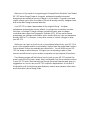
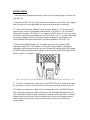
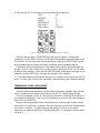
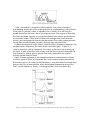
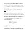
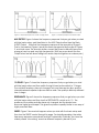
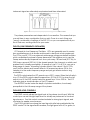
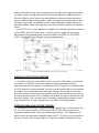
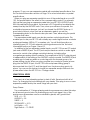
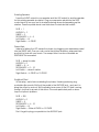
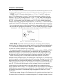
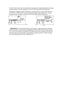
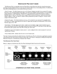
Understanding and using your
moogerfooger®
MF-103 Twelve Stage Phaser
MOOG MUSIC, Inc.
Asheville, NC USA
Welcome to the world of moogerfooger® Analog Effects Modules! Your Model
MF-103 Twelve-Stage Phaser is a rugged, professional-quality instrument,
designed to be equally at home on stage or in the studio. Its great sound and
classic effects come from the state-of-the-art all-analog circuitry, designed and
built under Bob Moog's personal direction.
Your MF-103 is a direct descendent of the original Moog™ modular
synthesizers and professional rack effects. It contains two complete modular
functions: a 6-stage/12-stage voltage-controlled Phaser, and a voltagecontrolled wide range Low Frequency Oscillator (LFO). All four performance
parameters are voltage-controllable, which means that you can use expression
pedals, MIDI-to-CV converter, or any other source of control voltages to 'play'
your MF-103.
While you can use it on the floor as a conventional effects box, your MF-103 is
much more versatile and its sound quality is higher than the single fixed-function
"stomp boxes" that you're probably accustomed to. You will find that your MF103 is a deep musical resource. It will give you an amazing variety of new
sounds and will become your creative companion as you explore its functions.
The following pages will first tell you how to hook up your MF-103 and set the
panel controls for the 'basic' setup. Next, we'll explain how the modular functions
in your MF-103 work. After that we'll go through the panel features and give you
suggestions on how to use your MF-103 in specific applications. At the end of
this booklet you'll find technical specifications, service and warranty information,
and information about Moog Music.
GETTING STARTED
Here are some simple instructions on how you can quickly plug in and try out
your MF-103.
1. Unpack your MF-103. You can place it on a table or on the floor. We suggest
that you place it on a table while you become familiar with its features.
2. Check that the power adaptor has a nominal rating of +9 volts and is also
rated at your country's standard power voltage (120 volts A.C. for the United
States and Canada; 100 volts A.C. for Japan; and 220 volts A.C. for most other
countries). Plug the power adaptor's cord into the MF-103's '+9V' jack. Then plug
the power adaptor itself into a power voltage receptacle. (See Page 13 for
more detailed technical information on power adaptors for the MF-103).
3. Note that the BYPASS light is on. It will light up either red or green. Red
indicates that the MF-103's phaser circuit is off-line (bypassed), while green
indicates that the phaser circuit is on-line. Pressing the 'stomp switch' will toggle
the BYPASS light between red and green. For now, leave the BYPASS light on red.
Refer to Figure 1 for steps 4. and 5.
Figure 1. Basic connections: Instrument to AUDIO IN, monitor amp to AUDIO OUT, and power adaptor to +9V.
4. Connect an instrument cable from the AUDIO OUT jack to a line-level input
on your amp or mixer. Turn the volume control on your amp down but not off.
5. Connect an instrument cable from your signal source to the AUDIO IN jack.
You can feed virtually any instrument-level or line-level signal through your MF103. Examples are guitar, bass, keyboard, theremin, drum machine, or Effects
Send output on your mixer. Play your instrument (or turn on the signal source).
Adjust the volume control on your monitor amp so that the sound level is
comfortable.
6. Now set the MF-103 panel controls as follows (See Figure 2):
RATE
32
AMOUNT
2
SWEEP
5
RESONANCE
0
Left Switch
LO
Right Switch
6-STAGE
Figure 2 - Basic settings for becoming familiar with your MF-103.
Press the stomp switch. The BYPASS light will now turn green. Playing your
instrument, set the DRIVE control so that the LEVEL indicator lights up yellow most
of the time. You will now hear the phaser signal. Adjust the OUTPUT LEVEL control
so the phaser signal is about the same loudness as the bypassed signal.
Continue to play your instrument. Your instrument's signal is going through the
phaser. Listen to how it affects the quality of your instrument's tone. You will hear
a distinct slow variation. Note that the AMOUNT knob changes the strength of the
variation and the RATE knob changes the speed of the variation.
8. In the next sections we'll explain exactly how a phaser works and what the LFO
does. For now, get a feel for the controls by experimenting with different settings.
FREQUENCIES, FILTERS, AND PHASERS
Let's start with some definitions. Please read this section carefully, as it will help
you to understand the basic ideas behind the MF-103 Twelve-Stage Phaser.
Sound is a vibration of the air. The speed of vibration is called the frequency. It
is measured in Hertz (Hz). One Hz is one vibration per second. We hear vibrations
from 20 Hz to 20,000 Hz.
Musical sounds generally have many frequency components. They're called
harmonics, or overtones, or partials. They are what give a sound its characteristic
tone color, or timbre. A graph showing the strength of each of a sound’s
harmonics is called a spectrum. A typical spectrum of a musical sound is shown
in Figure 3.
Figure 3 - Typical spectrum of a musical sound.
A filter, or equalizer, is a signal-modifying device that colors a sound by
emphasizing some parts of the audio spectrum and attenuating (cutting down)
other parts. In general, a filter or equalizer has a ‘quality’ of its own which is
superimposed on the tone color of the original sound. Some types of filters (like
the bass and treble controls on your sound system) have subtle, gentle effects
on a sound’s timbre. Other types of filters have stronger and more dramatic
effects, and are frequently used as vital elements in the music-making process.
Strong filters include phasers, flangers, and wah-type resonant filters.
A graph showing what a filter does is called the filter’s frequency response. The
horizontal axis is frequency. The vertical axis is the filter’s gain. A gain of “1”
(unity) means that, at that frequency, the output of the filter is just as strong as
the input. A gain of less than unity means that the filter’s output is attenuated at
that frequency, while a gain of greater than unity means that the output is
actually greater than the input.
Figure 4 shows examples of the frequency response characteristics of three
common types of filters: (a) a lowpass filter, which passes frequencies without
attenuation up to a so-called ‘cutoff frequency’, and attenuates the frequencies
above cutoff; (b) a resonant filter, which emphasizes frequencies around the
filter’s ‘center frequency’, and (c) a six-stage phaser, which has three dips
Figure 4 - Frequency responses of typical filters: From top, Lowpass Filter; Resonant Filter; and 6-Stage Phaser.
(notches), the middle one of which is at the so-called ‘mid-shift’ frequency. All
three of these filter types are widely used in contemporary music performance.
Each of them has its own distinct sound, a large part of which is directly related
to the shape of its frequency response graph. The first two types are embodied
in the moogerfooger MF-101 Lowpass Filter, while the six-stage phaser happens
to be one of the modes of your MF-103.
PHASER PARAMETERS
The following phaser parameters are under your control in the MF-103:
MODE: 6-STAGE or 12-STAGE, selectable by the right-hand rocker switch.
OUTPUT: AUDIO (main output), or AUX, each with its own output jack.
RESONANCE: Changes the height and sharpness of the frequency response
peaks. Use the RESONANCE panel control and/or the RESONANCE pedal control
jack.
SWEEP: Moves the frequency response pattern through a six-octave range. Use
the SWEEP panel control and/or the SWEEP pedal control jack.
We’ll now use frequency response graphs to show how each of these
parameters affects your MF-103 frequency response. We will always start with
the ‘basic’ panel setup, which is:
AMOUNT: 0 (minimum LFO modulation)
SWEEP: 5 (middle of the range)
RESONANCE: 0 (no resonance)
Right-hand Rocker Switch: 6-STAGE
Output Jack: AUDIO OUT
You may want to experiment with the panel controls and switches as we discuss
each of the parameters.
BASIC SETUP: Figure 5 shows the MF-103’s basic frequency response, the
response that you hear when the panel controls are set up as in the basic setup.
The mid-shift frequency is a little more than two octaves above middle C, and
there are about two-octave intervals between adjacent dips.
Figure 5 – Frequency Response of a ‘basic’ 6-stage phaser.
Figure 6 – Frequency Response of the AUX output.
AUX OUTPUT: Figure 6 shows the frequency response that you get when you start
with the basic setup, and then listen to the AUX Output rather than the Main
AUDIO Output. Note that the frequency response is the opposite of Figure 5.
That is, the peaks of Figure 6 are at the same frequencies as the dips of Figure
5, and vice versa. The sound is similar, except that there is distinctly less sound
energy at very low and very high frequencies. (We’ll say more about the Aux
Output when we talk about using both audio outputs together as a stereo pair.)
Figure 7 – Frequency response of a 12-stage phaser.
Figure 8 – Frequency response of a phaser with high
resonance
12-STAGE: Figure 7 shows the frequency response that you get when you start
with the basic setup and then switch the right-hand rocker switch to 12-stage.
The mid-shift frequency has not changed, but now there are six dips, and the
intervals between adjacent dips are half as wide. The quality is distinctly different
from 6-stage.
RESONANCE: Figure 8 shows the frequency response that you get when you start
with the basic setup and then turn the RESONANCE control up to 10. The
positions of the peaks and dips have not changed, but the peaks have
become higher and sharper. This gives the phaser a quality similar to an array of
highly resonant filters.
SWEEP: Figure 9 shows what happens when you start with the basic setup and
then turn the SWEEP control through its range. Technically speaking, the entire
frequency response moves back and forth horizontally. Musically, you hear the
classic phaser “whooshing” sound as different frequency bands of your
instrument signal are alternately emphasized and then attenuated.
Figure 9 – How the phaser frequency response changes as the SWEEP is varied.
The phaser parameters are independent of one another. This means that you
can set them in any combination that you wish. There is no such thing as a
“wrong” combination of settings of the MF-103, so you can experiment all you
like to find new, exciting effects for your music.
THE LFO (LOW FREQUENCY OSCILLATOR)
LFO stands for Low Frequency Oscillator. LFO’s are generally used to create
slow modulations such as vibrato and tremelo in electronic music equipment.
The LFO in your MF-103 is an extremely wide-range voltage-controlled oscillator
which modulates the phaser’s Sweep parameter. This enables you to vary the
Sweep automatically at speeds from one cycle every 100 seconds (0.01 Hz), to
250 times a second (250 Hz). At the slowest speeds, the change is so subtle and
gradual that it is barely perceptible. At speeds of, say 0.1 Hz to 2 Hz, you get a
wide range of classic “whooshing” phaser effects. From about 2 Hz to 10 Hz,
you’ll find the vibrato and tremelo effects. At frequencies above 20 Hz, the
variation is in the audio frequency range and you get effects similar to ring
modulation.
The RATE control varies the LFO speed over a 250:1 range. When the left switch
is on LO, the RATE control varies the speed from 0.01Hz to 2.5 Hz; when the left
switch is on HI, the RATE control varies the speed from 1Hz to 250 Hz. The LFO
indicator gives a visual indication of the LFO speed.
The AMOUNT control varies the depth of phaser modulation, from barely
perceptible to the full sweep range of the phaser.
THE AUDIO LEVEL CONTROLS
The DRIVE control adjusts the signal level at the phaser circuit input. With this
control you can set the right input level for virtually any instrument or line-level
signal source. Turn this control counterclockwise for strong input signals, and
clockwise for weaker sound sources.
The LEVEL light tells how strong the input signal is after being adjusted by the
DRIVE control. As the signal level increases, the light goes from off, to green, to
yellow, and finally to red. Very weak signals do not light up this light at all. When
the light is green, the signal is below the level that results in audible distortion.
When the light is yellow, some low order distortion may be audible, giving the
sound a subtle warm analog quality. When the signal is strong enough to drive
the light into the red, the distortion at the output becomes stronger and more
distinctly audible. Watch this light when you set the DRIVE control for the desired
effect.
The OUTPUT LEVEL control adjusts the strength of the phaser signals that appear
at the AUDIO and AUX output jacks. Use this control to balance the phaser
signals with the bypassed signal. Note that neither the DRIVE nor the OUTPUT
LEVEL controls affect the strength of the bypassed signal.
Figure 10 – Block diagram of the MF-103 , showing panel controls, switches, and jacks. Pedal/control jacks are not
shown, but performs the same functions as the control knobs.
USING BOTH AUDIO OUTPUTS TOGETHER
If you listen to just the main AUDIO output, or just the AUX output, you will hear
the classic ‘comb filter’ sound that arises from the characteristic phaser
frequency response. However, if you feed the AUDIO output to one speaker and
the AUX output to another speaker, the two outputs together will not have peaks
and dips in the overall frequency response. Instead, some parts of the sound
spectrum will be coming from one speaker and other parts will be coming from
the other speaker. As the LFO modulates the phaser, the sound will seem to swirl
around in space. This is a terrific way of creating a stage-filling ambience from
any sound source. It is also a great way to simulate a rotating speaker.
EXPRESSION PEDALS AND VOLTAGE CONTROL
You now know what each of the rotary control knobs does to the sound of the
MF-103. With the exception of DRIVE and OUTPUT LEVEL, each knob has an
expression pedal/control input which duplicates its effect. This enables you to
plug in up to four expression pedals to play the MF-103 with your feet as well as
with your hands. The moogerfooger EP-1 Expression Pedal is designed for this
purpose. Or you can use expression pedals with equivalent specifications. See
the Technical Information section on Page 14 for more information on pedal
specifications.
When you plug an expression pedal into one of the pedal inputs on your MF103, the pedal adds to the effect of the corresponding control. For example,
let’s say that you plug an expression pedal into your MF-103’s AMOUNT input.
With the pedal all the way back, the amount of LFO signal that modulates the
sweep is set by the AMOUNT knob. Then, when you advance the pedal, the
modulation becomes stronger, just as if you turned the AMOUNT knob up. A
good rule to follow is: when you use an expression pedal, you set the
corresponding knob for the lowest value you want. Then, advancing the pedal
increases that value.
The expression pedal inputs can also be used as control signal inputs. This
enables you to use your MF-103 with virtually any control signal source: modular
analog synthesizers, MIDI-to-CV converters, etc. You will find information on
interfacing your MF-103 with external control signal sources in the Technical
Information section on Pages 14 and 15.
In addition to the four expression pedal inputs, your MF-103 has an LFO output
jack and a SWEEP IN jack. The LFO jack may be used as control or audio signal
sources to control other voltage-controlled devices, including other
moogerfooger analog effects modules. The amplitude of the LFO output signal
is independent of the setting of the AMOUNT control or pedal. The SWEEP IN jack
enables you to feed any audio or control signal to the second group of six
phase-shifting circuits. When you plug a regular two-conductor (mono) phone
plug into the SWEEP IN jack, the MF-103’s second phase shifting group is
disconnected from the LFO, and the signal from the phone plug goes in its
place. You can use this feature to impart two separate sweep motions to the
phaser effect when the MF-103 is in 12-stage mode.
SOME TYPICAL SETUPS
Here are just a few interesting setups to start off with. Experiment with all of
them. Try changing the knob settings with your hands. Then plug in one or more
expression pedals and try the same things with your feet.
Deep Phaser:
The combination of 12-stage phasing and strong resonance makes this setup
an all-around good choice for phattening up any music signal. Any of the
performance parameters can be controlled by pedal, with ‘good effect’.
RATE = 8 – 32
AMOUNT = 5-8
SWEEP = 5
RESONANCE = 8-10
Left Switch = LO
Right Switch = 12-STAGE
Rotating Speaker:
Feed the AUDIO output to one speaker and the AUX output to another speaker
for this rotating speaker simulation. Plug your expression pedal into the RATE
control input to use your foot to simulate slowing down and speeding up the
rotation. Press the pedal about one third down to simulate fast Leslie®.
RATE = 1
AMOUNT = 3
SWEEP = 3
RESONANCE = 6 – 8
Left Switch = HI
Right Switch = 6-STAGE
Phase-Wah:
Instead of letting the LFO sweep the phase, try plugging your expression pedal
into the SWEEP jack. Then you can move the phaser frequency response back
and forth in time with your music. The sweep effect is more noticeable as
RESONANCE is increased.
RATE = doesn’t matter
AMOUNT = 0
SWEEP = 0 – 4
RESONANCE = 0 – 10
Left Switch = doesn’t matter
Right Switch = 6-STAGE or 12-STAGE
RingMod Effect:
In this setup, we’re fast-modulating the phaser, thereby producing ringmodulator-like sounds. We’ll put the pedal in the AMOUNT jack , and use it to
bring the effect in and out. We’ll probably hear some of the LFO itself coming
through, but that’s just part of the effect. This works particularly well on drum
loops or rhythmic patterns.
RATE = 250
AMOUNT = 0
SWEEP = 5
RESONANCE = 6 – 10
Left Switch = HI
Right Switch = Either 6-STAGE or 12-STAGE
Don’t forget to plug your pedal into the AMOUNT jack.
TECHNICAL INFORMATION
NOTE: The following information is intended for use by people who understand analog electronic circuitry
and have enough practical experience to interconnect sophisticated electronic equipment correctly.
POWER: The MF-103 works satisfactorily on +10 to +15 volts DC and uses
about 100 milliamperes of current. Note that most power adaptors that are
rated at +9V DC will actually produce +10 to +11 volts, and power adaptors
rated at +12V DC will actually produce +13 to +14 volts, when used with the
MF-103. For this reason, you can power your MF-103 from virtually any power
adaptor which has a nominal rating between +9 volts and +12 volts at a rated
current of at least 200 milliamperes, and has the appropriate power connector.
If you use a power source other than that which was supplied with the MF-103,
be sure that the voltage never exceeds +15 volts. Power sources with voltages
in excess of +15 volts may cause serious damage to the MF-103's circuit.
Figure 11 – Correct wiring of power supply connector
PEDAL INPUTS: All pedal control input jacks are 1/4" tip-ring-sleeve (stereo)
phone jacks. The sleeves are grounded and the ring terminals are supplied with
+5.7 volts which is current-limited to about 0.5 milliamperes. The tip terminals
receive the variable voltages from the pedals.
An expression pedal for use with the MF-103 should contain a 50KW or 100KW
potentiometer which is connected from the sleeve to the ring terminals. The
potentiometer wiper is connected to the tip terminal. The pedal cable should
be shielded, with the shield connected to the sleeve terminal. See Figure 11.
When connecting one or more pedal control input jacks to a source of
external control voltage such as an analog synth or a MIDI-to-CV converter, you
should use patch cords with tip-ring-sleeve phone plugs. The ring terminal on the
plug should not be connected to anything, so that the MF-103's source of +5.7
volts is not shorted out. Or, if you do not plan to use any expression pedals with
your MF-103 but would like to apply control voltages to one or more pedal
control inputs, you can use patch cords with regular two-conductor phone
plugs. These will short out the +5.7 volt supply to the ring contacts. This voltage is
current-limited, so you won't burn anything out, - but no pedal will work in any of
the pedal control jacks if a tip-sleeve plug is plugged into even one of the
pedal jacks.
Applying a varying voltage to the tip terminal of a pedal control input jack has
the same effect as turning the corresponding knob. A voltage change of about
5 volts at the tip terminal is equivalent to turning the corresponding knob through
its entire range. You can 'program' your MF-103 performance parameters
entirely from external control voltages, by turning all four control knobs (but not
the DRIVE or OUTPUT LEVEL knobs) counterclockwise, and feeding 0 to +5Volt
programming voltages to the tips of the four pedal control input jacks.
Figure 12 – Correct wiring for an expression pedal
Figure 13 – Correct wiring for a TRS CV patch
cable.
AUDIO PATH: The bypassed signal goes through a unity-gain buffer amplifier
and an electronic switch before appearing at the AUDIO and AUX output jacks.
Thus, when the phaser is bypassed, the signal levels at the output jacks are the
same as what your instrument is producing. However, the MF-103 will not pass
an audio signal unless power is applied to it.
LIMITED WARRANTY
Moog Music warrants that its products will be free from defects in materials or
workmanship, and shall conform to specifications current at the time of
shipment, for a period of one year from date of purchase. During the one-year
period, any defective products will be repaired or replaced, at Moog Music's
option, on a return-to-factory basis. This Warranty covers defects that Moog
Music determines are no fault of the user.
RETURNING YOUR MF-103 FOR REPLACEMENT/REPAIR
You must obtain prior approval and an RMA number from Moog Music before
returning any product to us. Wrap your MF-103 carefully and pack it with the
power adaptor in its original carton. The warranty will not be honored if the
product is not properly packed. Then send it to Moog Music (UPS is
recommended) with transportation and insurance charges paid.
A reasonable cost for service and for materials and return freight will be
charged to replace materials defective through the fault of the user, or for
which the one year warranty period has expired.
Transportation and insurance charges from Moog Music to your United States
address, of products repaired or replaced under warranty, will be paid by Moog
Music.
MF-103 SPECIFICATIONS
DESCRIPTION:
Analog effects module incorporating two functions: 6-stage/12-stage phaser,
and wide-range low frequency oscillator (LFO).
FRONT PANEL FEATURES:
RATE rotary control,- varies the LFO’s frequency over a 250:1 range.
AMOUNT rotary control,- adjusts the amount by which the LFO output varies the
phaser sweep.
SWEEP rotary control,- moves the phaser frequency response over a six-octave
range.
RESONANCE rotary control,- adjusts the height and sharpness of the peaks of the
phaser frequency response.
DRIVE rotary control,- adjusts the gain of the audio input to the phaser.
OUTPUT LEVEL rotary control,- balances the phaser signals with the bypassed
signal.
LO-HI rocker switch, which chooses between the low LFO range (0.01Hz to 2.5Hz)
and the high LFO range (1.0Hz to 250Hz.).
LEVEL, a three-color LED that is used to set the DRIVE control.
LFO, a LED that indicates the LFO rate.
BYPASS, a two-color indicator LED that tells whether the phaser is active or
bypassed.
ON/BYPASS, a rugged, smooth-acting ‘stomp switch’.
JACK PANEL FEATURES:
AUDIO IN ¼” phone jack – accepts any instrument-level or line-level signal from
–16 dBm to +4 dBm. Input impedance is one megohm.
AUDIO OUT ¼” phone jack - -4 dBm nominal maximum output level; +8dBm
absolute maximum output level. Output impedance is 5,000 ohms.
AUX OUT ¼” phone jack – 4 dBm nominal maximum output level; +8 dBm
absolute maximum output level. Output impedance is 5,000 ohms.
RATE, AMOUNT, SWEEP, RESONANCE, all of which are stereo ¼” jacks that accept
moogerfooger EP1 (or equivalent) expression pedals, or control voltages from
two-circuit or three-circuit ¼” jacks.
SWEEP IN ¼” phone jack – provides a means of applying an external ±2.5 volt
control signal to the second 6-section phasing circuit, in place of the LFO. Input
impedance is 50,000 ohms.
LFO OUT ¼” jack - delivers the LFO waveform (triangular wave; ± 2.8 volts) for
use by other voltage-controlled devices. Output impedance is 600 ohms.
+9V POWER INPUT jack – accepts standard 9-volt power adaptors
GENERAL SPECIFICATIONS
CASE: Black panel with hardwood sides – classic analog appearance.
DIMENSIONS: 9” x 6” x 2-1/2”
NET WEIGHT: 2 lb
SHIPPING WEIGHT: 4 lb, including power adaptor and instruction manual
POWER REQUIREMENTS: 120 volt, 5W. 220 volt power adaptor available on
special order
MOOG MUSIC Inc. 554C RIVERSIDE DRIVE ASHEVILLE, NC 28801
Phone: (828) 251 0090
FAX: (828) 254 6233
Email: [email protected]
WEB SITE: http://www.moogmusic.com
Entire Contents © 1999, 2003 by Moog Music, Inc.