1
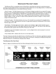
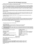
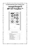
Understanding and Using Your
moogerfooger®
CP-251 Control Processor
Moog Music Inc. Asheville, NC USA
©2000, 2003 by Moog Music Inc.
Welcome to the world of moogerfooger® Analog Effects Modules! Your Model CP251
Control Processor is a rugged, professional-quality instrument, designed to be equally at
home on stage or in the studio. Its great functionality and classic effects come from its
state-of-the-art all-analog circuitry, designed and built under Bob Moog's personal
direction.
Your CP251 is a direct descendent of the original modular Moog™ synthesizers. It
contains a total of eight independent control signal generating and processing
functions. Used with other moogerfoogers, voltage-controlled analog synthesizers, MIDIto-CV converters, or other devices that produce or accept analog control signals, the
CP251 enables you to create an amazing variety of dynamic synthesizer effects.
The following pages will first introduce voltage control, which is the basic technical
principle underlying modular analog synthesizers. Next we'll describe each of the
CP251's eight functions. After that, you'll find a few typical patches, which will give you
some good ideas about how you can use the CP251 with your voltage-controlled gear.
At the end of this booklet you'll find technical specifications, service and warranty
information, and information about Moog Music.
CONTENTS
BASIC THEORY - - - - - - - - - - - - - - - - - - - 3
GETTING STARTED - TOUR OF THE MODULES - 6
USING THE CP251 WITH MF-SERIES DEVICES - 15
TECHNICAL INFORMATION - - - - - - - - - - - 24
WARRANTY INFORMATION - - - - - - - - - - - 27
2
SOME BASIC THEORY
When you first try out an audio processor like a ring modulator or phaser, you plug
your instrument into the AUDIO IN jack, connect the AUDIO OUT jack to your amplifier,
and immediately hear what it does by playing your instrument.
There are no AUDIO IN or AUDIO OUT jacks on the CP251. This is because it is not
designed to process audio (musical sounds). Rather, it processes control signals, those
electrical voltages which act as 'phantom hands', changing the performance
parameters on your voltage-controlled equipment with speed and precision. The use
of control signals to produce interesting musical effects is called voltage control.
We'll begin with a brief discussion of voltage control, followed by a tour of the CP251's
functions. This will provide enough information for you to explore all the features of your
CP251. Then, after the section where we show some useful patches, we'll provide more
detailed technical information for those who are interested.
WHAT IS VOLTAGE CONTROL?
Imagine an oscillator module. An oscillator produces a signal that repeats regularly.
If it repeats between 20 and 20,000 times a second, then we hear it as a pitched tone.
Figure 1 shows a simple oscillator with a signal output jack and a frequency control
knob. The oscillator signal appears at the output jack, and the oscillator frequency may
be varied by turning the knob. The knob on our oscillator is calibrated in Hertz (one Hz.
= one cycle per second). If you feed the oscillator output to an input on your amplifier,
you'll hear a tone whose pitch goes from low to high as you turn the knob clockwise.
Figure 1 - LEFT: Simple oscillator with a signal output jack and a frequency control knob; RIGHT: Waveform that appears
at the OUTPUT jack.
Now imagine that we add a frequency control input jack to the oscillator. You can
apply an electrical voltage to this jack. As you increase the voltage, say from zero volts
to +5 volts, the oscillator frequency increases (See Figure 2). In other words, increasing
the voltage at the frequency control input of the oscillator has the same effect as
turning the oscillator's frequency knob clockwise. You can use either the knob or the
3
control input jack to change the oscillator's frequency, or you can use both together.
We call this kind of oscillator a voltage-controlled oscillator (VCO). The voltage applied
to the frequency control input is called (you guessed it) the frequency control voltage
or, since the pitch that we hear is directly related to the frequency of the oscillator's
signal, the pitch control voltage.
Figure 2 - LEFT: Panel of a simple voltage-controlled oscillator; LOWER RIGHT: Graph showing steps in frequency control
voltage; UPPER RIGHT: Graph showing resulting increase in frequency of output.
In a system of analog synthesizer modules, control signals come from a variety of
sources. For instance, a keyboard produces a series of different voltages, depending
on which key the player depresses. When applied to control a VCO, such a keyboard
pitch control signal produces the pitches of a chromatic scale. Another example is a
low-frequency oscillator (LFO) which produces waveforms with frequencies that extend
below the audio range. When applied to control a VCO, an LFO signal sweeps the
VCO frequency periodically over a range that is determined by how strong the LFO
signal is. If, for instance, we set the LFO frequency to about six times a second, and set
the LFO amplitude (strength) to a small fraction of a volt, the VCO output is a now a
pitched tone with vibrato.
Suppose we want to use both a keyboard and an LFO to control a VCO. That is,
suppose we want to play a scale in which every tone has a vibrato. To accomplish this,
we need to combine the keyboard and LFO signals so that they both affect the
frequency of the VCO. We do this with a mixer module. A mixer for processing control
signals is similar to an audio mixer. They both combine two or more signals. The main
difference between them is that an audio mixer is designed to process frequencies
within the range of hearing. Generally, an audio mixer is not able to process either an
LFO signal or a keyboard signal, because these vary more slowly than audio signals. A
mixer for control signals, on the other hand, is designed to process signals that vary
slowly, or even remain steady. (Technical note: The term for such a mixer is a DirectCoupled Mixer. It is called that because there are no capacitors in the mixer's signal
path to limit its low frequency response.)
Figure 3 shows how we might connect a VCO, an LFO, and a keyboard in a modular
system, to enable the player to produce a chromatic scale with vibrato. The mixer has
two inputs, one of which is equipped with an input level control. The LFO signal is
patched to the mixer input that has the level control, and the keyboard signal is
patched to the mixer input without a level control. The output of the mixer is then
4
applied to the VCO's pitch control input. The mixer in Figure 3 contains a circle with a
"+" in it. This is a way of showing that the two input signals are combined, or added
together. The player adjusts the LFO Frequency (sometimes called Rate) knob to
change the vibrato rate, the Mixer Input Level control to change the amount of vibrato,
and the VCO Frequency control to transpose the pitch range of the keyboard.
Figure 3 - Using a mixer circuit to combine LFO and KEYBOARD control signals. Output of VCO is a series of pitches with
vibrato.
Varying the frequency of an oscillator is just one way to control a module's operation
by means of an externally-applied control voltage. Some other ways are: varying the
gain of a voltage-controlled amplifier (VCA), varying the cutoff frequency of a voltagecontrolled filter (VCF), and varying the attack and decay times of a voltage-controlled
envelope generator (VCEG). In the case of moogerfooger MF-Series Analog Effects
Modules, all performance parameters are voltage-controllable by expression pedals or
externally-applied control voltages.
A wide assortment of signal sources may be used as control voltages. In addition to
LFO's and analog keyboards, commonly-used sources include envelope generators,
envelope followers, sample-and-hold circuits, expression pedals, and MIDI-to-CV
converters. In fact, virtually any source of variable voltage may be used as a control
voltage, including custom-made and homemade control interfaces.
5
GETTING STARTED
We are about to embark on a tour of your CP251's functions. To do this, you'll need
the following items:
• Your CP251,
• A tone generator of some sort, whose frequency is voltage-controlled,
• An expression pedal such as the moogerfooger EP-1,
• Six or eight short (1’-3’) patch cords with ¼” phone plugs,
• A monitor amplifier-speaker.
We’ll feed the CP251’s signals into the tone generator’s frequency control input, and
then listen to how the generator’s pitch changes. This will help us visualize the CP251’s
signals. In the rest of this manual, we’ll use VCTG as an abbreviation for “ Voltage
Controlled Tone Generator” .
What can you use as the VCTG? Here are three candidates:
•Use an analog synthesizer with a pitch control input. The classic Minimoog™ and
Micromoog™ are good examples. Set the instrument so it produces a steady tone at a
pitch of around middle C, and apply the CP251’s signals to the instrument’s pitch
control input.
•Use a moogerfooger MF101 Lowpass Filter. Set MIX to 10, CUTOFF to 250, and
RESONANCE to 10. (These settings cause the filter to oscillate at its cutoff frequency.)
Use the CUTOFF jack as the pitch control input, and patch the filter’s AUDIO OUT to the
input of your amplifier.
•Use the Carrier Oscillator section of a moogerfooger MF102 Ring Modulator. Set the
MF102’s LO-HI switch to HI and the FREQUENCY knob slightly above 120. Use the FREQ.
jack as the pitch control input, and patch the CARRIER OUT jack to the input of your
amplifier.
Setting up for the Tour:
Unpack your CP251. Set it next to your VCTG. Have your supply of short patch cords
handy. Connect an audio cable from the tone generator’s output to your monitor
amplifier’s input. Turn up the amplifier’s gain just enough to verify that you’re getting a
tone.
Verify that your power adapter has a nominal rating of +9 volts. Plug the power
adapter’s cord into either power receptacle on the CP251 (There is a power receptacle
on the back panel, below the moogerfooger trademark, and another receptacle on
the CP251’s bottom panel.) Then plug the power adapter itself into a power voltage
6
receptacle. (See Page 28 for more detailed information on power adapters for the
CP251.) Note that the LED in the LFO section lights up.
Before we begin on our tour, let's look at two of the CP251's features.
Placing your CP-251:
Unlike the moogerfooger MF-Series effects modules, the CP251 is housed in a low
rectangular enclosure. It's designed to be used in conjunction with one or more MFSeries modules and/or other voltage-controlled gear, and to be placed where it is most
convenient. Where you place it in your setup will depend primarily on how you arrange
the rest of your gear. One possibility is to place the CP251 behind your effects
modules, so the patch cords to the modules are short. A second possibility is to place
the CP251 on a table or stand, and run longer patch cords to your voltage-controlled
gear. In this way, you can "play" your CP251 with your hands during performance. A
third possibility is that you can custom-mount your CP251 in an equipment rack. With its
wood end-caps removed, your CP251 is exactly the right size for a 3-unit high, half-rack
space. Note that there is a second +9V power input jack on the CP251's bottom plate,
which can be used when the unit is rack-mounted.
The "Red Jacks"
Eight of the CP251's jacks are held with red nuts. These input jacks are equipped with
power for expression pedals. You can plug an expression pedal directly into any of
these jacks - or use the jacks as conventional inputs. The CP251 jacks with black nuts do
not supply power for expression pedals.
Let's now begin our CP251 tour. We'll begin with the LFO module, which is a control
signal source.
LOW FREQUENCY OSCILLATOR
An LFO (Low Frequency Oscillator) provides repeating waveforms that may be used
for control and timing in voltage-controlled systems. The LFO in your CP251 provides two
waveforms: triangular and square. The output jacks are labeled with graphic symbols
that indicate the waveforms.
The RATE knob varies the speed of the LFO's waveforms over the range of one cycle
every five seconds (0.2 Hz.), to 50 cycles per second (50 Hz.). The LED brightness follows
the triangular waveform, thereby providing a visual indication of the rate. The PEDAL IN
jack is a control input which may be used to voltage-control the LFO rate.
•Connect a patch cord from the LFO's triangular output, to the pitch control input of
your VCTG.
•Set the RATE knob to mid position.
Note that the resulting pitch fluctuation is very wide, usually covering as much as five
7
octaves. Turn the RATE knob slowly to hear the LFO's full speed range.
•Turn the RATE knob counterclockwise.
•Plug an expression pedal into the PEDAL IN jack.
Vary the setting of the pedal to hear its effect on the LFO speed.
Figure 4 - Setup for trying out the LFO module.
ATTENUATORS
An ATTENUATOR cuts down the strength of a signal. Your CP251 has two identical
attenuators, each of which has an input jack, an output jack, and a knob. When the
knob is fully clockwise, the full input signal is available at the output.
•Connect patch cords as follows:
a) From the triangular output of the LFO to the input of one ATTENUATOR,
b) From the ATTENUATOR output to the VCTG pitch control
input.
• Set the knobs as follows:
a) LFO RATE to mid position, and
b) ATTENUATOR full clockwise.
You should hear the pitch vary over several octaves. Now turn the ATTENUATOR knob
counterclockwise. Note that the width of the pitch variation decreases. When the
ATTENUATOR knob is fully counterclockwise, you will not hear any pitch variation from the
LFO signal.
Next, remove the first patch cord from the LFO's triangular output, and plug it into the
8
LFO's square wave output. Turn the ATTENUATOR knob back and forth. Note that the
shape of the effect is determined by the signal that is fed to the ATTENUATOR's input,
and the amount or intensity of the effect is determined by the setting of the
ATTENUATOR knob. This is generally true for all control signal sources and all control
destinations on voltage-controlled devices.
Now we'll illustrate a patch that uses both attenuators.
• Connect more patch cords as follows:
a) from the OUT jack of the second ATTENUATOR, to the PEDAL IN of the LFO.
b) Plug the expression pedal into the IN jack of the second ATTENUATOR.
Set the second ATTENUATOR knob to about "9 o'clock". Now the first ATTENUATOR knob
is varying the strength of the LFO control signal, and the second ATTENUATOR knob is
varying the amount that the expression pedal is changing the LFO rate.
Figure 5 - Setup for trying out the ATTENUATOR modules.
FOUR-INPUT MIXER
A MIXER combines, or adds together, two or more signals. Your CP251's Four-Input
Mixer has four input jacks, labeled 1 through 4. Inputs 1 and 2 have input attenuator
knobs, while inputs 3 and 4 are mixed in without attenuation. The OFFSET knob raises or
lowers the voltage of the mix, while the MASTER knob determines the amplitude of the
entire mix. There are two output jacks, labeled "+" and "-". The "- "output is the negative
of the "+" output. That is, the voltage at the "-" output goes down when the voltage at
the "+" output goes up, and vice versa.
•Connect patch cords as follows:
a) from the LFO triangular output to MIXER input 1,
b) from the LFO square output to MIXER input 2,
c) from the MIXER "+" output to the VCTG pitch control input.
9
• Set knobs as follows:
a) All four MIXER knobs to midposition,
b) LFO RATE to 9 o'clock.
A mixture of triangular and square waveforms will be modulating your tone generator.
Vary the setting of the "1" knob to change the strength of the triangular wave, the "2"
knob to change the strength of the square wave, the OFFSET knob to raise and lower
the waveforms, and the MASTER knob to change the amplitude of the entire mix.
Plug your expression pedal into input 3. Note that the pedal raises and lowers the
waveforms. However, if you plug the pedal into input 4, it won't work, because input 3 is
a red jack and input 4 is not, and only red jacks are equipped to activate an
expression pedal.
Figure 6 - Setup for trying out the Four Input Mixer
LAG PROCESSOR
The Lag Processor provides a means of slowing down a rapidly-changing control
waveform. The RISE knob varies the rate at which the rising part of a waveform is slowed
down, while the FALL knob varies the rate at which the descending part of a waveform
is slowed down.
• Connect patch cords as follows:
a) from the LFO square output to the LAG IN,
b) from the LAG OUT to an ATTENUATOR IN jack,
10
c) from the ATTENUATOR OUT jack to your VCTG pitch control input.
• Set knobs as follows:
a) both RISE and FALL fully counterclockwise,
b) ATTENUATOR knob to midposition,
c) RATE to 9 o'clock.
Note that the waveform sounds perfectly square. Now turn the RISE knob slowly
clockwise. Note that the rising portion of the square wave is being slowed down. Next
turn the RISE knob back to full counterclockwise and the FALL knob slowly clockwise.
Note that the falling portion of the square wave is being slowed down. Experiment with
various combinations of settings of the RISE and FALL knobs. Finally, experiment with the
settings of the RATE and the ATTENUATOR knobs to see their effect. Listen carefully to the
effect of each knob.
Figure 7 - Setup for trying out the Lag Processor.
FOUR WAY MULTIPLE
The FOUR WAY MULTIPLE is a group of four jacks that are connected together. It enables
one control signal source to be sent to more than one destination. One of the jacks is a
red jack, so the control signal source can be an expression pedal. Plug your expression
pedal into the red jack of the FOUR WAY MULTIPLE. The pedal's voltage now appears at
all of the other three jacks.
• Connect patch cords as follows:
11
a) from one of the unused MULTIPLE jacks, to the IN jack of an ATTENUATOR,
b) from the ATTENUATOR OUT jack, to the PEDAL IN jack of the LFO.
These connections enable the expression pedal to control the LFO rate. The rate
range is determined by the setting of the attenuator knob.
• Connect more patch cords as follows:
a) from an unused MULTIPLE jack to INPUT 1 of the MIXER,
b) from the LFO TRIANGULAR output to INPUT 2 of the MIXER,
c) from the MIXER "+" output to your VCTG pitch control input.
Set all the MIXER knobs to mid-position. These connections combine the pedal
voltage with the LFO triangular waveform.
Now step on the expression pedal. Note that the tone rises in pitch and the triangular
modulation speeds up as you depress the pedal. This is because you've used the
MULTIPLE to route the pedal voltage both to the MIXER (where it is combined with the
LFO triangular wave prior to being routed to your VCTG) and through an ATTENUATOR to
the LFO pedal input, where it varies the speed of the triangular wave. Vary the setting of
each of the knobs in the MIXER, the ATTENUATOR, and the LFO to see what effect it has
on the pitch of your VCTG.
Figure 8 - Setup for trying out the Four Way Multiple.
12
NOISE SOURCE
The NOISE SOURCE has a single output jack. It delivers a waveform that is completely
random. When you listen to this waveform directly, you will hear a steady pitchless
"white noise" sound. When you apply the waveform as a control voltage, you will hear
the resultant sound become rough and "static-y".
Temporarily connect the NOISE jack directly to the input of your audio monitor. Note
the distinctive "white noise" quality of the waveform. (NOTE: You can use this waveform
as the audio input of an effects processor such as a moogerfooger MF101 Lowpass
Filter.)
• Connect patch cords as follows:
a) from the NOISE jack to an ATTENUATOR IN jack,
b) from the ATTENUATOR OUT jack to your VCTG pitch control input.
Note that the pitch becomes rough and jagged. The amount of roughness is
determined by the setting of the ATTENUATOR knob.
Figure 9 - Setup for trying out the Noise Source
SAMPLE AND HOLD
The SAMPLE AND HOLD module has two inputs and two outputs. The two inputs are
labeled IN and TRIG. Whenever the TRIG signal crosses a preset threshold, the voltage
at the IN jack is sampled, and is held until the next time the TRIG signal crosses the
threshold. The sampled voltage appears at the OUT 1 jack. In addition, the OUT 1 signal
is fed through a special lowpass filter which smooths the signal out and then delivers it
to the OUT 2 jack. The cutoff frequency of the special lowpass filter is directly related to
13
the LFO rate, so turning the LFO RATE knob affects how smooth the OUT 2 waveform is.
When no patch cord is plugged into the IN jack, the NOISE waveform is bridged to this
jack. When no patch cord is plugged into the TRIG jack, the LFO square waveform is
bridged to this jack.
• Connect patch cords as follows:
a) from OUT 1 to an ATTENUATOR IN jack,
b) from the ATTENUATOR OUT jack to your VCTG pitch control input.
Note that the pitch is changing in random steps at the LFO rate. Vary the setting of the
LFO RATE and ATTENUATOR knobs to vary the speed and amplitude of the control
waveform.
Plug your expression pedal into the IN jack. Move the pedal back and forth. Note that
the setting of the expression pedal, rather than the NOISE waveform, is now being
sampled and held at the LFO rate.
Remove your expression pedal from the IN jack and plug it into the TRIG jack. Move
the pedal back and forth. Note that the NOISE waveform is now being sampled each
time you push the pedal back, rather than at the LFO rate.
Remove the expression pedal from the TRIG jack. Remove the patch cord from the
OUT 1 jack and then insert it into the OUT 2 jack. Note that the resulting signal is a
smoothed version of OUT 1. The rate at which the waveform changes can be varied,
from extremely slow to extremely fast, by changing the setting of the LFO RATE knob.
Figure 10 - Setup for trying out the Sample And Hold Module.
14
USING THE CP-251 WITH OTHER MOOGERFOOGER MODULES
The following examples show a few ways that you can use your CP251 with other
moogerfooger modules. With each example that you try, be sure to experiment with
the settings of all the knobs that you are using. Understand what each knob controls,
and what function each patch cord performs. Try out your own variations. You will be
delighted at the range of effects that you will discover.
Filter Sample and Hold Effects with the MF101 Lowpass Filter
Refer to Figure 11 for the following examples. For all variations, connect your
instrument to the MF101 AUDIO IN jack and your monitor amplifier to the MF101 AUDIO
OUT jack.
Figure 11 - Setup for Filter Sample and Hold examples
15
BASIC SETUP: RANDOM STEP FILTER
• Connect patch cords as follows:
a) Expression Pedal to CP251 LFO PEDAL IN jack.
b) CP251 S+H OUTPUT 1 jack to MF101 CUTOFF jack.
• Set knobs as follows:
a) MF101: AMOUNT “ 0” ; MIX “ 10” ; CUTOFF midposition;
RESONANCE “ 7” .
b) CP251 LFO RATE at about 10 Hz (1 o’clock).
Play sustained tones through the MF101. (Brighter tones yield more audible filter effects.)
Note the random filter effect. Turning up the resonance to filter self-oscillation adds
random stepped tones to the signal. Turn the LFO RATE down and use the expression
pedal to control the speed of the stepping.
Variation 1: Random Continuous Modulation of Filter
Instead of S+H OUT 1, patch S+H OUT 2 to the MF101 CUTOFF jack. The filter cutoff
frequency is now modulated smoothly but randomly.
Variation 2: “ Footsteps”
Same as basic setup, except connect the expression pedal to the S+H IN jack.
Expression pedal sweeps filter cutoff, but in steps that are in time with the CP251 LFO.
Fast, spastic pedal sweeps yield random-like modulation; slow sweeps generate
“ staircase” modulation.
Variation 3: Note-triggered Random Step Filter
• Connect MF101 ENV OUT jack to CP251 S+H TRIG jack
Other connections and settings are the same as for the Basic Setup, except be sure
that MF101 Envelope Speed switch is on SMOOTH, and the DRIVE control is turned up so
the ENV LED lights up bright red every time you play a note. Play a staccato line. The
filter cutoff will change after every note that you play, so each note will have a different
tone color.
Variation 4: Note-Triggered Gliding Step Filter
• Connections are the same as Variation 3 above, except CP251 S+H OUT 2 now goes
to MF101 CUTOFF.
• Settings are the same as the Basic Setup, except CP251 LFO RATE is set to 3 o’clock
(about 22 Hz).
16
Play a staccato line. The filter cutoff will change after every note that you play, so
each note has a different tone color. However, the cutoff glides from one frequency to
the next because of the smoothing action that is associated with S+H OUT 2. Note that
the LFO RATE sets the speed of the glide.
LFO Modulation of the MF101 Lowpass Filter
BASIC SETUP: TRIANGULAR MODULATION OF THE FILTER
• Connect patch cords as follows:
a) LFO Triangular Out jack to ATTENUATOR IN jack,
b) ATTENUATOR OUT jack to MF101 CUTOFF,
c) Expression pedal to LFO PEDAL IN jack.
• Set knobs as follows:
a) CP251 LFO RATE to 0.2 Hz; ATTENUATOR to 5,
b) MF101: AMOUNT “ 0” ; MIX “ 10” ; CUTOFF mid-position; RESONANCE “ 7” .
This patch features triangle wave modulation of the MF101 filter. The attenuator
controls the amount of up and down sweep, the expression pedal and LFO RATE knob
control the speed of the modulation, and the MF101 CUTOFF knob sets the center of
the modulation range.
Variation 1: Square Wave Modulation
Setup is same as above, except the LFO’s Square Wave output is used instead of the
Triangular Wave output. Note the difference in the effect.
Variation 2: Ramp Wave modulation
• Connect more patch cords as follows:
a) LFO Square Wave to LAG IN jack,
b) LAG OUT jack to ATTENUATOR IN jack.
• Set LAG knobs as follows:
a) RISE to “ 0”
b) FALL to” 7”
Using either the expression pedal or the RATE knob, adjust the LFO rate to 2-6 Hz. Note
17
that the rise of the modulation waveform is much faster than the falling part. Now
change to RISE knob to “ 7” and the FALL knob to “ 0” to produce a modulation
waveform in which the falling part is much faster than the rising part.
Experiment with the LAG knobs, the ATTENUATOR knob, and the MF101 CUTOFF and
RESONANCE knobs to explore the different effects that can be achieved by “ playing”
the knobs that affect the modulation waveform.
Figure 12 - Setup for LFO modulation examples.
18
Talking Bass” (A patch that uses both an MF101 Lowpass Filter and an MF102
Ring Modulator)
Figure 13 - Setup for “ Talking Bass” .
• Connect patch cords as follows:
a) MF101 AUDIO OUT to MF102 AUDIO IN,
19
b) Output of your instrument to MF101 AUDIO IN,
c) MF102 AUDIO OUT to input of your monitor amp,
d) Expression Pedal to CP251 LFO PEDAL IN jack,
e) CP251 LFO Square Wave out jack to LAG IN jack,
f) CP251 LAG OUT jack to ATTENUATOR IN jack,
g) ATTENUATOR OUT jack to MF101 CUTOFF jack.
• Set knobs as follows:
a) CP251: LFO RATE low (about 9 o’clock); LAG RISE “ 4” ; LAG FALL “ 7” , ATTENUATOR “ 4” ,
b) MF101: AMOUNT “ 0” ; MIX “ 10” ; CUTOFF mid-position; RESONANCE “ 7”
c) MF102: AMOUNT “ 0” , MIX “ 5” ; FREQUENCY switch “ HI” ; FREQUENCY “ 2 kHz” (about 3
o’clock” ).
Play a bass note. You will hear a voice-like timbre. Changing the CP251 LFO RATE
and/or the expression pedal setting changes the speed at which the voice says “ yeow” .
Experiment with the settings of the LAG RISE and FALL, the MF101 CUTOFF and
RESONANCE, and the MF102 FREQUENCY and MIX knobs.
Dual LFO Modulation
This setup uses your CP251 and an MF102 to illustrate how two LFO waveforms can be
combined to form a dual LFO modulation waveform. One of the LFO waveforms
comes from the CP251’s LFO module, while the other LFO wavefrom comes from the
MF102’s LFO OUT jack. Initially, we’ll listen to the MF102’s CARRIER OUT signal to hear the
modulation.
• Connect the following patch cords:
a) CP251 LFO Triangular Output jack to MIXER IN 2 jack,
b) MF102 LFO OUT jack to CP251 MIXER IN 1 jack,
c) MIXER “ +” OUT jack to MF102 FREQ jack,
d) MF102 CARRIER OUT jack to input of monitor amplifier.
• Set knobs as follows:
a) CP251: All MIXER knobs to midposition; LFO RATE to 11 o’clock,
b) MF102: LFO RATE to “ 0.1” ; AMOUNT to “ 0” ; FREQUENCY to 11 o’clock.
20
Turn down the monitor amp to a comfortable level. You’ll hear frequency modulation
of the carrier oscillator by the two LFO waveforms. MIXER IN 1 and IN 2 determine the
strengths of the individual LFO waveforms, MASTER sets the overall strength of the dual
LFO waveform, and OFFSET raises and lowers the voltage at the center of the dual LFO
waveform, thereby raising and lowering the pitch of the carrier oscillator.
Now disconnect the monitor amp from the CARRIER OUT jack and connect it to the
MF102 AUDIO OUT jack. Connect your instrument the the MF102’s AUDIO IN. Set MIX to
“ 10” and AMOUNT to “ 0” . Listen to the effect of the dual LFO modulation on your
instrument’s ring-modulated signal.
Figure 14 - Setup for dual LFO modulation.
21
“ Phaser-rhythm”
This patch uses the voltage steps at the CP251 S+H OUT 1 jack as the audio input to
an MF103 12-Stage Phaser. The sharp voltage rise at the beginning of each step
creates a wideband click. This causes the phaser to “ ring” simultaneously at several
frequencies, thereby converting the click into a distinctive percussive tone.
Figure 15 - Setup for “ Phaser-rhythm” .
• Connect patch cords as follows:
a) MF103 LFO OUT jack to CP251 S+H IN jack,
22
b) CP251 S+H OUT 1 jack to MF103 AUDIO IN jack,
c) MF103 AUDIO OUT jack to Monitor Amp.
• Set Knobs and Switches as follows:
a) CP251: LFO RATE to 1 o’clock,
b) MF103: AMOUNT “ 0” ; RATE SWITCH “ HI” ; RATE “ 3” (8:30); DRIVE 9 o’clock (so LEVEL light
blinks green and yellow); OUTPUT LEVEL 3 o’clock; SWEEP midposition (“ 5” ), MODE switch
on “ 12-STAGE” ; RESONANCE “ 10” .
You will hear a repeating series of pitched pulses. Each step at the S+H OUT 1 jack
creates one pulse. The pulses vary in loudness. This is because the OUT 1 steps are of
differing heights, which, in turn, is because the MF103 LFO triangular wave is being
sampled, and this waveform is not in exact synchronism with the CP251 LFO. In fact, if
you vary the setting of the MF103 RATE knob, you will hear the loudness pattern of the
pulses change. For now, leave the MF103 RATE knob at “ 3” .
Next, vary the setting of the SWEEP knob. Note that this changes the pitch of the
pulses. Return the SWEEP knob to “ 5” .
Finally, Turn the MF103 AMOUNT knob to “ 5” Now the MF103’s LFO is being sampled
and is modulating the phaser sweep, so each pulse has a different pitch as well as a
different amplitude. Experiment with all four of the MF103 performance parameter
knobs (the larger knobs). Note that the RATE knob determines the syncopation of the
pattern, the AMOUNT knob determines the depth of the pattern, the SWEEP knob
determines the pitch range of the pulses, and the RESONANCE knob determines the
quality of the pulses.
23
TECHNICAL INFORMATION
This section contains technically-oriented information which is somewhat more
detailed than the previous sections . Some users will find this information helpful in
devising advanced uses for the CP251. The information is arranged according to the
CP251 module to which it applies.
MIXER
The nominal input resistance of inputs #1 and #2 is 50KW. The nominal input resistance
of inputs #3 and #4 is 100KW. The nominal output (source) resistance of each of the
outputs is 500 W.
The maximum input-to-ouput gain is unity. The maximum nominal output voltage range
is ±5 volts. The - output is the negative of the + output.
The frequency response of the mixer is DC to 50kHz.
The OFFSET knob can be considered a fifth input with a voltage range of ± 5 volts.
LAG
The nominal input resistance is 10 megW. The nominal output (source) resistance is
500 W.
The nominal input-to-output voltage gain is unity.
Time constants of rising and falling waveform edges are determined by the RISE and
FALL knobs. Nominal time constants are 1 millisecond, 100 milliseconds, and 1 second
when the knobs are fully counterclockwise, in midposition, and fully clockwise,
respectively.
LFO
The nominal input resistance of the PEDAL IN jack is 120 kW. The nominal voltage-tofrequency characteristic of this input is: a one-volt increase doubles the frequency.
The operating frequency of the LFO is determined by the sum of the voltage at the
PEDAL IN jack and the voltage coming from the RATE control. An expression pedal such
as the moogerfooger EP-1 has a nominal range of 0 to +5 volts when plugged into the
PEDAL IN jack. You should use the RATE control to set the minimum desired LFO
frequency, and adjust the voltage range of the pedal or externally-applied control
voltage to get the desired range of LFO frequencies.
The LFO frequency can go both lower than the minimum calibration on the RATE
control (by applying a negative control voltage), and higher than the maximum
calibration on the RATE control (by applying the appropriate positive control voltage).
The minimum frequency is less than 0.03 Hz (one cycle every 33 seconds), and the
24
maximum frequency is greater than 100 Hz.
The nominal peak voltage of the triangular and square waveforms is ±2.5 volts . The
nominal output (source) resistance of each of these outputs is 500 W.
ATTENUATORS
Each of the attenuators is a 50KW, linear taper potentiometer. The IN jack is
connected across the potentiometer element, while the OUT jack is connected from
the counterclockwise end of the element, to the potentiometer’s wiper arm.
FOUR WAY MULTIPLE
The tip terminals of all four jacks are connected together. The sleeve terminals of all
four jacks are connected together.
NOISE
Nominal peak output voltage is ±0.6 volts. Nominal RMS output voltage is 0.17 volts (13 dBm).
Nominal output (source) resistance is 500 W.
Frequency band of the noise waveform is 500 Hz - 3,500 Hz.
SAMPLE AND HOLD
Nominal input resistance at the IN jack is 10KW. Nominal voltage range which this
input will sample is ±3 volts.
Nominal input resistance at the TRIG jack is 10KW. Triggering occurs when the voltage
at the TRIG jack descends through the +1 volt nominal trigger threshold.
Nominal input-to-output gain is unity. If the noise source is sampled, then the output
waveform appearing at OUT 1 is about ±2 volts peak-to-peak. In between samples, the
maximum output voltage drift rate is no more than 0.1 millivolt per second.
The nominal input-to-output gain from the IN jack to the OUT 2 jack is X2. A two-pole
direct-coupled lowpass filter is placed between OUT 1 and OUT 2. The cutoff frequency
of this filter is proportional to the LFO frequency. Thus it is possible to voltage-control this
filter, and to set its cutoff frequency to as low as a small fraction of 1 Hz.
RED JACKS
The CP251 contains a total of eight jacks with red nuts. The Ring terminal of each of
these jacks is supplied with +5.6 volts at a nominal maximum current of 600
microamperes. This is more than adequate to supply operating current to normal
expression pedals. Electronically-inclined users are encouraged to experiment with
25
novel control devices that are powered by the CP251’s red jacks (as well as by any of
the pedal/control jacks on moogerfooger MF-Series products).
Plugging a conventional two-circuit phone plug (tip-sleeve) into any of the red jacks
will not adversely affect the operation of any part of the CP251. Such a phone plug will
short that jack’s pedal supply to ground, causing a current of about 2 milliamperes to
flow through the plug’s barrel.
POWER SOURCE
The CP251 is designed to operate on a conventional +9 volt power adapter with a
current rating of 200 milliamperes or higher. If you wish to use a special power supply, it
should deliver no less than +9.0 volts and no more than +12.0 volts, and have a
current rating of no less than 100 milliamperes.
SELECTING PATCH CORDS FOR USE WITH moogerfooger MF-SERIES MODULES
Your CP251 will work properly with either two-conductor (Tip-Sleeve) or three-conductor
(Tip-Ring-Sleeve) patch cords. If you use two-conductor patch cords, then, as explained
above, plugs inserted into the red jacks will simply short the pedal supply currents to
ground, with no adverse effects whatsoever to the operation of the CP251.
When used with MF-Series devices however, two conductor patch cords will short out
the pedal supply current that is available at all pedal/control input jacks. Thus, if you
plug a tip-sleeve phone plug into one of the pedal/control input jacks of an MF-Series
device, then none of the pedal/control jacks on that device will be able to supply
power to an expression pedal. This is explained in the user’s manual that accompanied
your MF-Series device.
If you wish to use your CP251 Control Processor with an MF-Series device and you wish
to be able to plug one or more expression pedals into the pedal/control jacks of the
device, then your best bet is to purchase or make a set of patch cords with Tip-RingSleeve phone plugs, but do not connect the Ring terminals to anything. Alternately,
you can acquire a set of three-conductor patch cords in which the Ring terminals of
the two plugs of each patch cord are connected together. Such cords will not short out
the pedal supply currents that are available at the MF-Series pedal/control jacks when
the other ends are plugged into most two-conductor phone jacks.
GENERAL CONSIDERATIONS
In general, there is little danger that plugging a patch cord into the wrong pair of
jacks will damage the CP251. However, under certain conditions, shorting an output to
ground or connecting two outputs together may affect the proper operation of the
CP251 circuitry. Two good rules to remember are:
1. You can connect one output to as many inputs as you want, but
2. You should never connect more than one output together. Use a mixer to
combine two or more signals.
26
LIMITED WARRANTY
Moog Music warrants that its products will be free from defects in materials or
workmanship, and shall conform to specifications current at the time of shipment, for a
period of one year from date of purchase. During the one-year period, any defective
products will be repaired or replaced, at Moog Music's option, on a return-to-factory
basis. This Warranty covers defects that Moog Music determines are no fault of the user.
RETURNING YOUR CP-251 FOR REPLACEMENT/REPAIR
You must obtain prior approval and an RMA number from Moog Music before
returning any product to us. (Call 828-251-0090 or email
[email protected] to obtain approval.) Wrap your CP251 carefully and
pack it with the power adaptor in its original carton. The warranty will not be honored if
the product is not properly packed. Then send it to Moog Music (UPS is recommended)
with transportation and insurance charges paid.
A reasonable cost for service and for materials and return freight will be charged to
replace materials defective through the fault of the user, or for which the one year
warranty period has expired.
Transportation and insurance charges from Moog Music to your United States address,
of products repaired or replaced under warranty, will be paid by Moog Music.
MOOG MUSIC, Inc.
554C RIVERSIDE DRIVE
ASHEVILLE, NC 28801
Phone (828) 251 0090
FAX (828) 254 6233
EMAIL: [email protected] or
[email protected]
WEB SITE: http://www.moogmusic.com
Entire contents © 2000,2003 by Moog Music, Inc.
27