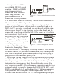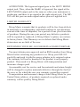
1
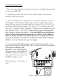
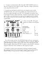
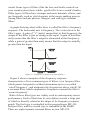
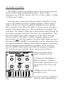
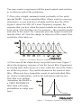
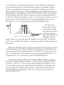
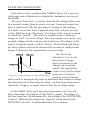
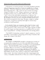
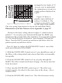
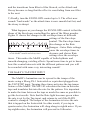
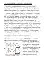
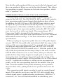
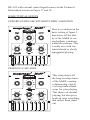
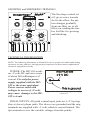
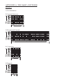
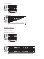
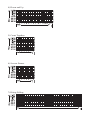
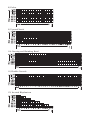
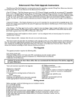
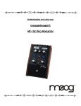
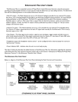
Understanding and Using
Your moogerfooger®
MF-105 MuRF™
TABLE OF CONTENTS
Getting Started............................................3
Frequencies and Filters...............................5
The MuRF’s Filters.....................................7
Envelope Generators.................................10
Sequencers and Pattern Generation..........11
The MuRF’s Animation............................11
The MuRF’s Tap/Step Input.....................13
Audio Level Controls and Mixing............14
Using Both Outputs Together..................14
Expression Pedals and Voltage Control....15
Some Typical Setups.................................16
Technical Information...............................17
Limited Warranty......................................19
MF-105 Specifications.............................20
Appendix A - the MuRF’s Patterns...........22
Welcome to the world of moogerfooger® Analog Effects
Modules! Your model MF-105 MuRF is a rugged, professionalquality instrument, designed to be equally at home on stage or in
the studio. Its great sound and jaw-dropping effects come from
the state-of-the-art analog circuitry, designed and built under Bob
Moog’s personal direction.
Your MuRF is a direct descendent of the original Moog™
modular synthesizers and professional rack effects. It contains two
basic functions: an 8-band array of resonant bandpass filters, and
a pre-programmed “Animation” module that generates sequences
of envelopes that modulate the levels of the 8 filters. Several of
the performance parameters are voltage-controllable, which means
that you can use expression pedals, MIDI-to-CV converter, or any
other source of control voltages, such as other moogerfoogers, to
‘play’ your MuRF.
While you can use it on the floor as a conventional effects box,
your MuRF is much more versatile and its sound quality is higher
than the single fixed-function “stomp boxes” that you’re probably
accustomed to. The MuRF is an astoundingly versatile effects
device, you will find it provides an incredible variety of effects.
You will find that your MuRF is a deep musical resource and will
become your creative companion as you explore its possibilities.
The following pages will first tell you how to hook up your
MuRF and set the panel controls for the ‘basic’ setup. Next, we’ll
explain how the functions of your MuRF work. After that we’ll
go through the panel features and give you suggestions on how
to use your MuRF in specific applications. At the end of this
booklet you’ll find technical specifications, service and warranty
information, information about Moog Music and diagrams of the
MuRF’s Animation patterns.
GETTING STARTED
Here are some simple instructions on how to quickly plug in and
try out your MF-105.
1. Unpack your MF-105. Place it on a table while you become
familiar with its features.
2. Check that the power adaptor has a nominal rating of +9 volts,
providing at least 300 mA (milliamperes) of current and is also
rated at your country’s standard power voltage (120 volts A.C. for
the United States and Canada; 100 volts A.C. for Japan; and 220
volts A.C. for most other countries). Plug the power adaptor’s cord
into the MF-105’s ‘+9V’ jack. Then plug the power adaptor itself
into a power voltage receptacle. Note the MuRF uses a different
power supply than other moogerfoogers, which is only rated at
200mA. Using a 200mA moogerfooger power supply may result
in hum, distortion, and other less than desirable audio artifacts.
Make sure to use the proper power supply.
3. Note that the BYPASS light is on. It will light up either red or
green. Red indicates that the MF-105’s effect is off-line (bypassed),
while green indicates that
the effect is on. Pressing the
‘stomp switch’ will toggle the
BYPASS light between red
and green. For now, leave the
BYPASS light on red.
Refer to Figure 1 for steps 4.
and 5.
Figure 1 - Basic Connections to MuRF
4. Connect an instrument cable from the LEFT/MONO jack to a
line-level input on your amp or mixer. Turn the volume control on
your amp down but not off.
5. Connect an instrument cable from your signal source to the
AUDIO IN jack. You can feed virtually any instrument-level or
line-level signal through your MF-105. Examples are guitar, bass,
keyboard, theremin, drum machine, or Effects Send output on your
mixer. Play your instrument (or turn on the signal source). Adjust
the volume control on your monitor amp so that the sound level is
comfortable.
6. Now set the MF-105 panel
controls as follows (See Figure
2):
PATTERN
ENVELOPE
RATE
MIX
BANK A/B
Filter Sliders 1-8
2
2
6
10
A
All the
way up.
Figure 2 - Basic Settings
Press the stomp switch. The BYPASS light will now turn green.
Playing your instrument, set the DRIVE control so that the DRIVE
indicator lights up yellow most of the time. You will also hear the
filtered signal. Adjust the OUTPUT control so the MuRF’s effected
signal is about the same loudness as the bypassed signal.
7) Continue to play your instrument, playing sustained sounds
like ringing chords. Your instrument’s signal is going through the
MuRF’s filters. Listen to how it affects the quality of your
instrument’s tone. You will hear the level of each of the 8 filters
being turned up and down automatically in sequence by the
Animation at a tempo determined by the RATE control. Note that
changing the ENVELOPE control affects the shape that turns the
filters up and down. The PATTERN rotary switch selects different
patterns that dictate the sequence that turns the Filters up and down
automatically. The MIX control is used to blend the direct sound of
your instrument with the effected sound.
8. In the next sections we’ll explain exactly how the MuRF’s
Filters work and what the Animation does. For now, get a feel for
the controls by experimenting with different settings.
FREQUENCIES and FILTERS
Let’s start with some definitions. Please read this section
carefully, as it will help you to understand the basic ideas behind
the MF-105 MuRF’s filters.
Sound is a vibration of the air. The speed of vibration is called
the frequency. It is measured in Hertz (Hz). One Hz is one
vibration per second. We hear vibrations from 20 Hz to 20,000 Hz.
Musical sounds generally have many frequency components.
They’re called harmonics, or overtones, or partials. They are
what give a sound its characteristic tone color, or timbre. A graph
showing the strength of each of a sound’s harmonics is called
a spectrum. A typical spectrum of a musical sound is shown in
Figure 3.
A filter is a signalmodifying device that colors
a sound by emphasizing
some parts of the audio
Figure 3 - Typical spectrum of a musical sound.
spectrum and attenuating
(cutting down) other parts. In general, a filter has a ‘quality’ of
its own which is superimposed on the tone color of the original
sound. Some types of filters (like the bass and treble controls on
your sound system) have subtle, gentle effects on a sound’s timbre.
Other types of filters have stronger and more dramatic effects, and
are frequently used as vital elements in the music-making process.
Strong filters include phasers, flangers, and wah-type resonant
filters.
A graph showing what a filter does is called the filter’s frequency
response. The horizontal axis is frequency. The vertical axis is the
filter’s gain. A gain of “1” (unity) means that, at that frequency, the
output of the filter is just as strong as the input. A gain of less than
unity means that the filter’s output is attenuated at that frequency,
while a gain of greater than unity means that the output is actually
greater than the input.
Figure 4 - Frequency responses of typical filters.
Figure 4 shows examples of the frequency response
characteristics of two common types of filters: (a) a lowpass filter,
which passes frequencies without attenuation up to a so-called
‘cutoff frequency’, and attenuates the frequencies above cutoff; (b)
a resonant filter, which emphasizes frequencies around the filter’s
‘center frequency’.
Both of these filter types are widely used in contemporary music
performance. Each of them has its own distinct sound, a large part
of which is directly related to the shape of its frequency response
graph. The first type is embodied in the moogerfooger MF-101
lowpass filter, and the second type is embodied in the MuRF..
There are eight separate resonant filters in your MF-105.
The MuRF’s FILTERS
The MuRF’s eight resonant filters have a fixed center frequency,
shown on the legend underneath the filters’ sliders. Their
frequencies are: 200 Hz, 300 Hz, 450 Hz, 675 Hz, 1 KHz, 1.5 KHz,
2.2 KHz, and 3.4 KHz.
Each filter has a slider that adjusts the gain of that filter. In this
respect, the MuRF resembles a graphic equalizer. When a filter’s
slider is all the way down, the gain for that filter is zero, and the
filter’s output is zero. When the slider is all the way up, the filter’s
output is maximum. However – the resemblance to a graphic EQ
ends there. The MuRF’s filters have characteristics that set them far
apart from a graphic equalizer. First, they are resonant filters. They
boost the signal at the center frequencies of the filters. Second,
they are tuned so they don’t overlap. A graphic equalizer will
theoretically not color the signal at all when all the sliders are set to
the same level. The MuRF’s resonant filters on the other hand color
the signal a great deal, adding warm analog resonances at pleasing
intervals through out the frequency spectrum. We’ll now show
how the MuRF’s filters affect your MF-105 frequency response.
We will always start with this ‘basic’ panel setup, which is:
1) Set each of the filters’
sliders to all the way up.
2) Switch the PATTERN to
Bank A, Pattern 1. Pattern 1
turns off the Animation so you
can hear the effect of just the
filters.
3) Make sure the effect is on,
and MIX is at 10.
Figure 5 - Basic Settings for checking out the
filters.
4) Connect just the “left/mono”
output to your amplification.
You may want to experiment with the panel controls and switches
as we discuss each of the parameters.
5) Now, play a bright, sustained sound, preferably of low pitch
into the MuRF - keep in mind that filter effects work by removing
frequencies, so you must have a bright sound to hear the effect!
Figure 6 shows the MF-105’s basic frequency response, the
response that you hear when the panel controls are set up as in the
basic setup. Note that there are 8 resonances – they impart warmth
and color to the sound. For a moment press the bypass switch and
turn the effect off. Note the change in character of the sound. Now
switch the effect back on.
Figure 6 – Frequency Response of MuRF in Basic Setup
6) Now turn all the sliders down except the lowest one. Figure 7
shows the frequency response of just the lowest filter. Experiment
by turning each slider up one at a time, while the rest of the sliders
are all the way down. Pay careful attention to the sound of each
filter. When you have learned the sound of each individual filter,
try various combinations, such as the bottom two and top two.
Note that even without
Animation, the MuRF is
a VERY POWERFUL
filter bank with many
possibilities to sculpt your
tone!
Figure 7 – Frequency response of 200 Hz Filter
7) The Filters’ resonant frequencies can be shifted up and down
by a small amount to create an effect similar to phasing. Figure
8 shows a graph that portrays the results of shifting a resonant
filter’s center frequency. In the MuRF this can be done two ways,
depending on the position of the BANK slider switch. The switch,
located below the PATTERN selector switch is labeled BANK A
or B/LFO. When the slider is in the “A” position, the filters’ center
frequencies can be shifted by an expression pedal (such as the
Moog EP-1) or CV plugged into the LFO/SWEEP Jack.
To hear how
this works, return
to the basic setup
described in Figure
5. Plug a Moog
EP-1 into the LFO/
Figure 8 - Resonant Frequency shift
SWEEP control
input. Then, as you play into the MuRF, rock the EP-1 back and
forth. You will hear the filters’ frequencies shift with the motion of
the pedal.
When the BANK slide switch is in the B/LFO position, an LFO
(Low Frequency Oscillator) shifts the frequencies of the filters as
a group up and down automatically. The LFO is a sine wave. The
rate is determined by the pattern, or an expression pedal (EP-1 or
equivalent) or CV connected to the LFO/SWEEP jack.
To hear the effect of the LFO on the MuRF’s filters, return to
the basic setup outlined in figure 5, then move the BANK slider
switch to “B/LFO”. Now as you play through the MuRF, you’ll
hear the filters swept up and down automatically. To change the
speed of the LFO, plug a Moog EP-1 expression pedal into the
LFO/SWEEP Control Input. The EP-1 can now slow down or
speed up the LFO.
ENVELOPE GENERATORS
Now that we have explained the MuRF’s filters, let’s proceed
with some more definitions to explain the Animation function of
the MuRF.
The term “Envelope” is used to describe the changes that occur
to a musical sound, from its start to its end. A musical sound can
have a rapid onset, like the plucking of a string or the striking
of a drum. It can also have a gradual onset, like a slowly bowed
violin. With the term “Envelope”, the shape of the start of a sound
is called the “Attack”. The end of a sound can have different
shapes as well – it can be abrupt, like on an organ, or it can be very
gradual, fading out like a piano note held down. The shape of the
end of a musical sound is called “Decay”. Both Attack and Decay
are time-related, and can be measured in seconds or milliseconds.
Figure 9 illustrates the components of an envelope.
An “Envelope
Generator” is a circuit
that creates a shape
that corresponds to the
changes in a musical
sound. The signal that
comes out of an Envelope
generator is sent to a
Figure 9 - a representation of a Volume Envelope
control, such as Volume,
and is used to automatically turn up and down that control to shape
the start and end of that musical sound. An Envelope Generator is
started by a trigger - a signal used to start the envelope shape.
In the MuRF, there are 8 Envelope generators, one for each
filter, that shape the Volume of that Filter’s signal. The shape of
the Envelopes are all determined by the setting of the ENVELOPE
Control. When the Envelopes are started is determined by the
PATTERN selected. To understand that, let’s continue.
SEQUENCERS and PATTERN GENERATION
A Sequencer is used to generate reoccurring rhythmic patterns,
often by triggering sequences of notes in synthesizers or drum
machines. However sequencers can be used for purposes other
than triggering notes - they can be set up to create reoccuring
changes of timbre as well. Vintage sequencers were typically
designed so there were a certain number of “steps”. The term
“step” refers to the individual components of a pattern. For
instance in a bar of music in 4/4 you have four quarter notes. If
the rhythmic activity is no more complicated than quarter notes,
this would correspond to four steps. In many vintage or analog
sequencers, a sequencer typically had eight or sixteen steps
available to build a pattern.
In its simplest form, as a sequencer plays back its steps, each
step can be programmed to send a trigger signal - or not - a step
can be passed over like a musical rest. The trigger signals can then
be used to trigger envelope generators according to the way each
step is programmed - creating a rhythmically reoccurring pattern.
The MuRF’s Animation contains 8 simple sequencers, one for
each filter, each capable of triggering an Envelope Generator that
shapes the volume of the filter.
ANIMATION
The MuRF’s ANIMATION module is designed as a means of
automatically turning the levels of the individual filters up and
down, using envelope generators, according to a pre-programmed
pattern. The ENVELOPE control morphs through different
envelope shapes as you turn it, creating effects that are highly
rhythmic in nature, or are swirling and ethereal. The RATE
control sets the speed of the pattern. The patterns, selected by the
PATTERN selector rotary switch in conjunction with the Bank
slider switch, have been selected to provide a surprisingly wide
variety of rhythmic timbral effects. There are a total of 24 patterns,
arranged in two banks of 12.
An easy way to understand
the Animation is to look at a
simple pattern displayed on
a grid.
Figure 10 shows a
graphic representation of
pattern 2 in Bank A. The
columns going left to right
Figure 10 - Diagram of Pattern 2, Bank A
are the steps of the pattern.
The rows going from bottom to top are the individual filters.
Illustrations of all the Patterns are in Appendix A, page 22.
Return to the basic setting shown in figure 2, which features
pattern 2. As you play your instrument through the MuRF, pay
attention to the sound of the effect and how it corresponds to figure
10. You should hear the Animation “stair-stepping” through the
filters. Turn the RATE control up and down and notice how the
pattern speeds up and slows down.
Now it’s time to explore the ENVELOPE Control - one of the
most powerful parts of the MuRF.
1) With the ENVELOPE Control set at 2, you should hear each of
the filters with a sharp attack and a decay that fades out smoothly
but quickly.
2) Turn the ENVELOPE control to 0 as you play through the
MuRF. The effect sounds much more choppy - the decay time has
been decreased.
3) Now turn the ENVELOPE control up to 5. The effect now
sounds smooth - the attack is the same time as the decay - like a
tremolo effect.
4) Turn the ENVELOPE control to 6. The effect becomes swirly
and the transitions from filter to filter blurred, as the Attack and
Decay become so long that the effect is crossfading from one filter
to the next.
5) Finally, turn the ENVELOPE control up to 8. The effect now
sounds “backwards” as the attack time is now smooth but fast, and
the decay is abrupt.
What happens as you change the ENVELOPE control is that the
shape of the Envelopes controlling the gain of the filters morphs.
Figure 11 shows the changes to the envelope times at different
settings of the Envelope
control. The Envelope times
also change as the Rate
changes - faster Rate settings
cause the envelope times to
Figure 11 - Effect of the ENVELOPE control
decrease and slower Rate
on the MuRF’s attack and decay times
settings slow the envelope
times. This makes the MuRF capable of both rhythmic and
smooth-changing, swirling effects. Spend some time to get to know
how this control interacts with the different patterns and you will
be rewarded with some very interesting sounds!
THE MuRF’S TAP/STEP INPUT
The MuRF’s Animation can be synced to the tempo of the
music using a Moog FS-1 footswitch or equivalent plugged into
the TAP/STEP input. Tapping three times activates the tap tempo
feature of the MuRF. The MF-105 calculates the time in between
taps and translates this into the rate for the pattern. It is important
to make the time between the taps as much the same as possible to
get the best results. Note that the Rate light becomes green when
the rate is set by the Tap input, and returns to red if the RATE
control is changed. The tempo of the Animation is twice the rate
that is tapped on the footswitch. In other words, if you tap in
quarter notes, the Animation will chug along in eighth notes. If you
tap eighth notes, the Animation will proceed in 16th notes.
THE AUDIO LEVEL CONTROLS AND MIXING
The DRIVE control adjusts the signal level at the MuRF’s
circuit input. With this control you can set the right input level
for virtually any instrument or line-level signal source. Turn this
control counterclockwise for strong input signals, and clockwise
for weaker sound sources.
The DRIVE light tells how strong the input signal is after being
adjusted by the DRIVE control. As the signal level increases, the
light goes from off, to green, to yellow, and finally to red. Very
weak signals do not light up this light at all. When the light is
green, the signal is below the level that results in audible distortion.
When the light is yellow, some low order distortion may be
audible, giving the sound a subtle warm analog quality. When the
signal is strong enough to drive the light into the red, the distortion
at the output becomes stronger and more distinctly audible. Watch
this light when you set the DRIVE control for the desired effect.
The OUTPUT control adjusts the strength of the MuRF’s signals
that appear at the LEFT/MONO and RIGHT output jacks. Use this
control to balance the MuRF’s signals with the bypassed signal.
Note that neither the DRIVE nor the OUTPUT controls affect the
strength of the bypassed signal.
USING BOTH AUDIO OUTPUTS TOGETHER
The MuRF has two audio outputs: LEFT/MONO and RIGHT.
When a cable is plugged into just the LEFT/MONO jack, the
output of all filters are sent to
that jack. If a cable is inserted
into the RIGHT jack, then half
of the filters are sent to the
RIGHT output, and half are sent
to the LEFT/MONO output. .
Figure 12 shows the frequency
response of the left and right
outputs when both the left and
right output jacks are used.
Figure 12 – Left and Right Frequency
Response of the MuRF’s Filters
Note that the odd-numbered filters are sent to the left channel, and
the even-numbered filters are sent to the right channel. This allows
for spreading a sound’s frequencies between two speakers, which
adds a “spacious” feel.
EXPRESSION PEDALS AND VOLTAGE CONTROL
You now know what each of the rotary controls does to the
sound of the MF-105. The ENVELOPE, MIX, and RATE controls
have expression pedal/control inputs that duplicate their effects.
In addition, the MF-105 has a LFO/SWEEP input which is used
to adjust the speed of the LFO in Bank B patterns, or to sweep
the frequencies of the filters in Bank A patterns. This enables you
to plug in up to four expression pedals to play the MF-105 with
your feet as well as with your hands. The moogerfooger EP-1
Expression Pedal is designed for this purpose. Or you can use
expression pedals with equivalent specifications. See the Technical
Information section on Page 17 for more information on pedal
specifications.
When you plug an expression pedal into one of the pedal inputs
on your MF-105, the pedal adds and subtracts half the range to the
setting of the corresponding control. For example, let’s say that
you plug an expression pedal into your MF-105’s ENVELOPE
input, with the ENVELOPE control set to 5. With the pedal all the
way in the heel position, the Envelope shape is the same as if the
ENVELOPE control was set to zero. Then, when you advance the
pedal, the Envelope shape begins to morph, just as if you were
turning the knob. At halfway, the pedal equals the setting of the
corresponding control, and at full toe position, it is as if the control
is at 10. A good rule to follow is: when you use an expression
pedal, you set the corresponding knob for the middle value you
want. From the middle of the pedal, advancing to toe position
increases that value, pulling back to heel position decreases the
value.
The expression pedal inputs can also be used as control signal
inputs. This enables you to use your MF-105 with virtually any
control signal source: modular analog synthesizers, MIDI-to-CV
converters, etc. You will find information on interfacing your
MF-105 with external control signal sources in the Technical
Information section on Pages 17 and 18.
SOME TYPICAL SETUPS
UPWARD STAIRCASE WITH RHYTHMIC VARIATION
Here is a variation on the
basic setting of figure 2
that shows off the ability of the MuRF to create rhythmic variations
within the patterns. This
is really nice with sustained chords or slowly
arpeggiated playing.
SWIRLING CASCADES
This setup shows off
the long envelope times
of the MuRF, creating
a shimmering, slowly
evolving timbral landscape for your playing.
This shines on chordal
playing, but also gives
leads an extra something
that makes them stand
out.
GROWING and SHRINKING TREMOLO
The Envelope control set
at 5 gives a nice tremolo
feel to the effect; the pattern changes gradually
from one filter on to all
filters on, making the timbre feel like it is growing
and shrinking.
TECHNICAL INFORMATION
NOTE: The following information is intended for use by people who understand analog
electronic circuitry and have enough practical experience to interconnect sophisticated
electronic equipment correctly.
POWER: The MF-105 works
on +9 volts DC and uses a max
of about 240 milliamperes of
current. Use only the power
supply supplied with the MF105 or the exact equivalent.
Power sources rated with
voltages in excess of +9 volts
may cause damage to the MF105’s circuit.
Figure 13 – Correct wiring of power supply
connector
PEDAL INPUTS: All pedal control input jacks are 1/4” tip-ringsleeve (stereo) phone jacks. The sleeves are grounded and the ring
terminals are supplied with +5 volts which is current-limited. The
tip terminals receive the variable voltages from the pedals.
An expression pedal for
use with the MF-105 should
contain a 50KW or 100KW
potentiometer which is
connected from the sleeve
to the ring terminals. The
Figure 14 – Correct wiring for an expression
potentiometer wiper is
pedal
connected to the tip terminal.
The pedal cable should be shielded, with the shield connected to
the sleeve terminal. See Figure 14.
When connecting one or more pedal control input jacks to a
source of external control voltage such as an analog synth or a
MIDI-to-CV converter, you should use patch cords with tip-ringsleeve phone plugs. The ring terminal on the plug should not be
connected to anything, so that the MF-105’s source of +5 volts is
not shorted out. Or, if you do
not plan to use any expression
pedals with your MF-105 but
would like to apply control
voltages to one or more pedal
control inputs, you can use
Figure 15 – Correct wiring for a TRS CV
patch cords with regular twopatch
conductor phone plugs. These
will short out the +5 volt supply to the ring contacts. This voltage
is current-limited, so you won’t burn anything out, - but no pedal
will work in any of the pedal control jacks if a tip-sleeve plug is
plugged into even one of the pedal jacks.
Applying a varying voltage to the tip terminal of a pedal control
input jack has the same effect as turning the corresponding knob.
A voltage change of about 5 volts at the tip terminal is equivalent
to turning the corresponding knob through its entire range. You
can ‘program’ your MF-105 performance parameters entirely from
external control voltages, by turning the ENVELOPE, MIX, and
RATE control knobs to 5, and feeding 0 to +5 Volt programming
voltages to the tips of the pedal control input jacks. The LFO/
SWEEP jack can also receive 0 to +5 Volt programming voltages.
AUDIO PATH: The bypassed signal goes to the LEFT/ MONO
output jack. Thus, when the MuRF is bypassed, the signal at the
LEFT/MONO output jack is the same as what your instrument is
producing, and there is no signal at the right output jack. The MF105 will not pass an audio signal unless power is applied to it.
LIMITED WARRANTY
Moog Music warrants that its products will be free from defects
in materials or workmanship, and shall conform to specifications
current at the time of shipment, for a period of one year from date
of purchase. During the one-year period, any defective products
will be repaired or replaced, at Moog Music’s option, on a returnto-factory basis. This Warranty covers defects that Moog Music
determines are no fault of the user.
RETURNING YOUR MF-105 FOR REPLACEMENT/REPAIR
You must obtain prior approval and an RMA number from Moog
Music before returning any product to us. Wrap your MF-105
carefully and pack it with the power adaptor in its original carton.
The warranty will not be honored if the product is not properly
packed. Then send it to Moog Music with transportation and
insurance charges paid.
A reasonable cost for service and for materials and return freight
will be charged to replace materials defective through the fault of
the user, or for which the one year warranty period has expired.
Transportation and insurance charges from Moog Music to your
United States address, of products repaired or replaced under
warranty, will be paid by Moog Music.
MF-105 SPECIFICATIONS
DESCRIPTION:
Analog effects module incorporating two functions: 8 – band
Resonant Filter Bank and 24-Pattern Sequencer triggering Volume
Envelopes for 8 Filters.
FRONT PANEL FEATURES:
DRIVE rotary control - adjusts the gain of the audio input to the
effect.
OUTPUT rotary control - balances the level of MuRF’s signal
when the effect is on with the bypassed signal when the effect is
off.
MIX rotary control - adjusts the ratio of direct to effected signal
when the effect is on.
200 Hz – 3.4 Hz slider controls - sets the gain of the 8 resonant
filters.
PATTERN 12-position rotary switch - selects one of 12 animation
patterns.
BANK A, B/LFO slider switch - selects bank of patterns, bank B
patterns include LFO modulation of the filters’ frequencies.
ENVELOPE rotary control - morphs the shape of the patterns’
envelopes.
RATE rotary control - adjusts the rate of the animation patterns
DRIVE, a three-color LED that shows the level of the input signal.
RATE, a LED that indicates the animation pattern rate.
BYPASS, a two-color indicator LED that tells whether the effect is
active or bypassed.
ON/BYPASS, a rugged, smooth-acting ‘stomp switch’.
JACK PANEL FEATURES:
AUDIO IN 1⁄4” phone jack – accepts any instrument-level or linelevel signal from –16 dBm to +4 dBm. Input impedance is one
megohm.
LEFT/MONO OUT 1⁄4” phone jack - -4 dBm nominal maximum
output level; +8dBm absolute maximum output level. Output
impedance is 1,000 ohms.
RIGHT OUT 1⁄4” phone jack – 4 dBm nominal maximum output
level; +8 dBm absolute maximum output level. Output impedance
is 1,000 ohms.
RATE, ENV, LFO/SWEEP, MIX, all of which are stereo 1⁄4” jacks
that accept moogerfooger EP1 (or equivalent) expression pedals, or
control voltages from two-circuit or three-circuit 1⁄4” jacks.
TAP/STEP IN 1⁄4” phone jack – provides a means of syncing the
tempo of the MuRF’s Animation Patterns to the tempo of the music
by pressing on an external footswitch (Moog FS-1, or equivalent)
three times.
+9V POWER INPUT jack – accepts +9VDC unregulated 300 mA
power adapter with positive center.
GENERAL SPECIFICATIONS
CASE: Black panel with hardwood sides – classic analog
appearance.
DIMENSIONS: 9” x 6” x 2-1/2”
NET WEIGHT: 2 lb
SHIPPING WEIGHT: 4 lb, including power adaptor and
instruction manual
POWER REQUIREMENTS: 120 volt, 5W. 220 volt power adaptor
available on special order
MOOG MUSIC Inc. 554C RIVERSIDE DRIVE ASHEVILLE, NC 28801
Phone: (828) 251 0090
FAX: (828) 254 6233
Email:
[email protected]
WEB SITE: http://www.moogmusic.com
APPENDIX A: THE MuRF’s PATTERNS
BANK A
1) No Animation
2) Upward Staircase
3) Downward Cascade
4) Crisscross
5)Tremolo
6) Upward Bounce
7) Brownian Motion
8) Random-like
9)Double Up and Down
10) Downward Band Expansion
11) Polyrhythm
12) Rhythmicon
BANK B - with LFO
1) No Animation
2) Downward Staircase
3) Upward Cascade
4) Down and Up
5) Come Together
6) Seesaw Panner
7) Rising Falling
8) Pulsar
9) Upward Notch
10) Growing and Shrinking Band
11) Double Cascade
12) Inverted Rhythmicon
Notes:
Notes:
©2004 Moog Music Inc.
MOOG MUSIC Inc. 554C RIVERSIDE DRIVE ASHEVILLE, NC 28801
Phone: (828) 251 0090
FAX: (828) 254 6233
Email:
[email protected]
WEB SITE: http://www.moogmusic.com