1
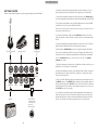
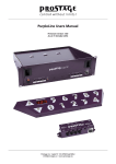
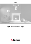
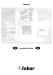
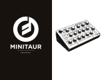
WELCOME TO THE WORLD OF MOOGERFOOGER®
ANALOG EFFECTS MODULES!
Your MF-108M Cluster Flux is a rugged, professional-quality instrument,
designed to be at home on stage or in the studio. Its great sound and jawdropping effects come from state-of-the-art analog circuitry, designed
and handcrafted by our team at MOOG Music in Asheville, North Carolina.
The MF-108M is rooted in the analog wizardry of Bob Moog’s moogerfooger designs. It is a direct descendent of the original Moog® modular
synthesizers and professional rack effects.
Your Cluster Flux offers two basic functions: A dual-range Bucket Brigade
Device (BBD) Delay Line designed for very short delay times and a multiwaveform Low Frequency Oscillator (LFO) capable of modulating the Delay
Line for a variety of effects including Chorus, Flanging and Vibrato.
Several of the performance parameters are voltage-controllable. This means
you can use expression pedals, a MIDI-to-CV converter or any other source
of control voltage, such as other moogerfoogers to play your MF-108M.
In addition, the front panel rotary controls and switches can be controlled
through the use of MIDI and the LFO can be synced to a MIDI Clock.
While you can use it on the floor like a conventional effects box, your
Cluster Flux is much more versatile. Its sound quality is higher than most
fixed-function “stomp boxes” you may be accustomed to. You will find that
your Cluster Flux is a deep electronic musical resource that offers a very
large range of analog sound processing possibilities.
GETTING STARTED
Here are some simple instructions on how to plug in and try your new MF-108M.
1. Unpack your Cluster flux and gently tap the wooden sidepieces of your
new moogerfooger to wake it up after the long journey to its new home.
2. Connect the instrument cable from your sound source to the AUDIO IN jack.
You can feed virtually any instrument or line-level signal through your MF-108M.
3. If you plan on using MIDI, connect a MIDI Cable from the out on the MIDI
controller of your choice to the MF-108M’s MIDI In.
NOTE: The Cluster Flux defaults to MIDI Channel one. Make sure your MIDI controller is
transmitting on MIDI Channel one.
4. Connect an instrument cable from the L/MONO Out jack to a line-level
input on your amp or mixer. Turn the volume control on your amp down but
not off.
5. Using the supplied power adapter, plug the cord into the +9V’ jack. Then
plug the power adapter itself into a power voltage receptacle.
Guitar or Instrument
Power Supply
Expression Pedal
6. Notice that the BYPASS LED is green. This indicates that the MF-108M’s
effect is on. Red indicates that the effect is OFF (bypassed). Make sure the
Cluster Flux effect is off by pressing the BYPASS switch before continuing.
Note: the CLUSTER FLUX requires a +9VDC rated for at least 300 mA. CENTER
POSITIVE power supply
7. Play your instrument (or signal source). Adjust the volume control on your
amplifier so the sound level is comfortable.
AUDIO IN
L/MONO OUT
FEEDBACK
R OUT
TIME
LFO RATE
LFO AMT
FB INSERT
MIX
+9V
300 mA
MIDI IN
MIDI Out from
Computer, MIDI
Controller (like
MP-102), or
Drum Machine
Amplifier
4
8. Set the MF-108M panel controls to the settings shown in figure 1 to explore
the flanging effects of the Cluster Flux, or figure 2 to explore the Chorus
effects of the Cluster Flux.
9. Turn on the MF-108M and play your instrument at its maximum level. Set
the DRIVE control so the DRIVE indicator lights up yellow with the peaks of
the input signal. Adjust the OUTPUT control so the Cluster Flux’s effected
signal is about the same loudness as the bypassed signal. You can also use
the OUTPUT as a boost if you like.
10. Low-pitched, sustaining sounds with a bright timbre will work best to
learn the sounds of your new Cluster Flux. Because the Cluster Flux was
designed with far more range control than traditional Flanger and Chorus
devices, you will discover a much larger palette of tones and effects
5
1. CLASSIC FLANGING
3. VIBRATO
This effect features an up-and-down modulation of the input signal. Some describe it
as a whooshing or jet plane sound.
•Move TIME left to raise flanging frequency
and right to lower it
•Try negative FEEDBACK for a lower pitched,
hollow flange
•For best flanging results MIX control should
be mostly wet
•As RATE increases, try decreasing the
AMOUNT for more musical results
2. CLASSIC CHORUS
This effect features a slight up-and-down
modulation of the input signals’ pitch monitoring only the wet signal.
•Adding FEEDBACK to vibrato gives it a
metallic edge
•The sine wave offers the most natural finger
vibrato sound
•Increasing the RATE modifies the speed of
up and down vibrato. This will also increase
the audible pitch modulation
•As RATE increases, try decreasing the
AMOUNT for more musical results
4. RANDOM FLANGE
This effect features a subtle up-and-down
modulation of the input signals’ pitch. With
a 50-50 mix of wet and dry signal, the result
is a lush, swirling tone.
•Longer TIME settings cause a more audible
pitch modulation
• Adding FEEDBACK to a Chorus effect
gives it a metallic edge
•For best results MIX should be set to
center position
•As RATE increases, try decreasing the
AMOUNT for more musical results
6
This effect features a rhythmic random LFO
step modulation of the flange effect.
•Negative FEEDBACK gives this effect a
deeper and more hollow tone
•The LFO waveform rotary switch set to
random produces a random level each
LFO cycle
•The MIX control should be set to mostly
wet for flange effects
7
5. PEDAL FLANGE
7. RAMP WAVE PITCH MOD
This setup requires an Expression Pedal such
as the Moog EP-2. Pedal Flanging allows
real-time control of the flange frequency
and can be played like a wah-wah effect.
•Connect an EP-2 or other compatible
expression pedal to the TIME control
voltage input
•Set TIME at center position to get full
sweep from the expression pedal
•Negative FEEDBACK gives this effect a
deeper more hollow tone
•Try a little AMOUNT to add modulation to
the pedal flange effect
•The MIX control should be set almost all
the way up for this effect
6. SQUARE WAVE CHORUS
The LFO ramp wave can be used for creative
rhythmic pitch cluster effects. This unusual
effect features a rising modulation of the
pitch followed by a sudden drop.
•Tune the TIME control in conjunction with
the AMOUNT and RATE controls for the
desired range of pitch modulation.
•Adding FEEDBACK will increase retention
of pitch modulation
•Be sure to try the Sawtooth wave with
these settings
•Set MIX to mostly wet
CLUSTER FLUX SIGNAL PATH
The LFO square wave can be used for creative
rhythmic and pitch modulation effects. This
effect features a sudden up-and-down
modulation of the input signals’ pitch, with a
50-50 mix of wet and dry signal.
•Tune the TIME control in conjunction with
the AMOUNT for a harmonic trill effect
•Adding FEEDBACK will increase retention
of pitch modulation with sudden changes
of the square wave modulation
•For best Chorus results, MIX control should
be set to center position
8
9
THE CLUSTER FLUX FRONT PANEL
Any position between the two will blend Wet and Dry signal to the outputs.
DELAY TIME - Sets the length of Delay from the BBD delay line based on
the Range switch setting. In Flange Mode, with AMOUNT set to 0, the delay
time changes from .6 msec to 10 msec nominal. In Chorus mode this change
is 5 msec to 50 msec nominal.
RANGE - Sets the range of delay times available to the DELAY TIME control.
Flange selects a range of shorter delay times while Chorus selects a range
of slightly longer delay times.
DRIVE Control - Sets the input sensitivity of the Cluster Flux. This control
is only active when the Effect is on. The available gain is from -7dB to
+28dB nominal. The Cluster Flux is designed to work with instrument or
line-level signals.
LEVEL LED - Works in conjunction with the DRIVE control. Red indicates
clipping. Yellow indicates the nominal signal level for best signal-to-noise
ratio. Green indicates the presence of signal below the nominal level.
Note: For most instruments, the best approach is to set the DRIVE level so the LEVEL
LED lights up mostly yellow. It is okay to drive the Cluster Flux into clipping/distortion
if that sound is desired. If using an instrument with a wide dynamic range, you may
want to insert a compressor prior to the input of the Cluster Flux for the best signal to
noise ratio without clipping.
OUTPUT LEVEL - Sets the strength of the Cluster Flux Output at both the
Left and Right Audio Outputs. This control is only active when the effect
is on. The Output Level control is designed so a boost, attenuation or no
change can be achieved with any Drive setting.
MIX - Sets the blend ratio of dry to wet signal. This control is only active
when the effect is on. Counterclockwise allows only the dry signal to pass
to the Outputs. Clockwise allows only the wet signal to pass to the Outputs.
10
FEEDBACK - Sets the amount of BBD output fed back into the input of the
BBDs. In Flange Mode, this is used to increase the sharpness and intensity
of peaks in the frequency response of the comb filter. Both Positive and
Negative Feedback are available, with zero feedback at mid-position.
In Flange Mode, Positive Feedback emphasizes all the harmonics of
a fundamental frequency equal to the inverse of the Delay time – For
instance 10 msec Delay creates a comb filter with a fundamental frequency
of 100 Hz and emphasis at 200 Hz, 300 Hz, 400 Hz, 500 Hz, etc. Negative
Feedback shifts the frequency response spectrum down by one octave
which causes only odd harmonics to be emphasized. For instance, a 10
msec delay time with negative feedback creates a comb filter with a
fundamental frequency of 50 Hz and harmonic emphasis at 150 Hz, 250 Hz,
350 Hz, 450 Hz, etc.
In Chorus mode, because the delay time is usually longer than the time
period of the fundamental frequency of the input signal, the difference in
tone between positive and negative feedback is much less noticeable.
WARNING: The Cluster Flux Feedback control is designed to drive the
delay line into self-oscillation. This means the Cluster Flux is capable of
producing a tone without any audio signal present. Tones produced by
self-oscillating feedback may be much stronger than normal signal levels,
so watch your speakers and ears.
Oscillation begins at the 4th indicator lines both left and and right of the
Feedback controls’ mid position.
LFO WAVEFORM - Selects the LFO waveform for modulation of the Delay
Time. There are six waveforms available: Sine, Triangle, Square, Sawtooth,
Ramp and Random Stepped waveforms. Note: that with LFO Amount at
zero, no modulation will be heard.
LFO RATE - Sets the frequency of modulation of the Delay line by the LFO.
The Rate can be varied from .05 Hz to about 50 Hz. The LFO Rate LED
indicates both the rate and waveform of the current LFO settings. The LED
is RED when the Rate is set from the front panel, GREEN when the rate
is set by the Tap Tempo switch, and YELLOW when the LFO is synced to
MIDI clock. When synced to MIDI clock, the Rate control is quantized to
select only rhythmic subdivisions of the MIDI clock tempo.
11
LFO AMOUNT - Sets the overall amount of modulation of the delay time
by the LFO.
Note: As the LFO Amount increases, the functional range of the Delay Time control
is decreased, so that the maximum and minimum delay times are not exceeded.
BYPASS - Used to turn the Effect On and Off. When the effect is On, the
Bypass LED is Green. When the effect is Off, the Bypass LED is Red.
TAP TEMPO - Dedicated switch used for setting the LFO Rate to a musical
tempo. To initiate Tap Tempo control of the LFO, press the Tap Tempo switch
three times with the tempo you want (1/4 notes). On the third press, the
LFO Rate LED will change to Green, and the LFO will change rates to match
the timing of the switch presses. If you continue to press the Tap Tempo
switch, the LFO Rate will be set by a running average of the time between
switch presses. To start over, wait five seconds and then press the Tap
tempo switch three times to set a new tempo. To revert the unit to Panel
control, simply move the LFO Rate control. The LFO Rate LED will light up
Red, and the LFO will set by the panel control.
Note: When the LFO is synchronized to MIDI Clock messages, Tap Tempo is disabled.
MIDI INDICATOR LED - Lights up Red when the unit receives a MIDI message.
Un-implemented MIDI messages do not light up the MIDI LED.
THE CLUSTER FLUX BACK PANEL
AUDIO IN
FEEDBACK
L/MONO OUT
R OUT
TIME
LFO RATE
FB INSERT
LFO AMT
MIX
+9V
300 mA
MIDI IN
AUDIO IN - 1⁄4” unbalanced audio input. The Cluster Flux accepts signals
from Instrument to Line-level.
L/MONO OUT - 1⁄4” unbalanced audio output. When the effect is on, this
output carries the Dry and Wet signal blend set on the front panel Mix
control. The level is determined by the Drive and Output Level controls.
Note: The phase of the Wet signal is not inverted in relation to the Dry signal.
When the effect is off, the input signal passes only through a high-quality buffer on
output in Stereo applications. The default configuration is that the Right
Output carries a mix of the Dry signal plus the inverted Wet signal. When
the outputs are panned hard left and right, this creates a rich stereo effect.
In this mode, when both outputs are mixed together and panned to the
center the wet signal is cancelled. Refer to the section entitled “Output
Configuration” for information on other stereo output modes.
FEEDBACK (FB) INSERT - 1⁄4” TRS jack designed to be used with a standard
insert cable to process the BBD feedback signal path separate from the
Dry signal path. This is an unbalanced, Line-level output and input. The
BBD output signal appears at the tip of the jack, and the return to the
device is applied to the ring of the jack. Because these are line level signals,
some means of attenuation or amplification may be required if using
devices designed for lower signal levels, such as typical guitar stomp-boxes.
FEEDBACK - 1⁄4” TRS jack that can be used with a Moog EP-2 expression
pedal, or a 0V to +5V control voltage on a standard TS cable
To change the feedback from full negative to full positive via control
voltage or expression pedal, set the Feedback control to center position.
TIME - 1⁄4” TRS jack that can be used with a Moog EP-2 expression pedal,
or a 0V to +5V control voltage on a standard TS cable
To change the delay time for a selected RANGE from longest to shortest
via control voltage or expression pedal, set the Delay TIME control to
center position.
LFO RATE - 1⁄4” TRS jack that can be used with a Moog EP-2 expression
pedal, or a 0V to +5V control voltage on a standard TS cable
To use an expression pedal to modify the LFO Rate (05 Hz to 50 Hz) set
the LFO Rate to center position. Rotate the LFO RATE knob counterclockwise.
With a 0V control voltage applied to the LFO Rate CV input, the LFO Rate
can be reduced to half of the minimum panel rate. (.025 Hz) Now rotate
the LFO Rate control fully Clockwise. With a +5V control voltage applied
to the LFO Rate CV input, the LFO Rate can be increased to double the
maximum panel rate. (100 Hz)
LFO AMOUNT - 1⁄4” TRS jack that can be used with a Moog EP-2 expression
pedal, or a 0V to +5V control voltage on a standard TS cable
To modify the LFO AMOUNT from minimum to maximum via control voltage
or expression pedal, set the LFO AMOUNT control to center position
MIX - 1⁄4” TRS jack that can be used with a Moog EP-2 expression pedal,
or a 0V to +5V control voltage on a standard TS cable
To change the Mix from Dry to Wet via control voltage or expression pedal
set the MIX control to center position
its way to the output.
R OUT - 1⁄4” unbalanced audio output. This output can be used as a second
12
MIDI IN - Standard 5-pin DIN for receiving MIDI Messages from another MIDI
device such as a MIDI controller or a computer sequencer.
13
Refer to the MIDI section of this manual for use of the Cluster Flux with
other MIDI devices.
POWER - For connecting to the supplied power adapter
Note: Use only the proper power supply to avoid damage to the device.
Make sure your power supply has the correct Input voltage specifications
for your country:
•120VAC/60 Hz for the US
•230VAC/ 50 Hz for Europe
The output of the adapter is +9VDC and the adapter should be capable of
supplying a minimum of 300mA. The +9VDC is applied to the tip (center)
of a barrel connector plug w/ 5.5mm outer diameter and 2.1mm inner diameter.
The barrel (outside) of the plug is the ground (-).
MIDI CONTROL OF THE MF-108M
The following section explains the MIDI implementation of the Cluster Flux.
For information about what MIDI is and how it works, you can go to the
following webpage for tutorials: www.midi.org/aboutmidi/tutorials.php
MIDI CHANNEL
The default MIDI Channel for the MF-108M is Channel one.
To change this, press and hold both the Tap Tempo and Bypass switches.
While holding both, send a MIDI Channel mode message to the Cluster
Flux on the desired MIDI channel. The MIDI LED will flash green indicating
that the message has been received. The MF-108M will now only receive
MIDI messages on that channel. The current MIDI Input channel is stored in
memory on power down.
CC# 14 (MSB)/ CC#46 (LSB): Mix Control
CC# 12 (MSB)/ CC#44 (LSB): Delay Time
CC# 74: Range (Flange/Chorus) (0-63=Flange, 64-127=Chorus)
CC# 13 (MSB)/ CC#45 (LSB): Feedback
CC# 70: LFO Waveform (0-15=Sine, 16-31=Triangle, 32-47=Square, 48-63=Saw,
64-79=Ramp, 80-95=Random Stepped, 96-127=Smoothed Random (Not
available on Front panel))
CC# 15 (MSB)/ CC# 47 (LSB): LFO Rate
CC# 16 (MSB)/ CC# 48 (LSB): LFO Amount
THE FOLLOWING CC MESSAGES DO NOT CORRESPOND TO FRONT
PANEL CONTROLS, BUT EXTEND THE CLUSTER FLUX’S CAPABILITIES.
The Delay Time Range Multiplier multiplies the delay time by 2, 4 or 8
vastly extending delay time. This feature is for obtaining unusual/ Lo-fi
echo effects. When the delay time is increased past the default maximum
delay time available on the front panel, the BBD Clock signal will be audible
CC# 5 (MSB)/ CC#37 (LSB) Delay Time Portamento. This CC sets the rate
of change of Delay time by all controls (Delay Time control, Delay Time CV,
LFO, and MIDI control of Delay time). Larger values slow down the rate of
change, creating a “glide” effect for the Delay time.The default value on
each power cyle is 0
CC# 75: Delay Time Range Multiplier (0-31=Normal, 32-63= x2, 64- 95=x4,
96-128=x8.
CC# 76: MIDI Sync Enable (0=Disabled, 64=Enabled (default) Disable MIDI
Sync of the Cluster Flux LFO using MIDI Real Time Clock messages. MIDI
Sync is enabled each time the unit is powered up.
CC# 71: LFO Clock Divisions. Here is a list of values and associated rhythmic
divisions achieved with this CC.
Note: MIDI Clock and System Exclusive messages are NOT Channel Mode messages, and are received by the Cluster Flux regardless of the current MIDI Input Channel.
MIDI CONTROL CHANGE (CC) MESSAGES
The settings of the Cluster Flux can be controlled by MIDI Control Change (CC)
messages. In addition to the front panel controls, there are a number of advanced features that can be enabled and edited with Control Change messages.
A MIDI CC message has both a CC# from 0 to 127 and a value from 0-127.
The CC values that affect panel controls replace the physical setting of
the front panel controls. When the corresponding front panel control is
changed after receiving a MIDI CC message, the value will return to that
panel control.
CC#71 VALUE
CLOCK DIVISION
CC#71 VALUE
CLOCK DIVISION
0-5
1/32 Triplet
66-71
Dotted 1/4
6-11
1/32 Note
72-77
1/2 Note
12-17
1/16 Triplet
78-83
Whole Triplet
18-23
1/16 Note
84-89
Dotted 1/2
24-29
1/8 Triplet
90-95
Whole Note
30-35
Dotted 1/16
96-101
Whole + 1/4
36-41
1/8 Note
108-113
Dotted Whole
42-47
1/4 Triplet
108-113
WH+Dotted 1/2
control will result in conflicting values.
48-53
Dotted 1/8
114-119
2 Whole Notes
THE FOLLOWING CC MESSAGES CORRESPOND TO PANEL CONTROLS:
54-59
1/4 Note
120-125
3 Whole Notes
60-65
1/2 Triplet
126-127
4 Whole Notes
Note- Moving a panel control while receiving MIDI CC messages for that same
CC# 91: Bypass On/Off (0-63=Effect Off 64-127=Effect On)
CC# 7 (MSB)/ CC#39 (LSB): Output Level Control
14
CC# 72: LFO Phase Reset- Sending any value of this CC message will restart
15
the LFO from the beginning of its waveform.
CC# 73: Enable LFO Note Reset (0=Disabled, 64=Enabled) Enable or disable
the restarting of the LFO from the beginning of its waveform when the unit
receives a MIDI Note On message. When changed, the value is stored to
memory when the unit is powered down. Default is disabled
CC# 77 Enable MIDI Note mode (0=Disabled, 64=Enabled (default)Enable/Disable MIDI notes setting the delay time of the unit. Each time the
unit is powered on it defaults to enabled.
CC# 78 Enable MIDI Note Spillover mode (0=Disabled (default), 64=Enabled)
Allows MIDI Notes to act as a momentary bypass switch. When enabled, a
MIDI Note On message turns the effect on. A MIDI Note Off message stops
audio from entering the effect, but does not disable monitoring of the
effect signal. When combined with enough Feedback, this mode can be
used to rhythmically “punch in” ringing comb filter or lo-fi delay effects.
MIDI NOTE MODES - The Cluster Flux delay time can be controlled from MIDI
Note On messages. Tuned comb filter effects using the Flange or Chorus mode
can be played from a keyboard or sequencer. When this mode is enabled the
unit receives a MIDI “Note On” message. The “Note ON” number determines
the Delay time. The unit responds to MIDI note numbers 0 to 90. The MIDI Note
On Velocity value is ignored.
MIDI CLOCK SYNC - The LFO can be synchronized to MIDI System Real-time
Clock messages. These messages are 24 ppq messages that can be sent via
MIDI computer sequencers or from drum machines. To enable the sending of these messages, consult the user manual for your MIDI device. When
the Cluster Flux receives MIDI Clock messages, the LFO LED turns Yellow to
indicate that it is synchronized to the MIDI Clock tempo. When the LFO is
synchronized to a MIDI Clock tempo, the LFO can be set to divisions of this
tempo. This is either from the front panel LFO Rate control, or from MIDI CC# 71.
OUTPUT CONFIGURATION
The Right Output of the Cluster Flux is shipped from the factory having a Mix
of Dry signal and phase inverted Wet signal from the output of the BBDs. This
is so the left and Right outputs can be panned hard left and right for a very
nice stereo effect. The Right output can be configured in other ways with the
DIP switches located on the Circuit board of the unit.
Any damage that occurs to the unit while changing the configuration from
the factory setting is not covered under the Warranty.
The bottom of the unit can be taken off by removing the four screws and
rubber feet. The Output DIP Switch offers four configurations as illustrated
DEFAULT OUTPUT CONFIGURATION: RIGHT OUTPUT & MIX ENABLED;
WET SIGNAL OUT OF PHASE
6
5
4
3
2
1
RIGHT OUTPUT & MIX ENABLED; DRY SIGNAL OUT OF PHASE
6
5
4
3
2
1
RIGHT OUTPUT DRY & MIX DISABLED; WET SIGNAL IN PHASE
6
5
4
3
2
1
MIDI SysEx MESSAGES - used for updating or finding out the units’ firmware
version. For more information about this, refer to user notes with any firmware
updates posted in the Cluster Flux section of the moogmusic.com website
PEDAL INPUTS
RIGHT OUTPUT DRY & MIX DISABLED; WET SIGNAL OUT OF PHASE
All pedal control input jacks are 1/4” tip-ring-sleeve phone jacks. The sleeve
is grounded and the ring terminals are supplied with +5 volts which is currentlimited. The tip terminals receive the variable voltages from the pedals.
An expression pedal for use with the MF-108M should contain a 50KOhm
or 100KOhm linear taper potentiometer.
Applying a varying voltage to a pedal control input jack has the same
effect as turning the corresponding knob. With the panel controls set to
mid-position, a voltage change of about 5 volts is equal to turning the
corresponding knob through its entire range.
Note that with the Cluster Flux, you may use standard TS cables for control
voltages at the same time as Expression pedals.
16
6
5
4
3
2
1
Note: Do not set the Output configuration switch to any settings other than these
17
APPENDIX: SPECIFICATIONS
The Cluster Flux is a 100% analog signal path delay device with two NOS, high
voltage BBDs tuned for optimum response in the Chorus and Flange times. It
features extensive time modulation and MIDI capabilities.
FRONT PANEL
•TIME: Adjust delay time 0.6mS to 10mS in Flange mode and 5mS to 50mS
in Chorus mode.
•RANGE: Select between Flanger and Chorus mode
•FEEDBACK: Continuous control from no feedback to infinite feedback.
Bi-Polar control allows the feedback to highlight even or odd harmonics.
•DRIVE: Allows between -7dB and +28dB of gain or attenuation of the input
signal for optimum signal path, level matching and distortion sounds.
•OUTPUT: Allows gain and attenuation of output signal for compatibility with
a wide range of input devices.
•MIX: Cross fader control to vary the amount of wet or dry signal heard on output.
•LFO: Six position rotary switch to select the LFO wave shape for delay
time modulation. Select between Sine, Triangle, Square, Ramp, Saw and
Random stepped modulation.
•LFO RATE: Adjust the LFO rate from the sub audio to audio rates. Control
from 0.05 Hz to 50 Hz from the front panel (more from the CV).
•LFO AMOUNT: Controls the amount of LFO modulation of the delay time.
LIMITED WARRANTY
Moog Music warrants that its products will be free from defects in materials
or workmanship, and shall conform to specifications current at the time of
shipment, for a period of one year from date of purchase. During the one-year
period, any defective products will be repaired or replaced, at Moog Music’s
option, on a return-to-factory basis. This Warranty covers defects that Moog
Music determines are no fault of the user.
LEDS AND SWITCHES
•RATE: A Bi-Color LED to display the rate and shape of the LFO wave as well
as the source of control.
•MIDI: A Bi-Color LED to display the presence of MIDI control.
•LEVEL: A Bi-Color LED to display the level if the input signal post drive control
for optimum processing level.
•BYPASS: A Bi-Color LED to indicate if the effect is engaged or not.
•TAP TEMPO: A rugged smooth-acting stomp switch for setting LFO rate.
•BYPASS SWITCH: A rugged smooth-acting stomp switch bypassing the unit
with a buffered input.
RETURNING YOUR MF-108M FOR REPLACEMENT/REPAIR
You must obtain prior approval and an RMA number from Moog Music before
returning any product to us. Wrap your MF-108M carefully and pack it with
the power adapter in its original carton.
The warranty will not be honored if the product is not properly packed.
Send it to Moog Music with transportation and insurance charges paid.
A reasonable cost for service, materials and return freight will be charged
to replace materials defective through the fault of the user, or for which the
one year warranty period has expired.
Transportation and insurance charges from Moog Music to your United
States address, of products repaired or replaced under warranty will be
paid by Moog Music.
BACK PANEL FEATURES
•AUDIO IN: 1/4” phone jack - accepts any instrument-level to line-level
audio signals.
•LEFT / MONO AUDIO OUT: 1/4” phone jack 1/4” phone jack with adjustable
output level for instrument or line level output.
•RIGHT / Stereo OUT: A Second output dip switch configurable for either
Stereo out (two types), Delay only out, or dual mono out.
•FEEDBACK, TIME, LFO RATE, MIX, LFO AMOUNT all of which are stereo
1/4” jacks that accept Moogerfooger EP-2 (or equivalent) expression pedals,
or 0-5V control voltages from either two-circuit or three-circuit 1/4” jacks.
•FEEDBACK INSERT: A 1/4” TRS Insert jack for inserting effects in the feedback
loop of the delay chain. Line level output.
WARRANTY AND SERVICE INFO
18
•MIDI IN: A 5 Pin DIN input for controlling the MF-108 via MIDI Control.
•+9V POWER INPUT JACK - accepts standard 9 volt center positive barrel
power adaptor (power adaptor included). 300mA minimum required.
General Specifications
•CASE: Rugged steel case with black powder coat panel, white silk screen
and hardwood sides for a classic analog appearance.
•DIMENSIONS: 9” x 6” x 2-1/2”
•NET WEIGHT: 4 lbs.
•SHIPPING WEIGHT: 6 lbs, including power adaptor and instruction manual.
•POWER REQUIREMENTS: 105-125 volt, 3W. 220 volt power adaptor available
on special order.
Note: Specifications subject to change without notice.
Moog®, Moogerfooger®, and are registered trademarks of Moog Music Inc.
©2011 Moog Music Inc. MOOG MUSIC Inc. 160 Broadway St ASHEVILLE,
NC 28801 Phone: (828) 251-0090 Email: [email protected] WEB SITE:
www.moogmusic.com