Download Winegard MV-0099 Specifications

Transcript
WINEGARD
Æ
TM
Movin’ View
Digital Satellite Mobile Antenna for Single Receiver
Model MV-0099
Made in the U.S.A. U.S. Patent Nos. 6,023,247; 6,188,300
Winegard Company • 3000 Kirkwood St. • Burlington, IA 52601-2000
319/754-0600 • FAX 319/754-0787 • www.winegard.com
Printed in U.S.A. © Winegard Company 2002 2451007 Rev. 2/10/04
1
Introduction/How Does Digital Satellite TV Work?
Introduction
Congratulations! You have purchased one of
Winegardís latest developments in the mobile satellite reception product line óthe Moviní ViewTM.
This system, used with your digital satellite receiver,
will deliver the best reception possible using GPS
(Global Positioning System) and precision gyroscopes.
How Does Digital Satellite
TV Work?
Satellite programming originates from an ìuplinkî
facility on Earth ó the facility receives many signals
from different sources, combines the signals digitally
and transmits to the satellites. The satellites (22,300
miles above Earth) receive the uplink signal, amplify
it and then transmit it back to earth in the
Ku frequency band. This signal
is concentrated and reflected to
the LNBF* located at the ìfocal
pointî of the dish. The LNBF
amplifies and converts the signal to
the 950 to 2050 MHz range. The signal
is then passed through a coaxial cable
to the receiver where individual channel
selection and processing take place.
For Programming information call:
DISH NETWORKTM - 1-800-333-DISH (1-800-3333474)
DIRECTVÆ - 1-800-DIRECTV (1-800-347-3288)
EXPRESSVUÆ - 1-888-SKYDISH (1-888-759-3474)
Your new Winegard RV Digital Satellite System is an
easy-to-use satellite TV reception system. Because it
mounts on the top of your recreational vehicle, it
goes where you go and provides quality reception of
digital satellite signals. Check with your program
provider for exact coverage area.
MV-0099 features:
ï GPS technology
ï Easy ìone-buttonî operation
ï Compatible with most digital satellite receivers
ï Ability to toggle between satellites using remote
control, if subscribing to multisatellite programming
ï Winegard warranty
DIGITAL BROADCAST SYSTEM
SATELLITE(S)
HIGH POWER KU-BAND
DOWNLINK SIGNAL
* Low Noise Block Converter Feed
WINEGARD DIGITAL SATELLITE
SYSTEM ANTENNA
UPLINK SIGNAL
TELEVISION
SET
RECEIVER
PROGRAMMING UPLINK
CONTROL CENTERS
DIRECTVÆ is an official trademark of DIRECTV, a unit of GM Hughes Electronics Corporation.
DISH NetworkTM is an official trademark of EchoStar Communications Corporaton.
2
NOTICE!
TM
This model is PRESET for DISH Network receivers.
If you have a DIRECTV® or ExpressVu® (Canada) receiver, you
must change the numbered switches inside the dome.
TO CHANGE SWITCHES INSIDE DOME —
1. Remove screws holding dome to base and remove dome. Place dome in safe spot to avoid damage.
Switches will be set at 119∞ for DISH Network. You will be changing these switches.
2. Determine which programming you will be using. This will determine how you set your switches.
For ExpressVuÆ, set switches to 092∞.
For DIRECTVÆ set switches to 101∞.
3
Operation
1. Turn on receiver and television set. Unit will not
operate unless receiver is on. Be sure your TV is
turned to channel 3 or 4.
2. Turn +12VDC tracking power switch to ON.
3. Allow up to 3 minutes for signal location. Satellite signal acquisition will occur with normal operating
conditions. The signal acquisition time is faster if the
vehicle is going in a straight line, or is stopped.
NOTE: Acquisition time will be longer if vehicle has
traveled more than 600 miles or it has been 6 months
without the unit in use. If you have traveled this distance or 6 months has passed without using the
unit, signal acquisition may take up to 10 minutes.
4. If you do not have a signal after three minutes,
be sure there are no obstacles preventing signal acquisition. (Trees, hill, buildings or other structures can block the
signal.) Move to an open area so your system can ìseeî
the satellite signal.
5. Signal interruption occurs while traveling when the
line of site to the satellite is blocked. This corrects itself
when blockage is cleared. The amount of time it takes
your TV picture to recover will be dependent on the receiver model.
6. If you do not have signal, see Troubleshooting, p. 5.
* If vehicle does not move for 6 minutes or more,
MV-0022 will go to SLEEP MODE. It will remain on the
last selected satellite. Moving vehicle will cancel SLEEP
MODE and unit will resume tracking mode.
Expected operation of MV-0099—
Fine-Tuning Period: After signal is acquired, the unit
will continue to track the satellite signal while the vehicle
is moving. If the signal was locked on while the vehicle
was stationary, or the vehicle stops moving, the system
will continuously fine-tune for approximately 8 minutes. If
the vehicle begins moving during this 8 minute period, the
system will resume tracking mode.
If the vehicle has not begun moving by the end of this 8
minute period, MV-0099 will move to peak on the alternate satellite, then move back to peak on the primary
satellite. This will take 5-20 seconds, depending on the
receiver model and software. At this point, the system will
enter sleep mode. To toggle between the primary and
alternate satellites when in sleep mode, use the remote
control. Moving the vehicle will cancel sleep mode and
start tracking mode.
Recovery From Signal Interruption: While traveling,
the signal will be interrupted when the line of sight to
the satellite is blocked. Signal is acquired again after line
of sight is restored. If signal is interrupted for more than
15 seconds, the system automatically enters the search
routine. The length of time for the TV picture to recover depends on the receiver model you are using.
To toggle between satellites when subscribing to multi-satellite programming—
MV-0099 will toggle between satellites. DIRECTV and DISH
Network have programming on more than one satellite.
When a channel is selected on the remote control and is
not on the satellite currently selected, the unit will automatically move to the correct satellite.
DIRECTV programming
1. DIRECTV receivers must be set for oval dish 2 sat selection to enable toggling between primary 101∞W satellite
and alternate 119∞W satellite. (Consult receiver manual for
procedure.) After receiver is set for the correct dish selection, when you request a channel located on a different
satellite, the unit will automatically move to that satellite.
DISH Network programming (DISH 500)
If this is the first time the receiver has been used,
you may need to download receiver software; best
done on a home dish.
NOTE: Once these steps are completed, you wonít
need to perform this test again, unless Check Switch
was performed on another satellite dish, such as a
home dish. .
1. While vehicle is stationsary, wait for unit to acquire satellite signal on satellite 119.
2. After signal is acquired, the system will continuously
fine-tune for 8 minutes. At the end of 8 minutes, it will
enter sleep mode. You have 6 minutes to complete
Check Switch test. Consult DISH receiver manual.
3. During the Check Switch Test, the receiver will begin checking your switch by toggling between satellites.
When this is completed, SW42 will appear on the
screen. It will be at the top of the screen, satellite designations will be below, showing odd and even
transponders. See illustration.
NOTE: If a switch other than SW42 appears, or
you have an X in one the of the boxes below the
satellites, repeat Check Switch steps.
Check Switch
screen display
SW42
119 119
110 110
ODD EVEN ODDEVEN
4
4. Your system is now set up to toggle between
satellites. It will automatically move to the correct
satellite when channel is selected.
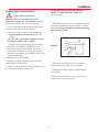
Troubleshooting
IF YOU DO NOT HAVE A SIGNAL:
6. To check voltage at connections, see Figure 9
on page 10. FOLLOW THE NUMERICAL SEQUENCE ON THE DRAWING AND CHECK
VOLTAGE AT:
#1. LNBF voltage. Disconnect the coax cable from
the LNBF. Check voltage from the middle wire to
the shield. There should be +12 to +19 VDC. If no
voltage is present, make sure receiver is on and
check again for +12 to +19 VDC at ends of gray
coax cable.
#2. ëMini-cableí connection voltage at Control Box.
#3. Coax cable at Control Box going to DVB box.
#4. Coax cable at DVB box going to Heyco connector.
1. The signal may be blocked by trees, hills or structures. Pull into an area where no trees or buildings are
in the line of sight from unit to the satellites.
2. Check your +12 VDC power switch. Make sure
it is in the ON position.
3. Check your connections. The receiver must be
connected to the power and coax connected from receiver to the satellite dish. Check demultiplexer
connection.
4. Check your power supply. The +12 VDC power
supply must be hooked up. Check for +12 VDC on the
roof at the connector.
7. Are the dip switches in the correct position
(101, 119 or 092)?
5. Is the rear adjustable base bracket facing the rear
of the vehicle? See Figure 1, page 4.
8. If the unit still does not have a signal, power off and
power back on.
6. Loss of signal may also be caused by snow on roof
of vehicle.
NOTE: The power rocker switch must be ON for the
next steps. Voltage must be +12 VDC, except at the
LNBF, see #2, Figure 9, page 10.
PROBLEM
SOLUTION
Signal strength screen meter shows some
signal strength, but constantly moves up and
down, and is never locked on satellite.
Unit continues to move, but never finds any signal.
Check your power voltage. You may have unfiltered power. You must have a minimum of 12 VDC
to power the LNBF. If the LNBF shows no signal
strength, the unit will move and operate, but you will
not be able to lock onto a signal.
The unit continues to move and the signal strength
screen shows that it is finding the satellites, but will
never lock onto any satellite. Continues to search.
Be sure the switches are set on the correct numbers ó
see page 5, step 5.
The unit moves around in circles, then points off the
front of the coach.
The GPS is not acquiring a signal.
The unit moves in circles and does not find the satellite, then begins to make grinding noise.
Power unit off, then on.
Check switches to make sure they are set correctly.
5
Parts Included • Tools Needed • How to Unpack
About this manual —
We hope this manual will provide clear instructions to install and operate MV-0099.
Two symbols have been used ó
!
Indicates suggestions to make
processes easier for you.
Indicates caution should be taken!
PARTS INCLUDED:
1 Radome
1 Power switch
2 Wall plates (white & brown)
1 Surface mount bracket
1 Cable entry plate
1 large yellow spade connector
2 small red spade connectors
All required screws and washers
1 base with electronics, dish, single LNBF
TOOLS NEEDED FOR UNPACKING & INSTALLATION:
Level
Drill w/3/4î bit
1-1/4î hole saw (if mounting switch in wall)
5/16î Socket for roof screws
1/8î Allen wrench
1/2î Open end wrench
Sealant (consult RV manufacturer for proper type for
your roof material)
LIFT UNIT STRAIGHT UP
UNPACKING THE UNIT
1. Open box and remove packing material.
!
If using knife to open
carton, BE CAREFUL.
Do not cut the dome on
the unit.
2. Lift unit out of box vertically. Do not turn box and
ì rollî out, or turn upside down to remove.
USE 2 PEOPLE
when removing the unit
from the carton.
6
Installation Diagram
FIGURE 1
SWITCH
BASE FOOT
EL MOTOR
LOCATION
POWER
SUPPLY
REAR FOOT
GPS
FRONT OF VEHICLE
ANTENNA
REAR BASE FOOT
MUST DIRECTLY
FACE REAR OF
VEHICLE
HEYCO
CONNECTORS
BASE FOOT
REFLECTOR
7
AZ MOTOR
DVB
Installation
REAR MOUNTING FOOT MUST FACE
DIRECTLY OFF REAR OF VEHICLE,
Figure 1, page 7.
Installing unit on roof of vehicle —
!
Install in DRY conditions only!
IMPORTANT! Do not install this system
in the rain, or under any wet conditions. Moisture
may affect electronics and void your warranty!
5. Place the unit on the roof in its permanent location
and mark around the base bracket, Figure 2. (Make
sure the rear adjustable base foot is directly facing
the back of the coach.)
1. For best performance and to reduce signal acquisition time, park vehicle on a level surface.
2. Select a level spot on your roof for installation.
ï The unit should be no more than +/-1∞ off
level.
ï Be sure any roof-mounted equipment is not
blocking the satellite ìline of sight.î
ï You will need to decide where the wires will enter
the vehicle. A coax and an 18 gauge power wire
will need to be placed in the vehicle. The power
wire will go to the nearest +12 VDC power source;
the coax will be routed to your satellite receiver. These
wires should be hidden.
3. Remove tie used for shipping.
FIGURE 2
4. Plug holes created by shipping strap with white
rubber plugs in hardware bag.
6. Clean roof area where the base feet will be attached to the roof. Do not erase your marks!
5. After selecting location for unit (see number 2), put
the unit on the centerline of the coach.
7. Put approved sealant in the area under the base
foot location.
8. After all base brackets are secured to roof, put
sealant on top of foot and screws.
8
Installation
GPS installation —
Cable entry installation —
The GPS antenna is pre-wired and has a 1 meter foot
cable running through one of the HeycoÆ connectors.
1. Decide the best location for the cables to enter
the vehicle, and the location of the switch and receiver (see ìInstalling the switch and receiverîon
page 10). Drill a 1/2î hole in the roof, push wires inside. Make proper connections.
You must have filtered +12 VDC power source.
Determine location for GPS antenna. It is recommended you place the GPS antenna 1 meter from
dome.
The recommended location for the GPS antenna is
based on having a level location and a clear view of
the sky for the best satellite signal acquisition.
2. Place cable-entry plate over hole and cables. Screw
in place. Seal plate and screw holes with approved
sealant (not included).
IMPORTANT! The GPS must be located 1meter
away from obstructions on roof of vehicle and other
obstructions such as trees, tall buildings, etc. You must
have a clear view of the sky for proper operation.
3. Depending on the length of the cable on the roof,
you may need to use cable clamps or wire ties (not
provided) between the unit and your cable-entry plate.
Clamping the cable every 12î-16î should eliminate
any unnecessary
cable movement,
Figure 6.
FIGURE 6
CABLEENTRY
CABLE
INSTALLING THE POWER SWITCH
1. Decide the location of the power on/off switch. The
switch should be close to the +12 VDC power cable
coming from the MV-0099. Be sure the switch is
turned off before you begin! See diagram on next
page.
Wall or panel mount: Drill 1-1/4î hole, pull wires
through wall or panel.
Surface mount: Determine location and direction of
box. Mount box feed wire into one of the box openings.
Select plate cover (brown or white provided) and snap
the rocker switch into the switch plate. Be sure switch
is off!
9
Installation • Wiring
INSTALLING THE POWER SWITCH, cont’d.
CONNECTING THE RECEIVER —
Satellite
1. Connnect the coax cable
Receiver
from the roof to the
ìSatellite Inî connection
on the receiver. (A dual receiver
SAT IN
upgrade kit is available. Contact
Winegard Company for more information.)
2. Connect the ground wire from the vehicle and the
BLACK ground wire from the MV-0099 together,
using large yellow spade connector.
3. Connect the YELLOW spade connector to
the silver spade on the switch.
4. Connect the RED wire from the MV unit to the
small RED spade connector.
5. Connect small RED spade connector to center
spade on switch.
6. Connect the +12 V power wire from the vehicle to
a small RED spade connector.
7. Connect small RED spade connect to isolated
spade on switch.
Initializing —
1. Be sure vehicle is in a location free of all obstructions and with a clear view of the satellite.
2. DO NOT MOVE VEHICLE during the first
initialization. Power up unit, turn on receiver. FOR
THE FIRST TIME ONLY, the unit may take up to
10 minutes to initially find the satellite signal. The
GPS is also initializing at this time. After the GPS
initializes, the unit will begin searching for the
correct satellite.
INSTALLING THE POWER SWITCH DIAGRAM
ON/OFF ROCKER SWITCH
WITH LIGHT
(Shown in OFF position.)
3. If the GPS does not initialize at this time, turn
off the unit. You may need to move the GPS
antenna to a different location on your roof. After
you move the GPS, DO NOT SECURE TO ROOF.
4. TEST YOUR SYSTEM BEFORE SECURING
THE GPS ANTENNA. Make sure the
TV/receiver has found the correct satellite.
STEPS 2 & 3
TWO GROUND WIRES
1 FROM VEHICLE
1 BLACK WIRE FROM
MV-0099
5. After the correct satellite has been found, secure
GPS antenna by removing adhesive backing and
securing to roof.
STEPS 6 &7
+12 V FROM VEHICLE
STEPS 4 & 5
MV-0099 RED
POWER WIRE
10
Base Diagram
FIGURE 6
#3 COAX CABLE AT
CONTROL BOX
#2 CONTROL
BOX TO LNBF
POWER SUPPLY
(POWER WIRE, SEE DETAIL)
EL MOTOR
GPS ANTENNA
POWER
SUPPLY
BACK OF
VEHICLE
CONTROL
BOX
(DETAIL
BELOW)
DVB
HEYCO CONNECTORS
AZ MOTOR
DVB
#1 LNBF
VOLTAGE
A
CONTROL BOX DETAIL
T
DO NOT USE
11
8-PIN
POWER
TO DVB
AZ MOTOR
TO LNBF
EL MOTOR
Specifications & Warranty
Features and specifications
ï One button operation.
ï 30í power cable and 30í coaxial cable included.
ï GPS satellite signal acquisition.
ï Dome UV protected.
ï Depending on receiver type, you can access
satellites 119∞, 110∞, 101∞ or 92∞.
ï Off-white color compatible with all vehicles.
ï Compact size ó
32î diameter, 15î height
Weight of unit - 43 lbs.
Shipping weight - 59 lbs.
ï No user input required.
ï No data port required for DISH NetworkTM,
DIRECTVÆ or ExpressVu.
ï Operating temperature
-13∞F to +140∞F
ï Tracking greater than 30∞/sec.
ï Elevation range 14.5∞ to 74.5∞;
azimuth unlimited.
TWO YEAR LIMITED WARRANTY
Winegard Company warrants this Winegard product (excluding receiver) against any defects in materials or
workmanship within two (2) years from date of purchase. No warranty claim will be honored unless at the time the claim
is made, you present proof of purchase to an authorized Winegard dealer (if unknown, please contact Winegard
Company, 3000 Kirkwood Street, Burlington, Iowa 52601-2000, telephone 319-754-0600).
Winegard Company (at its option) will either repair or replace the defective product at no charge to you. This warranty
covers parts, but does not cover any costs incurred in removal, shipping or reinstallation of the product. This limited
warranty does not apply if the product is damaged, deteriorates, malfunctions or fails from: misuse, improper
installation, abuse, neglect, accident, tampering, modification of the product as originally manufactured by Winegard,
usage not in accordance with product instructions or acts of nature such as damage caused by wind, lightning, ice or
corrosive environments such as salt spray and acid rain.
The Two Year Warranty is provided on the condition that the equipment is properly delivered with all handling and
freight charges prepaid to your Winegard dealer for repair or return to our factory at the above address. Winegard
dealers will arrange for the replacement or repair and return to you, without charge, the product which failed due to
defective material or workmanship.
WINEGARD COMPANY WILL NOT ASSUME ANY LIABILITIES FOR ANY OTHER WARRANTIES, EXPRESS OR
IMPLIED, MADE BY ANY OTHER PERSON.
ALL OTHER WARRANTIES WHETHER EXPRESS, IMPLIED OR STATUTORY INCLUDING WARRANTIES OF
FITNESS FOR A PARTICULAR PURPOSE AND MERCHANTABILITY ARE LIMITED TO THE TWO YEAR PERIOD
OF THIS WRITTEN WARRANTY.
The foregoing shall be the sole and exclusive remedy of any person whether in contract, tort or otherwise, and
Winegard shall not be liable for incidental or consequential damage or commercial loss, or from any other loss or
damage except as set forth above.
Some states do not allow limitations on how long an implied warranty lasts, or the exclusion of limitation of incidental
or consequential damages, so the above limitations or exclusions may not apply to you.
This warranty gives you specific legal rights and you may also have other rights which vary from state to state.
Winegard Company ï 3000 Kirkwood Street ï Burlington, IA 52601 ï 319/754-0600 Fax 319/754-0787 ï www.winegard.com
Printed in U.S.A. © 2002 Winegard Company 2451007 Rev. 2/10/04
12