1
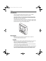
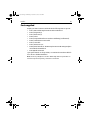
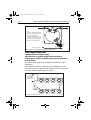
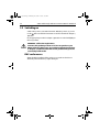
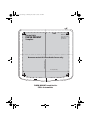
81266_1.book Page 1 Monday, December 5, 2005 9:28 AM
ST60+ Rudder
Angle Indicator
Instrument
Owner’s Handbook
Document reference: 81266-1
Date: December 2005
81266_1.book Page 2 Monday, December 5, 2005 9:28 AM
Raymarine, ST60+ and SeaTalk are trademarks of Raymarine UK Limited
© Handbook contents copyright Raymarine UK Limited 2005
81266_1.book Page i Monday, December 5, 2005 9:28 AM
i
Preface
ContentsContents
Important information
Safety notices
WARNING: Product installation & operation
This equipment must be installed and operated in accordance
with the Raymarine instructions provided. Failure to do so could
result in personal injury, damage to your boat and/or poor
product performance.
WARNING: Electrical safety
Make sure you have switched off the power supply before you
start installing this product.
WARNING: Navigational safety
Although we have designed this product to be accurate and
reliable, many factors can affect its performance. Therefore, it
should serve only as an aid to navigation and should never
replace commonsense and navigational judgement. Always
maintain a permanent watch so you can respond to situations as
they develop.
EMC conformance
All Raymarine equipment and accessories are designed to the best industry
standards for use in the recreational marine environment.
The design and manufacture of Raymarine equipment and accessories conform to
the appropriate Electromagnetic Compatibility (EMC) standards, but correct
installation is required to ensure that performance is not compromised.
Handbook information
To the best of our knowledge, the information in this handbook was correct when
it went to press. However, Raymarine cannot accept liability for any inaccuracies
or omissions it may contain.
In addition, our policy of continuous product improvement may change
specifications without notice. Therefore, Raymarine cannot accept liability for any
differences between the product and the handbook.
81266_1.book Page ii Monday, December 5, 2005 9:28 AM
ii
ST60+ Rudder Angle Indicator Instrument Owner’s Handbook
Product disposal
Waste Electrical and Electronic (WEEE) Directive
The WEEE Directive requires the recycling of waste electrical and
electronic equipment.
Whilst the WEEE Directive does not apply to some of Raymarine's products, we
support its policy and ask you to be aware of how to dispose of this product.
The crossed out wheelie bin symbol, illustrated above, and found on our products
signifies that this product should not be disposed of in general waste or landfill.
Please contact your local dealer, national distributor or Raymarine Technical
Services for information on product disposal.
81266_1.book Page iii Monday, December 5, 2005 9:28 AM
Preface
iii
Contents
Preface
Important information ............................................................................................ i
Safety notices .................................................................................................... i
WARNING: Product installation & operation.......................................... i
WARNING: Electrical safety .......................................................................... i
WARNING: Navigational safety................................................................... i
EMC conformance ............................................................................................. i
Handbook information ...................................................................................... i
Product disposal ............................................................................................... ii
Contents........................................................................................................... iii
Introduction ........................................................................................................... v
Data inputs ............................................................................................................. v
SeaTalk ............................................................................................................. v
Using with SeaTalk Autopilot...................................................................vi
Stand alone operation ..................................................................................... vi
Options ................................................................................................................. vi
Linear transducer............................................................................................. vi
Mounting......................................................................................................... vi
Parts supplied ........................................................................................................vii
Chapter 1: Operation ..................................................................................................... 1
1.1 Getting started ................................................................................................. 1
WARNING: Calibration requirement......................................................... 1
Switching on and off......................................................................................... 1
Displayed information ...................................................................................... 1
Operation with other instruments..................................................................... 1
1.2 Normal use ...................................................................................................... 2
Display illumination.......................................................................................... 2
1.3 Remote control ................................................................................................ 3
Chapter 2: Maintenance & Troubleshooting .......................................................... 5
2.1 Maintenance .................................................................................................... 5
Servicing and safety.......................................................................................... 5
Instrument........................................................................................................ 5
Transducer ........................................................................................................ 5
Cabling ............................................................................................................. 6
2.2 Troubleshooting ............................................................................................... 6
Preliminary procedures..................................................................................... 6
2.3 Fault location ................................................................................................... 6
Technical support.............................................................................................. 7
World wide web....................................................................................... 7
Telephone help line.................................................................................. 7
Help us to help you .................................................................................. 7
81266_1.book Page iv Monday, December 5, 2005 9:28 AM
iv
ST60+ Rudder Angle Indicator Instrument Owner’s Handbook
Chapter 3: Installation ..................................................................................................9
3.1 Planning your installation .................................................................................9
Site requirements..............................................................................................9
Transducer ............................................................................................... 9
Instrument................................................................................................ 9
CAUTION: Keep the rear of the instrument dry....................................9
EMC installation guidelines.............................................................................10
Suppression ferrites................................................................................ 11
Connections to other equipment............................................................ 11
3.2 Procedures .....................................................................................................11
CAUTION: Maintain structural safety .....................................................12
Unpacking.......................................................................................................12
Fitting the instrument......................................................................................12
Surface mounting................................................................................... 12
Flush mounting ...................................................................................... 13
CAUTION: Use the correct screws.............................................................14
Bracket mounting................................................................................... 16
Fitting transducers ..........................................................................................16
Rotary Rudder Reference Transducer ..................................................... 16
CAUTION: Orient the transducer arm correctly ..................................17
Linear Rudder Reference Transducer ...................................................... 19
Transducer cabling ................................................................................. 20
Connecting the instrument .............................................................................21
Introduction ........................................................................................... 21
Signal connections ................................................................................. 21
Power supply connections...................................................................... 22
CAUTION: Protect the power supply.......................................................22
3.3 Switching on ..................................................................................................23
WARNING: Calibration requirement .......................................................23
EMC conformance...........................................................................................23
Chapter 4: Calibration .................................................................................................25
4.1 Introduction ...................................................................................................25
4.2 Rudder angle offset adjustment .....................................................................25
Glossary ...........................................................................................................................27
Index..................................................................................................................................29
81266_1.book Page v Monday, December 5, 2005 9:28 AM
Preface
v
Introduction
Preface
Thank you for purchasing a Raymarine product. We are sure your ST60+
instrument will give you many years of trouble-free operation.
This handbook describes how to install and use the Raymarine ST60+ Rudder
Angle Indicator instrument. This instrument gives a continuously updated (real
time) display of your vessel’s rudder angle.
The ST60+ Rudder Angle Indicator instrument is constructed in a rugged weather
proofed case. It provides a sensitive and stable analog display, to deliver accurate
information under even the most demanding conditions.
ST
6
0+
RU
DD
ER
DIS
P
LO
C
K
03-1
D82
Data inputs
The instrument can be used either as a stand-alone unit, or as part of an
integrated SeaTalk instrumentation system.
SeaTalk
When connected to SeaTalk, the ST60+ Rudder Angle Indicator can operate as a
repeater to any Raymarine SeaTalk autopilot, or provide rudder position
information to another rudder angle instrument.
SeaTalk enables a number of compatible instruments to be interconnected and
operate as a single, integrated navigational system.
Power and data in a SeaTalk system are fed via a single cable, so that instruments
be connected by plugging them into the network. SeaTalk is flexible enough to
adapt to any number of compatible instruments without requiring a central
81266_1.book Page vi Monday, December 5, 2005 9:28 AM
vi
ST60+ Rudder Angle Indicator Instrument Owner’s Handbook
processor. SeaTalk can also communicate with non-SeaTalk equipment, using the
internationally-accepted National Marine Electronics Association (NMEA)
protocol.
In a SeaTalk system, each instrument can be either a master or dedicated repeater
unit. A master instrument is directly connected to a transducer (the device that
provides the raw data), and provides data and control appropriate to its function,
to all other equipment on the SeaTalk network. A repeater instrument is not
directly connected to a transducer but displays information provided by other
equipment in the SeaTalk network.
Using with SeaTalk Autopilot
If the ST60+ Rudder Angle Indicator is part of a system which includes a SeaTalk
autopilot, the rudder reference transducer is connected to the autopilot and the
Rudder Angle Indicator operates in repeater mode, i.e. as a slave display to the
autopilot, with the autopilot data displayed using the Rudder Angle Indicator
analog pointer.
Stand alone operation
In Stand alone operation, the ST60+ Rudder Angle Indicator is connected only to
a rudder reference transducer and does not display information from, or provide
information to, any other instruments.
Options
Linear transducer
A Linear Rudder Reference Transducer option is available for use with ‘bullhorn’
type outboard installations.
Mounting
A standard ST60+ instrument is surface-mounted at the required location. If you
do not want to surface mount your ST60+ instrument, options are available for:
• Flush mounting. If you have ordered the flush mounting option a low-profile
bezel and four fixing screws are also provided.
• Bracket mounting.
81266_1.book Page vii Monday, December 5, 2005 9:28 AM
Preface
vii
Parts supplied
Unpack your ST60+ instrument and check that the following items are present:
• Item 1, ST60+ Rudder Angle instrument with standard bezel.
• Item 2, Fixing studs (2).
• Item 3, Thumb nuts (2).
• Item 4, Gasket.
• Item 5, Rotary Rudder Reference transducer with fittings (not illustrated).
• Item 6, SeaTalk interconnection cable.
• Item 7, Power cable.
• Item 8, Instrument Cover.
• Item 9, Owner’s Handbook. The Warranty document andmounting templates
are included in this Handbook.
• Item 10, Quick Start Guide.
Spare spade terminals are also provided, to re-terminate the transducer cable if it
has to be cut to facilitate installation.
Note: The above packing list is for an ST60+ Rudder Angle Indicator system. Where an
instrument is purchased separately, a transducer is not included.
81266_1.book Page viii Monday, December 5, 2005 9:28 AM
viii
ST60+ Rudder Angle Indicator Instrument Owner’s Handbook
2
3
2
3
SET
DISP
4
1
6
5
7
ST60+
Rudder
Angle
Instrument
Owner's
Handbook
ST60+ Rudder
Angle Indicator
Instrument
ST60+
DISP
RUDDER
SET
8
9
10
D8204-1
Quick Start Guide
81266_1.book Page 1 Monday, December 5, 2005 9:28 AM
1
Chapter 1: Operation
1.1 Getting started
This handbook describes how to operate, maintain and install the Raymarine
ST60+ Rudder Angle Indicator Instrument. The instrument provides a real-time
indication of rudder position as determined by the associated Rudder Reference
Transducer.
WARNING: Calibration requirement
To ensure this product performs at its best on your boat, you
MUST calibrate it before use, in accordance with the instructions
in Chapter 4, Calibration. Do NOT use the product until you have
successfully calibrated it.
Switching on and off
All the time that power is applied to the instrument, you can use the button to
switch the instrument off and on as follows:
• To switch the instrument off, hold down the button for approximately
5 seconds. After this time, a switch off count down of 4 seconds occurs. Keep
the button pressed during this period, to switch off the instrument.
• To switch the instrument back on, hold down the button for approximately
1 second.
When the power supply is switched off, none of the instrument buttons (including
) has any effect.
Notes: (1) Each time power to the instrument is switched on, the instrument is ini-
tially in the on condition. You do not need to use the button to switch
the instrument on.
(2) When the instrument is on, the operation of the
button will perform
other operating functions, as described below.
Displayed information
The ST60+ Rudder Angle Indicator pointer shows the rudder position in real-time.
The instrument scale range gives an expanded indication from -40° to +40°
about zero.
Operation with other instruments
When the ST60+ Rudder Angle Indicator is connected to an operational autopilot
via SeaTalk, the instrument acts as slave to the autopilot, which receives data
81266_1.book Page 2 Monday, December 5, 2005 9:28 AM
2
ST60+ Rudder Angle Indicator Instrument Owner’s Handbook
from the Rudder Angle Indicator Transducer and passes the information via the
SeaTalk bus.
1.2 Normal use
As the ST60+ Rudder Angle Indicator operates in real time, very little operator
action is necessary during normal use except to observe the instrument as
required to ascertain the rudder angle.
Note: If rudder angle information is not available on the SeaTalk bus, the analog pointer
oscillates ±10° about the top of the dial.
The
button is the only button used during normal operation (see button
functions illustration). The set, < and > buttons are reserved for calibration
mode, see Chapter 4, Calibration. All button presses called for in this handbook
are momentary, unless otherwise stated.
Used for calibration
(see Chapter 4, Calibration )
Button functions
D8205-1
Press for 1 second
to adjust illumination level
Display illumination
When the instrument is first powered up, the display illumination is set to its
lowest (courtesy) level, to facilitate initial access to the buttons.
To adjust the level of display illumination:
1. Hold down the button for approximately 1 second, to enter the illumination-adjust mode.
2. There are four preset illumination levels from a courtesy level to full brightness. Momentarily press the button to cycle through these levels until you
81266_1.book Page 3 Monday, December 5, 2005 9:28 AM
Chapter 1: Operation
3
reach the level you want. The selected level is transmitted to all other instruments on the SeaTalk bus.
3. Press any other button to leave the illumination-adjust mode.
Note: The display will return to normal operation 7 seconds after the last button press.
1.3 Remote control
The ST60+ Rudder Angle Indicator does not support the SeaTalk remote control
facility. You can control the instrument only with the front panel buttons.
81266_1.book Page 4 Monday, December 5, 2005 9:28 AM
4
ST60+ Rudder Angle Indicator Instrument Owner’s Handbook
81266_1.book Page 5 Monday, December 5, 2005 9:28 AM
5
Chapter 2: Maintenance &
Troubleshooting
2.1 Maintenance
Servicing and safety
• Raymarine equipment should be serviced only by authorized Raymarine service technicians. They will ensure that service procedures and replacement
parts used will not affect performance. There are no user serviceable parts in
any Raymarine product.
• Some products generate high voltages, so never handle the cables/connectors when power is being supplied to the equipment.
• When powered up, all electrical equipment produces electromagnetic fields.
These can cause adjacent pieces of electrical equipment to interact with one
another, with a consequent adverse effect on operation. In order to minimize
these effects and enable you to get the best possible performance from your
Raymarine equipment, guidelines are given in the installation instructions, to
enable you to ensure minimum interaction between different items of equipment, i.e. ensure optimum Electromagnetic Compatibility (EMC).
• Always report any EMC-related problem to your nearest Raymarine dealer.
We use such information to improve our quality standards.
• In some installations, it may not be possible to prevent the equipment from
being affected by external influences. In general this will not damage the
equipment but it can lead to spurious resetting action, or momentarily may
result in faulty operation.
Instrument
Certain atmospheric conditions may cause condensation to form on inside of the
instrument window. This will not harm the instrument and can be cleared by
increasing the instrument illumination to the brightest setting.
Periodically clean your ST60+ instrument with a soft damp cloth. Do NOT use
chemical and/or abrasive materials to clean the instrument.
Transducer
Refer to the Installation and Maintenance instructions supplied with the
transducer.
81266_1.book Page 6 Monday, December 5, 2005 9:28 AM
6
ST60+ Rudder Angle Indicator Instrument Owner’s Handbook
Cabling
Examine all cables for chafing or other damage to the outer shield, and where
necessary, replace and re-secure.
2.2 Troubleshooting
Preliminary procedures
Changes in the electronic environment may adversely affect the operation of your
ST60+ equipment. Typical examples of such changes are:
• Electrical equipment has recently been installed or moved aboard your vessel.
• You are in the vicinity of another vessel or shore station emitting radio signals.
If you appear to have a problem, first ensure that the EMC requirements (see
Chapter 3, Installation ) are still being met before further investigating the
problem.
2.3 Fault location
All Raymarine products are subjected to comprehensive test and quality
assurance programmes prior to packing and shipping. If a fault occurs, the
following table may help to identify and rectify the problem.
Fault
Cause
Remedy
No rudder angle information.
No power supply.
Check power supply.
Check SeaTalk cabling and
connector security.
Check fuse/circuit breaker.
No transfer of information
SeaTalk cabling fault.
between instruments or a group
of instruments (e.g. illumination
levels).
Check security of SeaTalk
connectors.
Check condition of SeaTalk
cables.
Isolate faulty instrument by
disconnecting instruments
one by one.
81266_1.book Page 7 Monday, December 5, 2005 9:28 AM
Chapter 2: Maintenance & Troubleshooting
7
Technical support
Raymarine provides a comprehensive customer support service, on the world
wide web and by telephone help line. Please use either of these facilities if you are
unable to rectify a problem.
World wide web
Please visit the Customer Support area of our web site at:
www.raymarine.com
As well as providing a comprehensive Frequently Asked Questions section and
servicing information, the web site gives e-mail access to the Raymarine Technical
Support Department and a details of the locations of Raymarine agents,
worldwide.
Telephone help line
If you do not have access to the world wide web, please call our help line.
In the USA, call:
• +1 800 539 5539, extension 2444 or
• +1 603 881 5200 extension 2444
In the UK, Europe the Middle East or the Far East, call:
• +44 (0) 23 9271 4713 (voice)
• +44 (0) 23 9266 1228 (fax)
Help us to help you
When requesting service, please quote the following product information:
• Equipment type.
• Model number.
• Serial number.
• Software issue number.
The Software issue number can be ascertained by means of the Intermediate
Calibration facility, see Chapter 4, Calibration.
81266_1.book Page 8 Monday, December 5, 2005 9:28 AM
8
ST60+ Rudder Angle Indicator Instrument Owner’s Handbook
81266_1.book Page 9 Monday, December 5, 2005 9:28 AM
9
Chapter 3: Installation
This chapter describes how to install the ST60+ Rudder Angle Indicator
instrument and associated transducer.
Rotary and linear Raymarine Rudder Angle Transducers are available for use with
the ST60+ Rudder Angle Indicator instrument.
If the instrument is being installed as stand-alone, the transducer cable is
connected to the rear of the instrument. If being installed as part of a system
incorporating a SeaTalk Autopilot, the transducer is connected to the Autopilot.
For advice, or further information regarding the installation of this equipment,
please contact the Raymarine Product Support Department or your own National
Distributor.
3.1 Planning your installation
Before starting the installation, spend some time considering the best positions
for the instrument, such that the Site requirements and the EMC installation
guidelines are satisfied.
Site requirements
Transducer
The siting of the Rudder Reference Transducer depends on the type of vessel.
Fitting details and dimensions are given in the Fitting transducers section of this
chapter.
Instrument
CAUTION: Keep the rear of the instrument dry
Keep the rear of instrument dry. Failure to observe this caution
could result in damage if water enters the instrument through
the breathing hole or comes into contact with the electrical
connectors.
ST60+ instruments can be fitted either above or below deck, provided that the
rear of the instrument is sited where it is protected from contact with water.
Each instrument must also be positioned where it is:
• Easily read by the helmsman.
• Protected against physical damage.
• At least 9 in (230 mm) from a compass.
81266_1.book Page 10 Monday, December 5, 2005 9:28 AM
ST60+ Rudder Angle Indicator Instrument Owner’s Handbook
4.33 in (110 mm)
0.93 in
(23.5 mm)
0.6 in
(15 mm)
With low profile bezel
(flush mount)
4.90 in (124 mm)
ST60+ instrument dimensions
490 in (124 mm)
With standard bezel
(surface mount)
4.53 in (115 mm)
3.54 in (90 mm)
diameter
• At least 20 in (500 mm) from radio receiving equipment.
• Reasonably accessible from the rear for installation and servicing.
3.54 in (90 mm)
diameter
10
0.25 in
1.4 in
(6.50 mm) (35 mm)
D8146-1
EMC installation guidelines
All Raymarine equipment and accessories are designed to the best industry
standards for use in the recreational marine environment.
Their design and manufacture conforms to the appropriate Electromagnetic
Compatibility (EMC) standards, but correct installation is required to ensure that
performance is not compromised. Although every effort has been taken to ensure
that they will perform under all conditions, it is important to understand what
factors could affect the operation of the product.
The guidelines given here describe the conditions for optimum EMC performance,
but it is recognized that it may not be possible to meet all of these conditions in all
situations. To ensure the best possible conditions for EMC performance within the
constraints imposed by any location, always ensure the maximum separation
possible between different items of electrical equipment.
For optimum EMC performance, it is recommended that wherever possible:
• Raymarine equipment and cables connected to it are:
81266_1.book Page 11 Monday, December 5, 2005 9:28 AM
Chapter 3: Installation
11
• At least 3 ft (1 m) from any equipment transmitting or cables carrying
radio signals e.g. VHF radios, cables and antennas. In the case of SSB
radios, the distance should be increased to 7 ft (2 m).
• More than 7 ft (2 m) from the path of a radar beam. A radar beam can normally be assumed to spread 20 degrees above and below the radiating
element.
• The equipment is supplied from a separate battery from that used for engine
start. Voltage drops below 10 V in the power supply to our products, and
starter motor transients, can cause the equipment to reset. This will not damage the equipment, but may cause the loss of some information and may
change the operating mode.
• Raymarine specified cables are used. Cutting and rejoining these cables can
compromise EMC performance and must be avoided unless doing so is
detailed in the installation manual.
• If a suppression ferrite is attached to a cable, this ferrite should not be
removed. If the ferrite needs to be removed during installation it must be reassembled in the same position.
Suppression ferrites
The following illustration shows typical cable suppression ferrites used with
Raymarine equipment. Always use the ferrites supplied by Raymarine.
D3548-6
Connections to other equipment
If your Raymarine equipment is to be connected to other equipment using a cable
not supplied by Raymarine, a suppression ferrite MUST always be attached to the
cable near the Raymarine unit.
3.2 Procedures
As it is not practical to describe procedures for all possible installation scenarios,
the procedures given here describe the broad requirements for installing an
ST60+ Rudder Angle Indicator instrument and its associated transducer. Adapt
these procedures as appropriate, to suit your individual requirement.
81266_1.book Page 12 Monday, December 5, 2005 9:28 AM
12
ST60+ Rudder Angle Indicator Instrument Owner’s Handbook
CAUTION: Maintain structural safety
Where it is necessary to cut holes (e.g. for cable routing and
instrument mounting), ensure that these will not cause a hazard
by weakening critical parts of the vessel’s structure.
Unpacking
Unpack your ST60+ instrument and check that the items detailed in the
Introduction to this handbook are present.
Each ST60+ instrument is supplied with a standard bezel for surface mounting.
Optional mounting kits are available for flush mounting and bracket mounting
the instrument. If you have ordered the flush mounting option, a low-profile bezel
and four fixing screws are also provided.
Fitting the instrument
The ST60+ Rudder Angle Indicator instrument can be installed using one of a
number of different mounting options:
• Surface Mounting. Gives a profile of approximately 0.95 in (24 mm).
• Flush Mounting. Gives a profile of approximately 0.25 in (6 mm)
• Bracket Mounting.
The ST60+ Rudder Angle Indicator instrument can also be mounted behind a
panel with just the instrument dial and buttons visible.
Surface mounting
To surface mount your ST60+ instrument (see the Surface mounting illustration):
1. Ensure that:
• The selected location is clean, smooth and flat.
• There is sufficient space behind the location to accommodate the rear of
the instrument and connectors.
2. Apply the surface mount template (supplied at the rear of this handbook) to
the selected location and mark the centers for the fixing studs (1) and the
aperture (3) that will take the rear casing of the instrument.
3. Drill out the two 0.2 in (5 mm) fixing stud clearance holes (2).
4. Cut out the clearance hole (3) then remove the template.
5. Peel off the protective sheet from the self-adhesive gasket (4) then stick the
gasket into position on the rear of the instrument.
6. Screw the two fixing studs into the threaded sockets on the rear of the instrument.
81266_1.book Page 13 Monday, December 5, 2005 9:28 AM
Chapter 3: Installation
13
Surface mounting
4
1 2
1
3
5
2
5
D8147-1
7. Mount the assembled instrument, studs, bezel and gasket into the panel.
Secure from behind with the thumb nuts (5).
Flush mounting
The Flush Mounting Kit uses a low-profile bezel to reduce the fitted profile of the
instrument to approximately 0.25 in (6 mm) above the panel fascia.
Fitting the flush mount bezel
In order to flush-mount your ST60+ instrument, you must first replace the
standard bezel with the flush mount bezel as follows:
1. Hold the instrument in both hands with the display towards you.
2. Using both thumbs, gently press an upper corner of the instrument from the
bezel, then remove the bezel from the instrument. Retain the rubber keypad
which is released when the bezel is removed.
81266_1.book Page 14 Monday, December 5, 2005 9:28 AM
ST60+ Rudder Angle Indicator Instrument Owner’s Handbook
D8148-1
14
3. Referring to the Fitting the flush mount bezel illustration, insert the panel
seal (8) in the corresponding recess on the back of the flush mount bezel (7).
4. Place the instrument (11) face upwards on a flat surface, then place the rubber keypad (10) in position around the display window (i.e. so that each button outline is located over its associated button on the instrument).
Fitting the flush mount bezel
8
9
10
11
12
D8149-1
7
81266_1.book Page 15 Monday, December 5, 2005 9:28 AM
Chapter 3: Installation
15
5. Place the keypad seal (9) in position on the keypad (i.e. so that the holes in the
seal accept the appropriate keypad buttons).
6. Place the assembled flush mount bezel and panel seal, in position on the
instrument, so that the rubber keys are correctly located in the holes on the
bezel, then clip the bezel and instrument together.
CAUTION: Use the correct screws
It is essential that only screws of the correct size are used to
secure the instrument to the bezel. Failure to observe this caution
could result in damage to both the instrument and the bezel.
7. Using the four, self-tapping screws (12) provided, secure the instrument and
bezel together. Fit the screws from the rear of the instrument and tighten
them sufficiently to secure the instrument and bezel together. DO NOT OVERTIGHTEN.
Flush mounting
1
4
3
1
5
6
5
D8150-1
Flush mounting procedure
Flush mount your instrument (see the Flush mounting illustration) as follows:
1. Assemble the ST60+ instrument and flush mount bezel as described under
Fitting the flush mount bezel.
81266_1.book Page 16 Monday, December 5, 2005 9:28 AM
16
ST60+ Rudder Angle Indicator Instrument Owner’s Handbook
2. Ensure that:
• The panel on which you intend to mount the instrument is between
0.12 in (3 mm) and 0.78 in (20 mm) thickness.
• The selected location is clean, smooth and flat.
• There is sufficient space behind the location to accommodate the rear of
the instrument and connectors.
3. Apply the flush mount template (supplied at the rear of this handbook) to the
selected location and mark out the aperture into which the assembled instrument and bezel will sit.
4. Cut out the aperture (3) for the assembled instrument and bezel and remove
the template.
5. Peel off the protective sheet from the self-adhesive gasket (4) then stick the
gasket into position on the rear of the bezel.
6. Screw the two fixing studs (1) into the threaded sockets on the rear of the
instrument.
7. Mount the assembled instrument, studs, bezel and gasket into the panel.
8. Locate the flush mount bracket (6) onto the fixing studs and secure the assembly to the panel with the thumb-nuts (5).
Bracket mounting
A Control Unit Mounting Bracket (Part No. E25009) enables you to mount your
ST60+ instrument in locations where other forms of mounting are impractical.
Although bracket mounting provides a useful alternative method for securing
your instrument, it is only suitable for use in positions where the instrument will
not be exposed to water.
To bracket mount your ST60+ instrument, do so in accordance with the Control
Unit Mounting Bracket Instruction Sheet.
Fitting transducers
The Rudder Reference Transducer duplicates movement of the tiller arm to
provide the instrument or the autopilot as appropriate, with the exact position of
the vessel’s rudder.
Rotary and Linear Rudder Reference Transducers are available. The Rotary type is
suitable for most installations, but the Linear type is designed for use with
‘bullhorn’ type outboard installations. Refer to the fitting instructions for either
the Rotary Rudder Reference Transducer or the Linear Rudder Reference
Transducer, as appropriate.
81266_1.book Page 17 Monday, December 5, 2005 9:28 AM
Chapter 3: Installation
17
If you are fitting an ST60+ Rudder Angle Indicator instrument as part of a system
which includes a SeaTalk autopilot, the transducer must be connected directly to
the autopilot. The ST60+ Rudder Angle Indicator will then act as a slave to the
autopilot.
Rotary Rudder Reference Transducer
152mm (6in)
61mm (2.4in)
139.7mm (5.5in)
69.5mm (2.7in)
Rotary Rudder Reference Transducer - dimensions
D4426-1
Mounting
1. Ensure that the base height of the Rotary Rudder Reference Transducer is such
that it is able to maintain the correct vertical alignment between the transducer and tiller arm (as shown).
Tiller arm
Transducer
Mounting base
Vertical alignment of transducer and tiller arm
D4427-1
2. Using Rotary Rudder Reference Transducer template (supplied at the rear of
this handbook), mark the centers for the three securing screws at a suitable
location adjacent to the rudder stock.
3. Drill out the three 3 mm holes then, using the three self-tapping screws provided, secure the Rotary Rudder Transducer in position.
Note: To ensure precise rudder position indication, the Rotary Rudder Reference Transducer incorporates a spring to remove any mechanical backlash in the tiller linkage.
81266_1.book Page 18 Monday, December 5, 2005 9:28 AM
18
ST60+ Rudder Angle Indicator Instrument Owner’s Handbook
Connecting to the tiller
CAUTION: Orient the transducer arm correctly
As the Rotary Rudder Reference Transducer arm movement is
limited to ±60°, ensure that you install the transducer so the arm
is opposite the point of cable entry when the rudder is
amidships. Failure to do this could result in damage if the arm is
driven onto its end stops by the steering system.
When connecting the Rotary Rudder Reference Transducer to the tiller, ensure this
is done in accordance with the limits shown in the Rotary Rudder Reference
Transducer - as fitted illustration (below), and that the tiller and arm of the Rotary
Rudder Reference Transducer are parallel to each other.
1. With the rudder amidships, ensure that the Rotary Rudder Reference Transducer arm is opposite the point of cable entry and at 90° to the connecting
bar. If any minor adjustment is necessary, loosen the three securing screws,
rotate the Rotary Rudder Reference Transducer body to achieve the required
adjustment, then re-tighten the screws.
± 60
maximum
travel
permitted
Cable
entry
Parallel
40
max
90
Min
75mm
(3in)
Max
310mm
(12.2in)
A
Rudder amidships
40 max
Min 101mm (4in)
'A' 140mm (5.5in)
Max 190mm (7.5in)
Rotary Rudder Reference Transducer - as fitted
D4428-1
2. Position the tiller pin within the limits shown. Ideally, dimension ‘A’ should be
5.5 in (140 mm). Secure the tiller ball-pin to the tiller arm using the two selftapping screws provided.
81266_1.book Page 19 Monday, December 5, 2005 9:28 AM
Chapter 3: Installation
19
Note: Variation within the given limits will not degrade autopilot performance but will
slightly alter the scaling of the ST60+ Rudder Angle Indicator display.
3. Cut the threaded rod to length and screw one lock-nut and ball socket onto
each end of the rod.
4. Offer up the rod (with ball sockets) to the Rotary Rudder Reference Arm and
tiller, making adjustments to the ball sockets as required then, supporting the
ball sockets (by means of a suitable wrench) tighten the locking nuts.
5. Press each socket onto its corresponding ball-pin.
6. Move the rudder from side to side and ensure that the linkage is free from any
obstruction at all rudder angles.
Note: If the Rotary Rudder Reference Transducer has to be mounted in an inverted position, the connections for the red and green wires at the ST60+ Rudder Angle Indicator instrument (or course computer) must be reversed.
Linear Rudder Reference Transducer
The Linear Rudder Reference Transducer is designed for use with ‘bullhorn’ type
outboard installations.
2
7 8 3
9
10
11
6
5
4
Fitting the Linear Rudder Reference Transducer
12
1
D4429-1
Mounting
1. Operate the steering system so that the ‘bullhorn’ ram (1) is positioned amidships.
2. Release the hydraulic pressure from the vessel’s hydraulic steering system (if
required). Refer to the manufacturer’s instructions for correct procedures.
81266_1.book Page 20 Monday, December 5, 2005 9:28 AM
20
ST60+ Rudder Angle Indicator Instrument Owner’s Handbook
3. Loosen the starboard bolt that secures the ‘bullhorn’ ram (1) shaft to the end
bracket (2).
4. Assemble the U-bracket (3) over the end bracket (2) and the shaft of the ’bullhorn’ ram (1).
5. Hand tighten the starboard ‘bullhorn’ bolt to hold the U-bracket (3) in position.
6. Fully open the hose clamps (6) using a flat-blade screwdriver.
7. Hang the hose clamps (6) over the ‘bullhorn’ ram (1).
8. Site the spacers (4) on the ‘bullhorn’ ram (1) and hold, temporarily, with adhesive tape.
9. Pull the shaft (9) out of the linear feedback transducer (5) until the alignment
mark (10) is level with the end of the body (11).
10. Position the linear feedback transducer (5) on top of the spacers (4) so that the
threaded end of the shaft passes through the U-bracket (3).
Note: The linear feedback transducer should, under normal circumstances, be assembled
with the shaft (9) pointing to starboard. However, if it is not possible to orientate the unit in
this way, port installation is possible provided that the red and green wires are reversed at
the ST60+ Rudder Angle Indicator instrument (or course computer).
11. With the adjustment screw and barrel aligned with the spacers, close the hose
clamps (6) around the linear feedback transducer (5) and the ‘bullhorn’ ram
(1).
12. Tighten the ‘bullhorn’ bolt to retain the U-bracket (3).
13. Fit and tighten the nut (7) and washer (8) to the shaft of the linear feedback
transducer (5).
Transducer cabling
General
Each transducer type is supplied with sufficient cable to run from the mounted
position to either the ST60+ Rudder Angle Indicator instrument (for operation as
a master) or to an autopilot (for operation as a repeater).
If you are connecting for repeater operation, use the instructions in your autopilot
handbook to connect the transducer to the autopilot.
Running the cable
The manner in which you run the cable will depend on the locations of the
transducer and instrument (or autopilot). The following guidelines are provided:
• When running cable from a Linear Rudder Reference Transducer, leave a loop
of cable at the end of the Linear Rudder Reference Transducer, sufficient to
allow for movement of the ‘bullhorn’.
81266_1.book Page 21 Monday, December 5, 2005 9:28 AM
Chapter 3: Installation
21
• If the cable has to be fed through the deck, always use a proprietary deck
gland.
• Where cables are fed through holes, always use grommets to prevent chafing.
• Secure long cable runs so they do not present a hazard.
• Although the transducer cable is fitted with spade connectors for direct
connection to the rear of the instrument, it may be necessary to remove these
to facilitate installation e.g. if you want incorporate a junction box in the cable
run or if the cable has to be routed through narrow apertures. Extra spade
connectors are provided, to replace any that are removed when running the
cable. When fitting spade connectors, prepare the cable as at (a) in the
following illustration, then fold back the wire strands and insert into the
spade connector as at (b). Ensure the wire strands do not extend beyond the
rear of the spade connector insulation, then crimp the connector to the wire.
50 mm
6 mm
(a)
(b)
3 mm
D4467-6
Connecting the instrument
Introduction
The ST60+ Rudder Angle Indicator instrument can be connected:
• To the transducer as a stand-alone instrument.
• To SeaTalk.
Instruments connected to SeaTalk derive their power directly from SeaTalk and no
separate power connection is necessary. Where a SeaTalk system includes an
autopilot, the power for the system is provided by the autopilot.
A range of Raymarine SeaTalk extension cables is available to connect separated
instruments. These cables are supplied with a SeaTalk connector fitted to each
end. A junction box can be used to join cables.
Signal connections
Make the necessary connections to your ST60+ instrument (see the Connections
to ST60+ Rudder Angle Indicator instrument illustration).
81266_1.book Page 22 Monday, December 5, 2005 9:28 AM
22
ST60+ Rudder Angle Indicator Instrument Owner’s Handbook
SeaTalk cable
SeaTalk cable
Note:
If the ST60+ Rudder Angle Indicator
pointer moves in the wrong direction
with respect to the rudder
movement, swap the Red and Green
connections. This may be necessary
if the Rudder Reference Transducer is
fitted in a non-standard manner.
Screen
Green
Blue
Red
D8206-1
Cable from transducer
Connections to ST60+ Rudder Angle Indicator instrument
Power supply connections
CAUTION: Protect the power supply
Ensure that the 12 V power supply for the instrument is
protected by a suitably rated fuse or protective circuit breaker.
SeaTalk systems
Ensure that the power supply for the SeaTalk bus is protected by a 5 A fuse or
circuit breaker.
Systems with a large number of instruments on the SeaTalk bus may require
connections to the power supply from each end of the system (‘ring-main’ style),
to maintain sufficient voltage throughout the system.
Red
5 A fused,
12 V dc supply
(typically provided
by autopilot)
1
2
3
4
Screen
Instruments
5 to 16
Red
Screen
SeaTalk power connections
20
19
18
17
D4311-1
81266_1.book Page 23 Monday, December 5, 2005 9:28 AM
Chapter 3: Installation
23
This requirement depends on the total length of the cable run and the total
number of instruments in the system, as follows:
Cable run
No. of instruments
Power connections
Up to 10 m
13 maximum
26 maximum
1
2
Up to 20 m
7 maximum
13 maximum
1
2
Stand alone instruments
Stand-alone instruments are not connected to SeaTalk and therefore need to be
connected to an alternative 12 V power source. Power cables are available in 2 m
and 9 m lengths.
To fit a power cable:
1. Ensure the intended power source is switched off.
2. Run the power cable from the instrument to a suitable 12 V dc power source.
3 A over-current
circuit breaker
Red
12 V dc
supply
Screen
Power connections for stand-alone instrument
D4310-6
3. If the cable has not already been trimmed at the power supply end:
i. Cut the cable to length and trim back an appropriate amount of the outer
sheath.
ii. Cut back and insulate the yellow wire.
4. Connect the screen to the power supply 0 V terminal.
5. Connect the red wire, via a 3 A fuse or protective circuit breaker, to the power
supply +12 V terminal.
6. Insert the power cable connector into one of the SeaTalk connectors at the
rear of the instrument.
81266_1.book Page 24 Monday, December 5, 2005 9:28 AM
24
ST60+ Rudder Angle Indicator Instrument Owner’s Handbook
3.3 Switching on
Switch on the power to your ST60+ instrument. When the power is on, you can
use the button to switch the instrument on and off as described in Chapter 1,
Operation.
Use the appropriate procedure in Chapter 1, Operation to set the backlighting to
the level you want.
WARNING: Calibration requirement
To ensure this product performs at its best on your boat, you
MUST calibrate it before use, in accordance with the instructions
in Chapter 4, Calibration. Do NOT use the product until you have
successfully calibrated it.
EMC conformance
Always check the installation before going to sea to make sure that it is not
affected by radio transmissions, engine starting etc.
81266_1.book Page 25 Monday, December 5, 2005 9:28 AM
25
Chapter 4: Calibration
4.1 Introduction
Before using the Rudder Angle Indicator instrument for navigational purposes, it
must be aligned with the Rudder Reference Transducer to counter any offset and
ensure that the rudder position is accurately monitored.
4.2 Rudder angle offset adjustment
Rudder angle offset adjustment removes any deviation between the reading on
the ST60+ Rudder Angle Indicator display and the Rudder Reference Transducer.
To adjust for any offset, proceed as follows:
1. Center the rudder and check that the display analog pointer is within ±7° of
zero. If the analog pointer reading exceeds the limits ±7°, the Rudder Reference Transducer should be realigned in order to avoid scale inaccuracies (see
Chapter 3, Installation ).
2. With the rudder centered, press and hold the set button for 2 seconds. The
instrument will emit an audible beep to indicate that you are in calibration
mode.
Note: You can enter calibration mode only when the instrument is in master mode. If the
instrument is in repeater mode and you attempt to enter calibration mode, the instrument
will beep twice when the set button is released, to indicate an invalid button press.
3. Use the < (decrement) and/or > (increment) buttons to adjust the Rudder
Angle Indicator display pointer to the zero position in 1° steps, or press and
hold either < or > for rapid change.
4. Press the set button for 2 seconds to save the new setting and exit calibration
mode.
Note: If, during calibration, no button is pressed for a period of 60 seconds, calibration
mode is exited without change.
81266_1.book Page 26 Monday, December 5, 2005 9:28 AM
26
ST60+ Rudder Angle Indicator Instrument Owner’s Handbook
81266_1.book Page 27 Monday, December 5, 2005 9:28 AM
27
Glossary
APP
Apparent
AVE
Average
AWA
Apparent Wind Angle (relative to the vessel)
AWS
Apparent Wind Speed
BTW
Bearing To Waypoint
CMG
Course Made Good
COG
Course Over Ground
DMG
Distance Made Good
DTW
Distance To Waypoint
EMC
Electro Magnetic Compatibility
ETA
Estimated Time of Arrival
GPS
Global Positioning System
HDG
Heading
KM
Kilometer(s)
KMH
Kilometers per hour
KTS
Knot(s)
LAT
Latitude
LCD
Liquid Crystal Display
LON
Longitude
LTR
Liter(s)
81266_1.book Page 28 Monday, December 5, 2005 9:28 AM
28
ST60+ Rudder Angle Indicator Instrument Owner’s Handbook
M
Magnetic or meters
MAG
Magnetic
MOB
Man Overboard
MPH
Miles per hour
NM
Nautical mile(s)
Response
The sensitivity of an instrument, to data changes.
RF
Radio Frequency
SeaTalk
Raymarine proprietary communication system which links products, to provide a
single, integrated system sharing power and data.
SM
Statute mile(s)
SOG
Speed Over Ground
SPD
Speed
T
True
TTG
Time To Go
TWA
True Wind Angle relative to the vessel, taking into account the speed of the vessel.
TWD
True Wind Direction.
TWS
True Wind Speed.
VMG
Velocity Made Good.
WP
Waypoint
XTE
Cross Track Error
81266_1.book Page 29 Monday, December 5, 2005 9:28 AM
29
Index
B
L
Backlighting adjustment, 2
Button functions, 2
Linear rudder reference transducer, 19
M
C
Mounting options, vi
Mounting options (instrument), 12
Calibration requirement, 1, 23
Cleaning, 5
Condensation, 5
P
Display setup, 2
Displayed information, 1
Disposing of the product, ii
Parts supplied, vii–viii
Power supply
SeaTalk systems, 22
stand alone instrument, 22
Product disposal, ii
E
R
D
EMC information, i, 5, 10, 23
H
Help lines, 7
I
Installing
instrument, 12
bracket mounting, 16
flush mounting, 13
power supply connections, 22
requirements, 9
signal connections, 21
surface mounting, 12
planning, 9
transducer, 16
linear rudder reference, 19
rotary rudder reference, 16
running cable, 20
Instrument mounting options, 12
Rotary rudder reference transducer, 16
Rudder angle offset, 25
S
Safety
calibration requirement, 1, 23
electrical, i
general, i
navigation, i
SeaTalk overview, v
Servicing & safety, 5
Setting up
backlighting, 2
rudder angle offset, 25
Site requirements
instrument, 9
Switching on/off, 1, 23
T
Technical support, 7
Troubleshooting, 6
81266_1.book Page 30 Monday, December 5, 2005 9:28 AM
30
ST60+ Rudder Angle Indicator Instrument Owner’s Handbook
81266_1.book Page 31 Monday, December 5, 2005 9:28 AM
Remove material
from shaded areas only
Sun cover edge
Instrument edge
1.185 in (30.1 mm)
1.18 in (30.0 mm)
SURFACE MOUNT template for
ST60+ Instruments
D8157-1
Cut hole
3.54 in (90 mm)
diameter
1.77 in (45.0 mm)
Drill hole, 3/16 in (5 mm)
diameter in 2 positions
TOP
1.76 in (44.6 mm)
SURFACE MOUNT
Template
81266_1.book Page 32 Monday, December 5, 2005 9:28 AM
81266_1.book Page 33 Monday, December 5, 2005 9:28 AM
TOP
Control Unit
Drill hole,
1/4 in (6.5 mm)
diameter in
4 positions
FLUSH MOUNT
Template
4.47 in (113.5 mm)
Remove material from shaded area only
4.3 in (109 mm)
Sun cover edge
Instrument edge
FLUSH MOUNT template for
ST60+ Instruments
81266_1.book Page 34 Monday, December 5, 2005 9:28 AM