1
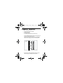
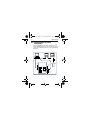
81166_5.book Page -1 Friday, February 2, 2007 11:47 AM
PC/SeaTalk/NMEA
Interface Box
Owner’s Handbook
Document Number: 81166-5
Date: February 2007
81166_5.book Page 0 Friday, February 2, 2007 11:47 AM
Copyright © Raymarine UK Ltd.
81166_5.book Page i Friday, February 2, 2007 11:47 AM
Preface
i
Preface
Important information
Safety notices
WARNING: Product installation &
operation
This equipment must be installed and
operated in accordance with the Raymarine
instructions provided. Failure to do so could result in
personal injury, damage to your boat and/or poor
product performance.
WARNING: Electrical safety
Make sure you have switched off the power
supply before you start installing this
product.
WARNING:
Although we have designed this product to be
accurate and reliable, many factors can affect
its performance. Therefore, it should serve
only as an aid to navigation and should never replace
commonsense and navigational judgement. Always
maintain a permanent watch so you can respond to
situations as they develop.
81166_5.book Page ii Friday, February 2, 2007 11:47 AM
ii
Preface
EMC conformance
All Raymarine equipment and
accessories are designed to the best
industry standards for use in the
recreational marine environment.
The design and manufacture of
Raymarine equipment and
accessories conform to the
appropriate Electromagnetic
Compatibility (EMC) standards, but
correct installation is required to
ensure that performance is not
compromised.
81166_5.book Page iii Friday, February 2, 2007 11:47 AM
Preface
iii
Waste from Electrical and
Electronic Equipment
(WEEE) Directive
The Waste from Electrical and
Electronic Equipment (WEEE)
Directive requires the recycling of
waste electrical and electronic
equipment. Whilst the WEEE Directive
does not apply to some of
Raymarine’s products, we support its policy and
ask you to be aware of how to dispose of this
product.
The crossed out wheelie bin symbol,
illustrated above, and found on our
products signifies that this product
should not be disposed of in general
waste or landfill.
Please contact your local dealer,
national distributor or Raymarine
Technical Services for information on
product disposal.
81166_5.book Page iv Friday, February 2, 2007 11:47 AM
iv
Preface
Handbook information
To the best of our knowledge, the
information in this handbook was
correct when it went to press.
However, Raymarine cannot accept
liability for any inaccuracies or
omissions it may contain.
In addition, our policy of continuous
product improvement may change
specifications without notice.
Therefore, Raymarine cannot accept
liability for any differences between
the product and the handbook.
81166_5.book Page v Friday, February 2, 2007 11:47 AM
v
Contents
Chapter 1:Introduction
Chapter 2:Mounting
Chapter 3:Operation/Wiring
3.1
3.2
3.3
3.4
3.5
NMEA Output............................................................................. 8
NMEA Input.............................................................................. 11
Main Alarm .............................................................................. 14
Connecting a Personal Computer ............................................. 16
Connecting to a PC with RayTech Navigator............................. 19
Chapter 4:Fault Finding
81166_5.book Page vi Friday, February 2, 2007 11:47 AM
vi
81166_5.book Page 1 Friday, February 2, 2007 11:47 AM
Introduction
1
Chapter 1: Introduction
SeaTalk is the language used by Raymarine products to share
information. This is unique to Raymarine. The PC/SeaTalk/NMEA
Interface, by providing conversion between SeaTalk, RayTech PC
and NMEA 0183 data formats, allows operation with other
manufacturer's equipment and with PCs.
The PC/SeaTalk/NMEA Interface provides:
•
•
•
•
Connection of SeaTalk to a PC running RayTech
Conversion of NMEA 0183 data format to SeaTalk
Conversion of SeaTalk to NMEA 0183 format
Operation of the Raymarine Main Alarm when an alarm condition exists on the SeaTalk bus
81166_5.book Page 2 Friday, February 2, 2007 11:47 AM
2
Introduction
81166_5.book Page 3 Friday, February 2, 2007 11:47 AM
Mounting
3
Chapter 2: Mounting
Select a suitable location that is:
•
•
•
•
away from direct contact with water
clean and grease-free
accessible for cabling
reasonably well protected from physical damage.
1. Once a suitable location has been found, thoroughly clean the
surface with an alcohol based cleaner.
2. Remove the protective backing from the PC/SeaTalk/NMEA
Interface box and firmly press onto the mounting surface.
D434-2
3. Alternatively, the PC/SeaTalk/NMEA Interface box may be
attached using the 2 self tapping screws provided.
81166_5.book Page 4 Friday, February 2, 2007 11:47 AM
4
Mounting
4. Remove the top of the Interface box by squeezing the lid at
each end and pull away from the base.
5. Route all the necessary cables into the Interface box.
6. Connect the wires as described in Chapter 3. Also, secure
cables close to the unit.
81166_5.book Page 5 Friday, February 2, 2007 11:47 AM
Operation/Wiring
5
Chapter 3: Operation/Wiring
EMC Installation Guidelines
All Raymarine equipment and accessories are designed to the
best industry standards for use in the leisure marine environment.
Their design and manufacture conforms to the appropriate
Electromagnetic Compatibility (EMC) standards, but correct
installation is required to ensure that performance is not
compromised. Although every effort has been taken to ensure
that they will perform under all conditions, it is important to
understand what factors could affect the operation of the
product.
The guidelines given here describe the conditions for optimum
EMC performance, but it is recognized that it may not be possible
to meet all of these conditions in all situations. To ensure the best
possible conditions for EMC performance within the constraints
imposed by any location, always ensure the maximum separation
possible between different items of electrical equipment.
For optimum EMC performance, it is recommended that wherever
possible:
• Raymarine equipment and cables connected to it are:
•At least 1 m (3 ft.) from any equipment transmitting or
cables carrying radio signals e.g. VHF radios, cables
and antennas. In the case of SSB radios, the distance should be increased to 2 m (7 ft.).
•More than 2 m (7 ft.) from the path of a radar beam. A
radar beam can normally be assumed to spread 20
degrees above and below the radiating element.
• The equipment is supplied from a separate battery from that
used for engine start. Voltage drops below 10 V in the power
81166_5.book Page 6 Friday, February 2, 2007 11:47 AM
6
Operation/Wiring
supply to our products, and starter motor transients, can cause
the equipment to reset. This will not damage the equipment,
but may cause the loss of some information and may change
the operating mode.
• Raymarine specified cables are used at all times. Cutting and
rejoining these cables can compromise EMC performance and
so must be avoided unless doing so is detailed in the installation manual.
• If a suppression ferrite is attached to a cable, this ferrite
should not be removed. If the ferrite needs to be removed during installation it must be reassembled in the same position.
The following illustration shows typical cable suppression ferrites
fitted to Raymarine equipment. Always use the ferrites supplied
by Raymarine.
D3548-2
D3
Connections to Other Equipment
If your Raymarine equipment is to be connected to other
equipment using a cable not supplied by Raymarine, a
81166_5.book Page 7 Friday, February 2, 2007 11:47 AM
Operation/Wiring
7
suppression ferrite MUST always be fitted to the cable close to the
Raymarine unit.
EMC Conformance
Always check the installation before going to sea to make sure
that it is not affected by radio transmissions, engine starting etc.
81166_5.book Page 8 Friday, February 2, 2007 11:47 AM
8
Operation/Wiring
3.1 NMEA Output
Provided you have the appropriate SeaTalk instrumentation, the
data listed below is transmitted in NMEA 0183 format for use
with non-SeaTalk equipment.
Note: NMEA is also output in response to NMEA input.
Data
Header
Apparent Wind Angle
Apparent Wind Speed
Bearing to Waypoint
Course Over Ground (M)
Cross Track Error
Date
Depth
Distance (Log)
Distance (Trip)
GPS Fix/No Fix
GPS HDOP
GPS PDOP
GPS Satellite Azimuth
GPS Satellite Elevation
GPS Satellite PR Number
GPS Satellite SNR
GPS Differential Station ID
GPS Differential AGE
GPS Number of Satellites
GPS Antenna Height
Transmitted NMEA
MWV, VWR
MWV, VWR
BWC, APB
VTG
APB, XTE
ZDA
DBT
VLW
VLW
GGA, GLL
GSA, GGA
GSA
GSV
GSV
GSV
GSV
GGA
GGA
GGA
GGA
81166_5.book Page 9 Friday, February 2, 2007 11:47 AM
Operation/Wiring
9
Data
NMEA Header
GPS Quality Indicator
GGA
Heading (Magnetic or True)
HDM, HDG, VHW, HDT
Latitude & Longitude
GGA, GLL*
Locked Heading
HSC
MOB (Cancel)
PNATA
Rudder Angle
RSA
Speed Over Ground
VTG
Speed Through water
VHW
Temperature, Water
MTW
Time
ZDA
Time Offset
ZTG
True Wind Angle
MWV, VWT
True Wind Direction
MWD
True Wind Speed
MWV, VWT, MWD
Variation
HDG
Waypoint Capture
WPL
Velocity Made Good to Wind
VPW
Waypoint Capture
WPL
Waypoint Destination No.
APB, BWC
Waypoint Arrival Alarm
APB, AAM
Waypoint Distance
BWC
Waypoint Time To Go
ZTG
* GLL version 1.5 is transmitted if version 1.5 is received via
NMEA. If GLL version 2.0 is received via NMEA, GLL version 2.0
will be transmitted.
81166_5.book Page 10 Friday, February 2, 2007 11:47 AM
10
Operation/Wiring
Cabling
The PC/SeaTalk/NMEA Interface should be connected to SeaTalk
and the other manufacturer's equipment as follows:
+ –
IN
OUT
+ –
+ –
OUT
+ –
RS232 SEATALK NMEA
NMEA SEATALK ALARM
Yellow (Data)
Screen (0v)
Red (v+)
Red
(v+)
Screen
(0v)
5A
+
-
Power
D1771-2
81166_5.book Page 11 Friday, February 2, 2007 11:47 AM
Operation/Wiring
11
3.2 NMEA Input
The PC/SeaTalk/NMEA Interface can also be used to convert
NMEA 0183 data to SeaTalk. NMEA 0183 data is also retransmitted on NMEA "OUT" in response to NMEA "IN". This
allows non-SeaTalk equipment to be connected directly to the
SeaTalk bus.
Note: Data will not be transmitted to SeaTalk if it is already on
present on the SeaTalk bus.
Data
Header
Apparent Wind Angle
Apparent Wind Speed
Bearing to Waypoint
Course Over Ground (M)
Cross Track Error
XTR
Date
Depth
Distance (Log)
Distance (Trip)
GPS Fix/No Fix
GPS HDOP
GPS PDOP
GPS Satellite Azimuth
GPS Satellite Elevation
GPS Satellite PR Number
Received NMEA
MWV, VWR
MWV, VWR
APB, BWR, BWC,
RMB, BER, BEC
VTG, VTA, RMC, RMA
APB, XTE, APA, RMB,
ZDA, RMC
DBT, DPT
VLW
VLW
GGA, GSA
GGA, GSA
GSA
GSV
GSV
GSV
81166_5.book Page 12 Friday, February 2, 2007 11:47 AM
12
Operation/Wiring
GPS Satellite SNR
GPS Differential Station ID
Data
GPS Differential AGE
GPS Number of Satellites
GPS Antenna Height
GPS Quality Indicator
Heading (Magnetic or True)
Latitude & Longitude
1.5)
GDP
MOB (Cancel)
Route
Speed Over Ground
Speed Through water
Temperature, Water
Time
True Wind Angle
Variation
RMA,
Waypoint Destination No.
Waypoint Arrival Alarm
Waypoint Distance
GSV
GGA
NMEA Header
GGA
GGA
GGA
GGA
HDM, HDG, VHW, HDT
GGA, GLL (inc. Version
RMC, RMA,
IMA, GLP, GOP, GXP,
PNATA
WPL
VTG, VTA, RMC, RMA
VHW
MTW
ZDA, GLL, ZFO, ZTG
MWV
HDG, HVM, RMC,
HVD
APB, BWR,
BWC, RMB,
BOD, WCV, BER, BEC
APB, APA, AAM
BWC, BWR
81166_5.book Page 13 Friday, February 2, 2007 11:47 AM
Operation/Wiring
13
Waypoint Lat & Lon
Waypoint Capture
Waypoints, last one & next 4
RMB, BER, BEC
BWC, BWR, BEC, BER
WPL
PNATA
Cabling (ST1,2,3000 autopilots)
+ –
IN
OUT
+ –
+ –
OUT
+ –
-+
RS232 SEATALK NMEA
Screen
(0v)
NMEA SEATALK ALARM
Yellow (Data)
Screen (0v)
Red (12V)
5A Fuse
D5509-1
81166_5.book Page 14 Friday, February 2, 2007 11:47 AM
14
Operation/Wiring
3.3 Main Alarm
The PC/SeaTalk/NMEA Interface can be used to drive the
Raymarine Main Alarm (Cat No Z035). This alarm will sound as
soon as one of the following alarms is present on the SeaTalk bus:
• Deep Depth
• Shallow Depth
• Autopilot off course
• Watch alarm*
• Wind shift*
• Low battery*
• Large Cross Track Error*
• No NMEA data*
• NMEA Data error*
• No autopilot Main power
• No autopilot actuator (Drive stopped)*
• Radar Guard Zone Alarm
• Stern drive auto release
• Waypoint advance*
• Wind alarm
*The Main Alarm will sound 30 seconds after the instrument
alarm.
This allows the alarm condition to be cancelled and, therefore,
avoiding sounding of the main alarm.
81166_5.book Page 15 Friday, February 2, 2007 11:47 AM
Operation/Wiring
15
Cabling
The Main Alarm should be wired to the PC/SeaTalk/NMEA
Interface as follows:
Black
Red
+ –
IN
OUT
+ –
+ –
OUT
+ –
RS232 SEATALK NMEA
NMEA SEATALK ALARM
Main Alarm
Z035
Yellow (Data)
Screen (0v)
Red (v+)
Red
(v+)
Screen
(0v)
5A
+
-
Power
D1769-2
81166_5.book Page 16 Friday, February 2, 2007 11:47 AM
16
Operation/Wiring
3.4 Connecting a Personal
Computer
The PC/SeaTalk/NMEA Interface can be used to send or receive
SeaTalk and NMEA data to or from a personal computer via the
"RS232 OUT and NMEA IN" terminals, as shown in the following
illustrations.
Red
(v+)
Transmit
Screen
(0v)
5A
+
-
+ –
Power
IN
OUT
+ –
+ –
OUT
+ –
RS232 SEATALK NMEA
Ground
NMEA SEATALK ALARM
Yellow
(Data)
Screen (0v)
Red (v+)
D1772-2
81166_5.book Page 17 Friday, February 2, 2007 11:47 AM
Operation/Wiring
17
+ –
IN
OUT
+ –
+ –
OUT
+ –
RS232 SEATALK NMEA
NMEA SEATALK ALARM
Yellow (Data)
Screen (0v)
Red (v+)
Red
(v+)
Receive
Screen
(0v)
5A
Ground
+
-
Power
D1773-2
81166_5.book Page 18 Friday, February 2, 2007 11:47 AM
18
Operation/Wiring
PC Serial Port Connections to NMEA
The following diagram shows the pin connections for 25-pin and
9-pin PC serial ports to NMEA.
2
Transmit (from PC)
2
Receive (into PC)
3
Receive (into PC)
3
Transmit (from PC)
5
RS232 Ground
7
RS232 Ground
DB25
25-PIN SERIAL CONNECTOR
DB9
9-PIN SERIAL CONNECTOR
D5903-1
81166_5.book Page 19 Friday, February 2, 2007 11:47 AM
Operation/Wiring
19
3.5 Connecting to a PC with
RayTech Navigator
The PC/SeaTalk/NMEA Interface can be used to connect a SeaTalk
system to a personal computer equipped with RayTech Navigator
charting software. Connection is via the "RS232 OUT and NMEA
IN" terminals, as shown in the following illustration.
SeaTalk
System
ST40
DEPTH
9-pin Cable
(E86001)
Direct SeaTalk Interface
(E85001)
Yellow (Data)
+ –
Screen (0v)
Red (v+)
IN
OUT
+ –
+ –
OUT
+ –
RS232 SEATALK NMEA
Blue
NMEA SEATALK ALARM
Yellow
Green
Black
D4127_2
81166_5.book Page 20 Friday, February 2, 2007 11:47 AM
20
Operation/Wiring
81166_5.book Page 21 Friday, February 2, 2007 11:47 AM
Fault Finding
21
Chapter 4: Fault Finding
All Raymarine products are comprehensively tested prior to
packing and shipment. In the unlikely event that a fault does
occur, the following check list should help cure the problem.
Fault
Cause
Action
No operation
No power supply
Check the SeaTalk
bus connections are
correct between
the interface box
and the power supply.
NMEA data
not converted
and transmitted onto the
SeaTalk bus.
Equipment not set
up to transmit correct NMEA sentences.
Interface box incorrectly wired.
Variable information such as XTE,
bearing to waypoint, Lat/Lon
already on SeaTalk
bus.
Refer to manufacturers operating
handbook.
Check connections.
Required
Information not
NMEA inforpresent on the
mation not
SeaTalk bus.
transmitted
from the interface box
Connect required
SeaTalk instruments.
Main alarm
does not
sound
Refer to section 3.4
30 second alarm
delay applicable
81166_5.book Page 22 Friday, February 2, 2007 11:47 AM
22
Fault Finding
Servicing and Safety
• Raymarine equipment should be serviced only by authorized
Raymarine service technicians. They will ensure that service
procedures and replacement parts used will not affect performance. There are no user serviceable parts in any Raymarine
product.
• Some products generate high voltages, so never handle the
cables/connectors when power is being supplied to the equipment.
• When powered up, all electrical equipment produces electromagnetic fields. These can cause adjacent pieces of electrical
equipment to interact with one another, with a consequent
adverse effect on operation. In order to minimize these effects
and enable you to get the best possible performance from your
Raymarine equipment, guidelines are given in the installation
instructions, to enable you to ensure minimum interaction
between different items of equipment, i.e. ensure optimum
Electromagnetic Compatibility (EMC).
• Always report any EMC-related problem to your nearest Raymarine dealer. We use such information to improve our quality
standards.
• In some installations, it may not be possible to prevent the
equipment from being affected by external influences. In general this will not damage the equipment but it can lead to spurious resetting action, or momentarily may result in faulty
operation.