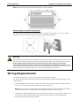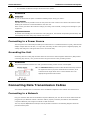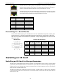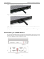
1
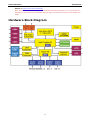
V2101 Series Hardware Manual Fifth Edition, October 2013 www.moxa.com/product © 2013 Moxa Inc. All rights reserved. V2101 Series Hardware Manual The software described in this manual is furnished under a license agreement and may be used only in accordance with the terms of that agreement. Copyright Notice © 2013 Moxa Inc. All rights reserved. Trademarks The MOXA logo is a registered trademark of Moxa Inc. All other trademarks or registered marks in this manual belong to their respective manufacturers. Disclaimer Information in this document is subject to change without notice and does not represent a commitment on the part of Moxa. Moxa provides this document as is, without warranty of any kind, either expressed or implied, including, but not limited to, its particular purpose. Moxa reserves the right to make improvements and/or changes to this manual, or to the products and/or the programs described in this manual, at any time. Information provided in this manual is intended to be accurate and reliable. However, Moxa assumes no responsibility for its use, or for any infringements on the rights of third parties that may result from its use. This product might include unintentional technical or typographical errors. Changes are periodically made to the information herein to correct such errors, and these changes are incorporated into new editions of the publication. Technical Support Contact Information www.moxa.com/support Moxa Americas Moxa China (Shanghai office) Toll-free: 1-888-669-2872 Toll-free: 800-820-5036 Tel: +1-714-528-6777 Tel: +86-21-5258-9955 Fax: +1-714-528-6778 Fax: +86-21-5258-5505 Moxa Europe Moxa Asia-Pacific Tel: +49-89-3 70 03 99-0 Tel: +886-2-8919-1230 Fax: +49-89-3 70 03 99-99 Fax: +886-2-8919-1231 Table of Contents 1. Introduction ...................................................................................................................................... 1-1 Overview ........................................................................................................................................... 1-2 Package Checklist ............................................................................................................................... 1-2 Product Features ................................................................................................................................ 1-2 V2101 Hardware Specifications............................................................................................................. 1-3 Hardware Block Diagram ..................................................................................................................... 1-5 2. Hardware Introduction...................................................................................................................... 2-1 Appearance........................................................................................................................................ 2-2 Dimensions ........................................................................................................................................ 2-2 LED Indicators .................................................................................................................................... 2-3 Reset Button ...................................................................................................................................... 2-3 Real Time Clock .................................................................................................................................. 2-3 3. Hardware Connection Description ..................................................................................................... 3-1 Installing the V2101 ............................................................................................................................ 3-2 Wiring Requirements ........................................................................................................................... 3-3 Connecting to a Power Source....................................................................................................... 3-4 Grounding the Unit ...................................................................................................................... 3-4 Connecting Data Transmission Cables ................................................................................................... 3-4 Connecting to a Network .............................................................................................................. 3-4 Connecting to a Serial Device ....................................................................................................... 3-5 Installing an SD Card .......................................................................................................................... 3-5 Installing an SD Card for Storage Expansion ................................................................................... 3-5 Connecting to a USB Device ................................................................................................................. 3-6 DI/DO ............................................................................................................................................... 3-7 Wiring Method ............................................................................................................................ 3-7 Connecting to a VGA Monitor................................................................................................................ 3-7 Connecting to an LVDS Monitor ............................................................................................................ 3-8 Connecting to a Speaker or a Headphone .............................................................................................. 3-8 4. BIOS Setup........................................................................................................................................ 4-1 Entering the BIOS Setup Utility ............................................................................................................ 4-2 Modifying the BIOS Main Settings ......................................................................................................... 4-2 Basic Configuration ...................................................................................................................... 4-2 System Security .......................................................................................................................... 4-2 Advanced Settings .............................................................................................................................. 4-3 Hard Disk Boot Priority ................................................................................................................. 4-3 Advanced BIOS Features .............................................................................................................. 4-3 CPU Features .............................................................................................................................. 4-3 Advanced Chipset Settings ........................................................................................................... 4-4 Peripherals......................................................................................................................................... 4-5 OnChip IDE Device ...................................................................................................................... 4-6 Onboard Device .......................................................................................................................... 4-6 Onboard I/O Chip Setup ............................................................................................................... 4-7 Power................................................................................................................................................ 4-9 Hardware Monitor ............................................................................................................................... 4-9 Load Defaults ................................................................................................................................... 4-10 Exiting the BIOS Setup ...................................................................................................................... 4-10 Upgrading the BIOS .......................................................................................................................... 4-11 A. Regulatory Approval Statement ........................................................................................................ A-1 1 1. Introduction V2101 embedded computers are based on the Intel Atom Z510PT x86 processor, and feature 2 serial ports, dual Gigabit LAN ports, 4 USB 2.0 hosts, and an SD socket. The V2101 series offers both VGA and LVDS outputs, making it particularly well-suited for industrial SCADA and factory automation roles. The V2101 computers’ 2 serial ports allow for linking to a wide range of serial devices, and the dual 10/100/1000 Mbps Ethernet ports offer a reliable solution for network redundancy, promising continuous operation for data communication and management. As an added convenience, V2101 computers have 3 digital inputs and three outputs, as well as SD and USB sockets for data buffering, mass storage devices, and other peripheral expansion alternatives. V2101 series computers come with a choice of pre-installed Linux, Windows CE 6.0, or Windows Embedded Standard 2009, allowing programmers to choose their preferred software environment for the development of application software. The following topics are covered in this chapter: Overview Package Checklist Product Features V2101 Hardware Specifications Hardware Block Diagram V2101 Hardware Introduction Overview V2101 embedded computers are based on the Intel Atom Z510PT x86 processor, and feature 2 serial ports, dual Gigabit LAN ports, 4 USB 2.0 hosts, and an SD socket. The V2101 series offers both VGA and LVDS outputs, making it particularly well-suited for industrial SCADA and factory automation roles. The V2101 computers’ 2 serial ports allow for linking to a wide range of serial devices, and the dual 10/100/1000 Mbps Ethernet ports offer a reliable solution for network redundancy, promising continuous operation for data communication and management. As an added convenience, V2101 computers have 3 digital inputs and three outputs, as well as SD and USB sockets for data buffering, mass storage devices, and other peripheral expansion alternatives. V2101 series computers come with a choice of pre-installed Linux, Windows CE 6.0, or Windows Embedded Standard 2009, allowing programmers to choose their preferred software environment for the development of application software. Wide temperature models that operate reliably in temperatures ranging from -40 to 85°C are also available, allowing for convenient deployments in extremely cold or hot industrial environments. Package Checklist The V2101 Series includes the following models: V2101-T-CE: x86 ready-to-run embedded computer with Intel Atom Z510PT, VGA, LVDS, audio, 2 RJ45 Gigabit Ethernet ports, 2 serial ports, 3 DIs, 3 DOs, 4 USB 2.0 ports, SD, WinCE 6.0, -40 to 85°C operating temperature. V2101-T-XPE: x86 ready-to-run embedded computer with Intel Atom Z510PT, VGA, LVDS, audio, 2 RJ45 Gigabit Ethernet ports, 2 serial ports, 3 DIs, 3 DOs, 4 USB 2.0 ports, SD, Win XPe SP3, -40 to 85°C operating temperature. V2101-T-LX: x86 ready-to-run embedded computer with Intel Atom Z510PT, VGA, LVDS, audio, 2 RJ45 Gigabit Ethernet ports, 2 serial ports, 3 DIs, 3 DOs, 4 USB 2.0 ports, SD, Linux 2.6, -40 to 85°C operating temperature. Each model ships with the following items: • V2101 Embedded Computer • Terminal Block to Power Jack Converter • DIN Rail Mounting Kit • Wall Mounting Kit • Quick Installation Guide • Document & Software CD or DVD • Product Warranty Statement (printed) NOTE: Please notify your sales representative if any of the above items are missing or damaged. Product Features V2101 series embedded computers have the following features: • Intel Atom Z510PT 1.1 GHz processor, 400 MHz FSB • DDR2 SODIMM socket, supporting DDR2 400 up to 2 GB • Dual independent displays (VGA + LVDS) • 2 Gigabit Ethernet ports • 4 USB 2.0 ports for high speed peripherals • 3 DIs and 3 Dos 1-2 V2101 Hardware Introduction • 2 RS-232/422/485 ports • CompactFlash socket for storing OS • 4 USB 2.0 hosts supporting system boot up • Ready-to-run Embedded Linux, Windows CE 6.0, or Windows XPe platform • -40 to 85°C wide operating temperature models for harsh environments V2101 Hardware Specifications Computer CPU: Intel Atom Z510PT 1.1 GHz processor OS (pre-installed): Linux, Windows CE 6.0 or Windows Embedded Standard 2009 System Chipset: Intel US15WPT BIOS: 8 Mbit Flash BIOS, ACPI function supported (XPe model only) FSB: 400 MHz System Memory: 1 x 200-pin DDR2 SODIMM socket support DDR2 400 up to 2GB max, 1 GB built-in USB: USB 2.0 compliant hosts x 4, type A connector, supports system boot up Storage Built-in: 2 GB CompactFlash to store OS Storage Expansion: SD socket for storage expansion Other Peripherals Audio: AC97 audio, with line-in and line-out interface Display Graphics Controller: Intel Graphics Media Accelerator, 500 Graphics, for 2D and 3D graphics Video: The Poulsbo XL SCH supports full hardware acceleration of video decode standards such as H.264, MPEG2, MPEG4, and WMV9. SDVO: Chrontel CH7317 for VGA output (1280 x 1024 @ 85 Hz) VGA Interface: DB15 female connector LVDS Interface: 18-bit or 24-bit single channel LVDS (1366 x 768 @ 85 Hz) Ethernet Interface LAN: 2 auto-sensing 10/100/1000 Mbps ports (RJ45) Serial Interface Serial Standards: 2 RS-232/422/485 ports, software selectable (DB9 male) ESD Protection: 2 KV for all signals Serial Communication Parameters Data Bits: 5, 6, 7, 8 Stop Bits: 1, 1.5, 2 Parity: None, Even, Odd, Space, Mark Flow Control: RTS/CTS, XON/XOFF Baudrate: 50 bps to 115.2 Kbps Serial Signals RS-232: TxD, RxD, DTR, DSR, RTS, CTS, DCD, GND RS-422: TxD+, TxD-, RxD+, RxD-, GND RS-485-4w: TxD+, TxD-, RxD+, RxD-, GND RS-485-2w: Data+, Data-, GND Digital Input Input Channels: 3, source type Input Voltage: 0 to 30 VDC at 5 KHz Digital Input Levels for Dry Contacts: • Logic level 0: Close to GND • Logic level 1: Open 1-3 V2101 Hardware Introduction Digital Input Levels for Wet Contacts: • Logic level 0: +3 V max. • Logic level 1: +10 V to +30 V (COM to DI) Connector Type: DB9 female Digital Output Output Channels: 3, sink type Output Current: Max. 200 mA per channel Output Voltage: • Logic 0: 0-0.55 V • Logic 1: 2.5-3.3 V On-state Voltage: 24 VDC nominal, open collector to 30 V Connector Type: DB9 female LEDs System: Power, Storage LAN: 100M/Link x 2, 1000M/Link x 2 (on connector) Serial: Tx, Rx Switches and Buttons Power Switch: on/off (side) Reset Button: For warm reboot (front side) Physical Characteristics Housing: Aluminum Weight: 940 g Dimensions: Without ears: 150 x 49 x 125 mm (5.91 x 1.93 x 4.92 in) With ears: 178 x 52 x 125 mm (7.01 x 2.05 x 4.92 in) Mounting: DIN-Rail, wall, VESA Environmental Limits Operating Temperature: -40 to 85°C (-40 to 185°F) Storage Temperature: -40 to 85°C (-40 to 185°F) Ambient Relative Humidity: 5 to 95% (non-condensing) Anti-vibration: 2 g rms @ IEC-68-2-34, random wave, 5-500 Hz, 1 hr per axis Anti-shock: 20 g @ IEC-68-2-27, half sine wave, 11 ms Power Requirements Input Voltage: 9 to 36 VDC (3-pin terminal block for V+, V-, SG) Power Consumption: (without LVDS output) With no load on 4 USB ports: • 1.88 A @ 9 VDC, 17 W • 583 mA @ 24 VDC 14 W • 422 mA @ 36 VDC 15 W With full load on 4 USB ports: • 3 A @ 9 VDC, 27 W • 1 A @ 24 VDC, 24 W • 700 mA @ 36 VDC, 25.2 W Standards and Certifications Safety: UL 508, UL 60950-1, CSA C22.2 No. 60950-1-07, EN 60950-1, CCC (GB9254, GB17625.1) EMC: EN 55022 Class A, EN 61000-3-2 Class D, EN 61000-3-3, EN 55024, FCC Part 15 Subpart B Class A Green Product: RoHS, cRoHS, WEEE Reliability Automatic Reboot Trigger: Built-in WDT (watchdog timer) supporting 1-255 level time interval system reset, software programmable MTBF (mean time between failures): 231,633 hrs hrs Warranty Warranty Period: 3 years 1-4 V2101 Hardware Introduction Details: See http://www.moxa.com/warranty Note: The Hardware Specifications apply to the embedded computer unit itself, but not to accessories. In particular, the wide temperature specification does not apply to accessories such as the power adaptor and cables. Hardware Block Diagram 1-5 2 2. Hardware Introduction The V2101 series of embedded computers are compact, well-designed, and built rugged enough for industrial applications. LED indicators help you monitor performance and identify trouble spots, multiple serial ports allow you to connect different devices for wireless operation, and the reliable and stable hardware platform lets you devote your attention to developing your applications. The following topics are covered in this chapter: Appearance Dimensions LED Indicators Reset Button Real Time Clock V2101 Hardware Hardware Introduction Appearance V2101 Front View Side View Rear View Dimensions V2101 Unit: mm 2-2 V2101 Hardware Hardware Introduction LED Indicators LED Name Power Storage LAN LED Color Green Off Yellow Off Power is on and functioning normally No power is getting to the system: power is off or has failed. SD card is detected SD card is not detected Green 100 Mbps Ethernet mode Yellow 1000 Mbps (Gigabit) Ethernet mode Off Tx1, Tx2 LED Function Green (P1-P2) Off Rx1, Rx2 Yellow (P1-P2) Off No activity or 10 Mbps Ethernet mode Serial ports P1-P2 transmitting data Serial ports P1-P2 not transmitting data Serial ports P1-P2 receiving data Serial ports P1-P2 not receiving data Reset Button Press the Reset Button on the front panel of the V2101 for a soft reboot of the system. The Ready LED will blink on and off for the first 5 seconds, and then maintain a steady glow once the system has completed rebooting. The V2101 does not support a Reset to Default function. Real Time Clock The embedded computer’s real-time clock is powered by a lithium battery. We strongly recommend that you do NOT replace the lithium battery on your own. If the battery needs to be changed, please contact the Moxa RMA service team. ATTENTION There is a risk of explosion if an incompatible battery is used to replace the lithium clock battery. To avoid this potential danger, always be sure to use the correct type of battery. Contact the Moxa RMA service team if you need to replace your battery. Please dispose of used batteries according to best practices for hazardous and toxic materials. 2-3 3 3. Initial Hardware and Peripheral Setup V2101 embedded computers provide multiple communication interfaces, including serial, USB, and DI/DO channels. In addition, the computers provide either a VGA or LVDS output for field site monitoring. In this chapter, we show how to connect the embedded computers to the network over their various peripheral interfaces. The following topics are covered in this chapter: Installing the V2101 Wiring Requirements Connecting to a Power Source Grounding the Unit Connecting Data Transmission Cables Connecting to a Network Connecting to a Serial Device Installing an SD Card Installing an SD Card for Storage Expansion Connecting to a USB Device DI/DO Wiring Method Connecting to a VGA Monitor Connecting to an LVDS Monitor Connecting to a Speaker or a Headphone V2101 Hardware Hardware Connection Description Installing the V2101 DIN Rail Mounting Step 1: Use two screws to attach the DIN-rail attachment plate to the bottom of the V2101. When attaching the plate to the V2101, make sure that the stiff metal spring is at the top. Step 2: Insert the top of the DIN rail into the slot just Step 3: The DIN rail attachment unit will snap into below the stiff metal spring. place as shown below. Wall or Cabinet Mounting The V2101 comes with two metal brackets for attaching it to a wall or the inside of a cabinet. Step 1: Use two screws for each bracket and attach the bracket to the rear of the V2101. 3-2 V2101 Hardware Hardware Connection Description Step 2: Use two screws per side to attach the V2101 to a wall or cabinet. VESA Mounting (not included in the Package) The V2101 has four screw holes on the bottom panel for attaching the computer to a 75 x 75 mm VESA mounting kit. Use four screws to attach the computer to the VESA mounting kit. Warning The screw holes for the mount points are approximately 3 mm deep. Users should take extreme care to ensure that any screws used to mount the enclosure do not penetrate more than 1 mm into the device enclosure. Screws which penetrate more than 1 mm into the enclosure may come into contact with components on the PCB, shorting out the device and permanently damaging the internals. Taking the 3 mm depth of the mounting holes, plus 1 mm of internal leeway, any screws used to mount the V2101 should penetrate no more than a total of 4 mm beyond the external face of the device. Wiring Requirements This section describes how to connect serial devices to the embedded computer. You should read and follow these common safety precautions before proceeding with the installation of any electronic device: • Use separate paths to route wiring for power and devices. If power wiring and device wiring paths must cross, make sure the wires are perpendicular at the intersection point. NOTE: Do not run signal or communication wiring together with power wiring in the same wire conduit. To avoid interference, wires with different signal characteristics should be routed separately. • Use the type of signal transmitted through a wire to determine which wires should be kept separate. The rule of thumb is that wiring that shares similar electrical characteristics can be bundled together. • Keep input wiring and output wiring separate. 3-3 V2101 Hardware • Hardware Connection Description It is advisable to label the wiring to all devices in the system. ATTENTION Safety First! Be sure to disconnect the power cord before installing and/or wiring your V2101. Wiring Caution! Calculate the maximum possible current in each power wire and common wire. Observe all electrical codes dictating the maximum current allowable for each wire size. If the current goes above the maximum ratings, the wiring could overheat, causing serious damage to your equipment. Temperature Caution! Be careful when handling the unit. When the unit is plugged in, the internal components generate heat, and consequently the outer casing may feel hot to the touch. Connecting to a Power Source The PC’s power source should be provided by a UL listed class 2 or “Limited Power Source” (LPS), with external adaptor output rated 9 to 36 VDC, 1.8 A @ 9 VDC, 422 mA @ 36 VDC. If the power is supplied properly, the “Ready” LED will glow a solid green after a 25 to 30 second delay. Grounding the Unit Grounding and wire routing help limit the effects of noise due to electromagnetic interference (EMI). Before connecting any devices, run a ground wire from the ground screw to the grounding surface. ATTENTION This product should be mounted to a well-grounded mounting surface such as a metal panel. SG: The Shielded Ground (sometimes called Protected Ground) contact is the rightmost of the 3-pin power terminal block connector, when viewed from the angle shown here. Connect the SG wire to an appropriate grounded metal surface. Connecting Data Transmission Cables This section describes how to connect the V2101 embedded computers to the network and serial devices. Connecting to a Network Plug your network cable into the embedded computer’s Ethernet port. The other end of the cable should be plugged into your Ethernet network. When the cable is properly connected, the LEDs on the embedded computer’s Ethernet port will glow to indicate a valid connection. The 10/100/1000 Mbps Ethernet LAN port uses 8-pin RJ45 connectors. The following diagram shows the pinouts for these ports. 3-4 V2101 Hardware Hardware Connection Description The LED indicators on the right top and right bottom corners glow a solid green color when the cable is properly connected to a 100 Mbps Ethernet network. The LED will flash on and off when Ethernet packets are being transmitted or received. The LED indicators on the left top and left bottom corners glow a solid yellow color when the cable is properly connected to a 1000 Mbps Ethernet network. The LED will flash on and off when Ethernet packets are being transmitted or received. Pin 10/100 Mbps 1000 Mbps 1 ETx+ TRD(0)+ 2 ETx- TRD(0)- 3 ERx+ TRD(1)+ 4 --- TRD(2)+ 5 --- TRD(2)- 6 ERx- TRD(1)- 7 --- TRD(3)+ 8 --- TRD(3)- Connecting to a Serial Device Use a serial cable to plug your serial device into the embedded computer’s serial port. Serial ports P1 to P2 have male DB9 connectors and can be configured for RS-232, RS-422, or RS-485 communication by software. The pin assignments are shown in the following table: DB9 Male Port RS-232/422/485 Pinouts RS-485 RS-485 (4-wire) (2-wire) TxDA(-) --- Pin RS-232 RS-422 1 DCD TxDA(-) 2 RxD TxDB(+) TxDB(+) --- 3 TxD RxDB(+) RxDB(+) DataB(+) 4 DTR RxDA(-) RxDA(-) DataA(-) 5 GND GND GND GND 6 DSR --- --- --- 7 RTS --- --- --- 8 CTS --- --- --- Installing an SD Card Installing an SD Card for Storage Expansion The V2101 has an internal SD slot for storage expansion. The SD slot allows users to plug in a Secure Digital (SD) memory card compliant with the SD 1.0 standard for up to 1 GB space, and a Secure Digital High Capacity (SDHC) memory card compliant with the SD 2.0 standard for up to 16 GB of additional memory. The following steps show how to install the SD card. The SD slot is located in the middle of the V2101’s front panel. To install an SD card, make sure the embedded computer is powered off, remove the protective cover from the left to access the slot, and then plug the SD card directly into the slot. 3-5 V2101 Hardware Hardware Connection Description Step 1: Gently remove the outer cover from the left. Step 2: After removing the cover, insert the SD memory card into the slot. Step 3: Gently move the protective cover back to the SD slot. Power on the embedded computer and start the operating system. NOTE: To remove the SD card from the slot, press the SD card in slightly with your finger, and then remove your finger to allow the card to spring out partially. You may now grasp the top of the card with two fingers and pull it out. Connecting to a USB Device The V2101 comes with 4 USB 2.0 hosts. One is located on the front panel and the other three are on the rear panel. The hosts can be used for an external flash disk or hard drive for storing large amounts of data. You can also use these USB hosts to connect to a keyboard or a mouse. 3-6 V2101 Hardware Hardware Connection Description DI/DO The V2101 comes with a 3-ch digital input and a 3-ch digital output through a DB9 female connector. The pin assignments are shown below. PIN Signal 1 COM 2 DO 1 3 N/A 4 DI 1 5 GND 6 DO 0 7 DO2 8 DI 0 9 DI 2 Digital Input / Output Wiring Methods Please refer to the following figures for digital input / output wiring methods of the V2101. Connecting to a VGA Monitor The V2101 comes with a D-Sub 15-pin female connector on the rear panel to connect a VGA CRT monitor. To ensure that the monitor image remains clear, be sure to tighten the monitor cable after connecting it to the V2101. The pin assignments of the VGA connector are shown below. DB15 Female Connector Pin No. Signal Definition 1 Red 2 Green 3 Blue 4 NC 5 GND 6 GND 7 GND 8 GND 9 VCC 10 GND 11 NC 12 DDC2B Data 13 HSYNC 14 VSYNC 15 DDC2B Clock 3-7 V2101 Hardware Hardware Connection Description Connecting to an LVDS Monitor The V2101 also comes with a 26-pin LVDS connector on the side panel to connect a panel with an LVDS cable. The pin assignments of the LVDS connector are shown below. LVDS Female Connector Pin No. Signal Definition 1 VDD_12V 2 GND 3 LVDS_CLK_N 4 LVDS_DAT_P3 5 GND 6 LVDS_DAT_N2 7 LVDS_DAT_P1 8 GND 9 LVDS_DAT_N0 10 VDD_12V 11 N/C 12 LVDS_CLK_P 13 GND 14 LVDS_DAT_N3 15 LVDS_DAT_P2 16 GND 17 LVDS_DAT_N1 18 LVDS_DAT_P0 19 VDD_5V 20 VDD_5V 21 VDD_3V3 22 VDD_3V3 23 GND 24 BKLT_EN 25 L_DDC_CLK 26 L_DDC_DAT Connecting to a Speaker or a Headphone The V2101 comes with audio input and output jacks for connecting a microphone and speaker or headphones. See the following figure for details. 3-8 4 4. BIOS Setup This chapter describes the BIOS settings of the V2101 embedded computers. The BIOS is a set of input/output control routines for peripherals. The BIOS is used to initialize basic peripherals and helps boot the operating system before the operating system is loaded. The BIOS setup allows the user to modify the system configurations of these basic input/output peripherals. All of the configurations will be stored in the battery backed up CMOS RAM, which retainsthe system information after system reboots or the power is removed. The following topics are covered in this chapter: Entering the BIOS Setup Utility Modifying the BIOS Main Settings Basic Configuration System Security Advanced Settings Hard Disk Boot Priority Advanced BIOS Features CPU Features Advanced Chipset Settings Peripherals OnChip IDE Device Onboard Device Onboard I/O Chip Setup Power Hardware Monitor Load Defaults Exiting the BIOS Setup Upgrading the BIOS V2101 Hardware BIOS Setup Entering the BIOS Setup Utility To enter the BIOS setup utility, press the “Del” key while the system is booting up. The main BIOS Setup screen will appear. A basic description of each function key is listed at the bottom of the screen. Refer to these descriptions to learn how to scroll about the screen, how to select by pressing “Enter,” and how to use the other hot keys listed below. F1: General Help F7: Turbo Settings F5: Previous Value F10: Save F6: Default Settings ESC: Exit Modifying the BIOS Main Settings Basic Configuration After entering the BIOS Setup, or choosing the “Main” option, the BIOS main menu will be displayed. Use this menu to check the basic system information such as memory and IDE hard drive. You can also use the menu for configuring basic system parameters, such as date, time, hard drive, display, and system security. System Security To set up system security, select the “Security” option under “Main” to bring up the following screen. This menu includes two options: “Set Password” and “Security Option.” When you select the Set Password option, a pop-up “Enter Password:” window will appear on the screen. The password that you type will replace the password stored in the CMOS memory. You will be required to confirm the new password. Just re-type the password and then press <Enter>. You may also press <Enter> to abort the selection and not enter a password. To clear an existing password, just press <Enter> when you are prompted to enter the password. A message will show up confirming that the password will be disabled. Once the password is disabled, the system will boot and you can enter the “BIOS Setup Menu” without entering a password. Once a password has been set, you will be prompted to enter the password each time you enter Setup. This prevents unauthorized persons from changing any part of your system configuration. In addition, when a password setting is enabled, you can set up the BIOS to request a password each time the system is booted up. The “Security Option” setting determines when a password prompt is required. If the “Security Option” is set 4-2 V2101 Hardware BIOS Setup to “System,” the password must be entered both at boot up and when entering the BIOS Setup Menu. If the password is set for “Setup,” the password prompt only occurs when you enter the “BIOS Setup Menu.” Advanced Settings The “Advanced Features” screen will appear when choosing the “Advanced” item from the main menu. Hard Disk Boot Priority First/Second/Third Boot Device This option allows users to select or change the device boot priority. You may set 3 levels of priority to determine the boot up sequence for different bootable devices, such as a hard drive, CD-ROM, and removable devices. Select the order in which devices will be searched in order to find a boot device. The available options are “CDROM (default for first boot device),” “Removable” (default for third boot device), “Hard Disk” (default for second boot device) and “Disabled.” Advanced BIOS Features When you select the “Advanced BIOS Features” option under the “Advanced” menu, the following configuration menu will appear. CPU Features C1E Function This item allows you to configure the power-saving mode when the CPU is in C1 status. Options: Disabled (default), Auto CPU C State Capability This item allows you to configure the power saving mode when the CPU is in C2, C4, or C6 status. Options: Disabled (default), C2, C4, C6 4-3 V2101 Hardware BIOS Setup CPU L1 & L2 Cache Make the CPU internal cache active or inactive. System performance may degrade if you disable this item. Options: Enabled (default), Disabled. Hyper-Threading Technology This item allows you to enable or disable the hyper-threading function, which allows the system to handle more than one thread at the same time. Options: Disabled (default), Enabled Advanced Chipset Settings On-chip Frame Buffer Size This item determines the frame buffer size for the VGA function, and will share the system memory. Options: 1 MB, 4 MB, 8 MB (default), 4-4 V2101 Hardware BIOS Setup Boot Type This item determines the boot type of the display. Select either CRT or LVDS. Options: CRT (default), LVDS LCD Panel Type This item allows you to choose the resolution of the panel. From the list, select the correct resolution of your panel. Default: 1024x768 generic Panel Scaling This item allows you to zoom in and zoom out with the same ratio of the panel. Options: Auto (default), Force, Off Panel Data Format Select This item allows to select the data format according to the LVDS display. Options: 24 bit (default), 18 bit ATTENTION Note that you must select the correct resolution for your LVDS display based on your LVDS specifications, or it will not be properly shown on your panel. When you encounter this problem, take the following steps: 1. Press the Insert key after you hear the beep. 2. Restart your computer and press the Del key while the system is booting up. 3. Reconfigure the VGA setting in the BIOS menu and select the correct resolution and data format for your LVDS Peripherals 4-5 V2101 Hardware BIOS Setup OnChip IDE Device IDE HDD Block Mode Block mode is otherwise known as block transfer, multiple commands, or multiple sector read/write. Select the “Enabled” option if your IDE hard drive supports block mode (most new drives do). The system will automatically determine the optimal number of blocks to read and write per sector. Options: Enabled (default), Disabled IDE Primary Master UDMA This item allows you to select the UDMA value for the primary Master Disk. Options: Auto (default), Disabled, UDMA33, UDMA66, UDMA100 Onboard Device Intel HD Audio Controller This feature allows you to enable/disable the HD audio controller. Options: Auto (default), Disabled SDIO/MMC Controller This feature allows you to enable/disable the SD controller. Options: Enabled (default), Disabled SD Boot ROM Decide whether to invoke the boot ROM of SDIO interface. 4-6 V2101 Hardware BIOS Setup Options: Disabled (default), Enabled (Note: DOS, Linux, and Windows 7 Embedded allow booting from SD card. For further information, please contact Moxa for technical support) Onboard LAN Boot ROM Decide whether to invoke the boot ROM of the onboard LAN chip. Options: Enabled, Disabled (default) Onboard I/O Chip Setup Onboard Serial Port 1 This function allows you to enable/disable serial port 1 communication. The V2101 computer will automatically distribute the IRQ value for serial port 1 as the default value. If you wish to disable, select Disabled. 4-7 V2101 Hardware BIOS Setup Onboard Serial Port 2 This function allows you to enable/disable serial port 2 communication. The V2101 computer will automatically distribute the IRQ value for serial port 2 as the default value. If you wish to disable, select Disabled. Debug Port This function allows you to enable/disable the debug port communication. The V2101 computer will automatically distribute the IRQ value for the debug port as the default value. If you wish to disable, select Disabled. This port is only for engineers who are debugging programs. 4-8 V2101 Hardware BIOS Setup Power The Power Setup Menu allows you to configure your system power-up/ power-down options. HPET Support This feature allows you to enable/disable the HPET (High Precision Event Timer) function. Option: Disabled, Enabled (default) Hardware Monitor This item helps monitor the status of the system, including CPU temperature and the voltage of the CPU, SDRAM and battery. 4-9 V2101 Hardware BIOS Setup Load Defaults Load System Default Settings Use this option to load system factory default settings instead of the current BIOS settings. This option is useful for when the system is unstable. Users do not need to remember what settings were active before the system fails. Load System Turbo Settings Use this option to load system optimized settings. If the system is not stable, please load the system default settings. Load CMOS from BIOS Use this option to load BIOS settings from flash ROM to CMOS. Save CMOS to BIOS Use this option to save the BIOS settings from the CMOS to flash ROM. Exiting the BIOS Setup To exit the BIOS setup utility, choose “Exit.” Pressing <ESC> will achieve the same result. Save & Exit Setup Save all configuration changes to CMOS (memory) and exit setup. A confirmation message will be displayed before proceeding. 4-10 V2101 Hardware BIOS Setup Exit Without Saving Abandon all changes made during the current session and exit setup. A confirmation message will be displayed before proceeding. Upgrading the BIOS This section describes how to upgrade the BIOS. However, please note that upgrading the BIOS involves high risk of damage to your computer. We strongly recommend that you contact Moxa’s TS staff for assistance and obtain all necessary tools and files before attempting to upgrade. Step 1: Create a Bootable USB Disk. We suggest you use the HP USB Disk Format Tool to create a bootable USB disk. You may download this tool from the Internet. Search the Internet using the phrase “HP USB Disk Storage Format Tool”, and then download the tool from one of the listed websites. You will also need to download the FreeDos system files kernel.sys and command.com from http://www.freedos.org/kernel/. 1. Copy DOS system files kernel.sys and command.com to a specified directory (C:\FreeDOS in this example). 2. Start the HP USB Disk Storage Format Tool and select the USB device that you want to use as a bootable disk in the Device drop down box. 3. Select FAT in the File system drop down box. 4. Type the disk name in the Volume label field. 5. Check the option Create a DOS startup disk under format options. 6. Specify the directory of the system files (for example, C:\FreeDOS). 7. Click Start to format and create the USB disk. 4-11 V2101 Hardware BIOS Setup ATTENTION We suggest you use a USB drive with under 2 GB in disk space, as larger USB drives may not support FAT file format and consequently fail to boot. Step 2: Prepare the Upgrade Tool and BIOS Binary File. You must use the BIOS upgrade installation file to upgrade the BIOS. You can download it from the Moxa Download Center at: http://web4.moxa.com/support/download_center.asp 1. Get the BIOS upgrade installation file. The file name should have following format: 210010.s00. 2. Copy the file to the Bootable USB Disk. 3. Double click to extract the BIOS update installation file. The file includes a binary file in the form s210010.s00 and the upgrade utility named awdflash.exe. Step 3: Set up the BIOS to Boot from the USB Disk. 1. Insert the USB disk. 2. Power on and press DEL to enter the BIOS Setup menu. 3. Select Advanced Hard Disk Boot Priority and then press Enter. 4. From the Setup menu, use “↑” or “↓” to select the USB device. 4-12 V2101 Hardware BIOS Setup 5. Press “+” to move it up to the first priority, and press “Esc” to exit the setup menu. 6. Make sure the first boot device is Hard Disk. If it isn’t, press Enter to change it. 7. Select Exit Save & Exit Setup and then press Enter. 8. Choose Y to save to the CMOS and then exit. (instructions continue on next page) 4-13 V2101 Hardware BIOS Setup Step 4: Run awdflash.exe to upgrade the BIOS. 1. While in the BIOS Setup menu and before upgrading the BIOS, you may choose to save the old BIOS files to a specific location. Type Y to do so, or N to begin the upgrade. 2. If the BIOS Setup is correct, it will restart and boot from the USB disk. 3. Run awdflash 210010.S00 from the command line to upgrade the BIOS. Replace xxxxxxx.Sxx with the BIOS binary file name discussed in Step 2. 4. Press F1 to reset the system after the bios update is complete. The system should reboot at this time. 5. Please note that once the BIOS is successfully upgraded, the default BIOS values will be automatically loaded. However, if you wish to re-configure the BIOS settings, press DEL while booting. ATTENTION Do NOT switch off the power supply during the BIOS upgrade, since doing so may cause the system to crash. 4-14 A A. Regulatory Approval Statement This device complies with part 15 of the FCC Rules. Operation is subject to the following two conditions: (1) This device may not cause harmful interference, and (2) this device must accept any interference received, including interference that may cause undesired operation. Class A: FCC Warning! This equipment has been tested and found to comply with the limits for a Class A digital device, pursuant to part 15 of the FCC Rules. These limits are designed to provide reasonable protection against harmful interference when the equipment is operated in a commercial environment. This equipment generates, uses, and can radiate radio frequency energy and, if not installed and used in accordance with the instruction manual, may cause harmful interference to radio communications. Operation of this equipment in a residential area is likely to cause harmful interference in which case the user will be required to correct the interference at his own expense. European Community Warning: This is a class A product. In a domestic environment this product may cause radio interference in which case the user may be required to take adequate measures.