1
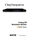
8 Channel Intelligent Loudness Meter
iLM8
User Manual
Welcome
Thanks for purchasing the DaySequerra iLM8. Differences in audio levels between TV programs, or
between programs and commercials, are a constant annoyance to viewers. iLM8 permits broadcasters
to verify compliance of their desired loudness level across all audio programming and minimize viewer
complaints.
We design and build all of our DaySequerra products to be completely reliable and easy to use, so you
can concentrate on producing great sounding broadcasts, not struggling with complicated equipment or
difficult to use product manuals.
While the iLM8 has been designed to be straightforward to use, we do suggest that you spend a few
minutes familiarizing yourself with the features and operational functions that are contained in this
manual.
DaySequerra has been building broadcast quality products since 1989. The technology
developed for the iLM8, and all of our products, has evolved through a process of user
feedback, extensive listening, field-testing and careful refinement.
In the event that you encounter any technical or operational difficulties with this or any DaySequerra
product, please feel free to contact us at 856-719-9900. Our office hours are from 9 to 5 ET, Monday
through Friday; or you can email your questions to: [email protected].
Also, please remember to visit our website www.daysequerra.com for warranty registration and the
latest DaySequerra product information.
We have worked hard to ensure that your DaySequerra iLM8 will reliably serve you for years to come.
With a modular design and upgradeable firmware, your new unit is easy to install and use right out of
the box.
We sincerely hope our products help you achieve a new level of excellence in your work!
David V. Day
and the DaySequerra Team
2
iLM8 User Manual
Table of Contents
Important Safety Information
4
Menu Functions and Descriptions
19
Service Information
4
Faults
26
Technical Specifications
5
Firmware Update
27
Introduction
6
iLM8 Remote Dashboard
28
Measuring Loudness
7
Remote Dashboard Configuration
29
Using iLM8 to Control Loudness
10
Using Remote Dashboard
31
Installation
12
Log Files
32
Front Panel
13
Maintaining an Accurate Clock
33
Rear Panel
14
Remote Dashboard Troubleshooting
33
Meter Display
16
Warranty
35
Home Screen
17
Programming Menu
18
Menu Tree
18
iLM8 Key Features
•
Standalone operation – no external encoder is required
•
Industry-standard ITU-R BS.1770/1 and Leq(A), Leq(B), Leq(C), Leq(M) weighted
measures along with the DTS-Neural Loudness Measure (NLM) algorithm;
simultaneous measurement for 5.1 surround and auxiliary stereo inputs
•
Robust DSP platform – no PC operating system to hang; no lengthy boot-ups
•
Easy-to-read numerical Measured and Target readouts on vacuum fluorescent display;
bar graph LED audio level meters and exclusive Mix Monitor indicators
•
Front panel headphone monitor
•
Ethernet interface for long-term logging and field software updates
•
Optional HD/SDI and Balanced Digital AES I/O
All rights reserved DaySequerra Corp. Copyright 2010.
All logos and trademark used herein are the property of their respective owners.
Specifications subject to change.
iLM8 User Manual Revision B for firmware 4.01.00.
iLM8 User Manual
3
Important Safety Information
•
•
•
•
•
•
•
•
•
•
Indoor use only. Not for use in wet or damp environments
Maximum Relative Humidity: <80%
Class I Equipment (grounded type)
Electrical rating: 100-260V~50-60Hz 25W max
Internal circuit breaker for continuous short circuit protection
AC Mains supply voltage fluctuations are not to exceed +10% of the nominal voltage
Operations temperature range -40°C to 70°C
Maximum altitude: 3000m (9843ft)
Equipment suitable for continuous operation
Weight: 3.6kg (8lbs) equipment only; 5.4kg (12.0lbs) shipping
Important Note: Please connect your iLM8 to an uninterruptible power supply (UPS) to provide
other protection against power surges and low-voltage conditions.
If iLM8 is subjected to a strong RFI field, such as those emitted from portable two way radios,
the display may “blank out”. To restore the display without rebooting the unit, turn the rotary
encoder to activate the main menu, and then press HOME. If the keylock is enabled, you will
have to deactivate it by pressing the ENTER key followed by BACK.
Service Information
The DaySequerra iLM8 contains no user serviceable components inside the unit. Please contact
DaySequerra for repair and upgrade information. In the event that your unit needs to be returned to the
factory, contact us for a return authorization number.
Please visit www.daysequerra.com and
register your new iLM8 so we can keep you informed of the latest hardware and software
updates.
The lightning flash with arrowhead symbol is intended to alert the user to the presence of uninsulated “dangerous voltages” within the product’s enclosure that may be of a sufficient level
to cause harm.
The exclamation point within a triangle is intended
to alert the user to the presence of important
operating and maintenance instructions within the
product literature.
Exposed portions of the power supply assembly are
electrically live. To reduce risk of electric shock, the
power cord must be disconnected when the power
supply assembly is removed. For continued
protection against electric shock, a correctly wired
and grounded (earthed) three-pin power outlet must
be used. Do not use a ground-lifting adapter and
never cut the ground pin on the three-prong plug.
The ground terminal of the power plug is connected
directly to the chassis of the unit.
4
iLM8 User Manual
Technical Specifications
Power Consumption:
Dimensions:
Sample Rate:
Loudness Algorithms:
Headphone Monitor:
GPIO:
Regulatory:
25W Maximum
Rack Mount; 1 RU (1.75” x 19” x 10.75”)
32kHz-96kHz, 24-bit
ITU-R BS.1770/1 (LKFS), DTS Neural Loudness
Measure (NLM), Leq(A), Leq(B), Leq(C), Leq(M)
3.5mm TRS connector, >150mW max into 32Ω load
DB-9 Female, 0-5V TTL opto-isolated
North America: Designed to comply with FCC Class
A part 15 requirements
Europe: Designed to comply with LV Directive
73/23/EEC and EMC Directive 89/336/EEC; CE Mark
(EN 55022 Class A, EN55024); Designed for RoHS
and WEEE compliance
FCC Part 15 Regulatory Statement
This equipment has been tested and found to comply with the limits for Class A digital device pursuant
to Part 15 of the FCC Rules. These limits are designed to provide reasonable protection against
harmful interference when the equipment is operated in a commercial environment. This equipment
generates, uses, and can radiate radio frequency energy and, if not installed and used in accordance
with the user manual, may cause interference to radio communications. Operation of this equipment in
a residential area is likely to cause interference in which case the user will be required to correct the
interference at their own expense. The user is cautioned that changes and modifications made to the
equipment without approval of the manufacturer could void the user's authority to operate this
equipment. The user should use only shielded and/or grounded cables to combat sources of
interference.
Environmental Preservation Efforts
This equipment has been designed and built by DaySequerra corporation to give many
years of trouble free service and is backed by our three year warranty and commitment
of providing the best customer support. When the time comes to retire your product from
service, it should be disposed of in accordance with local codes or ordinances. Do not
discard with household or commercial waste.
DaySequerra products are manufactured with the environment in mind. The directive on
the restriction of the use of certain hazardous substances in electrical and electronic
equipment (2002/95/EC) restricts the use of six specific hazardous materials in the
manufacture of various types of electronic and electrical equipment. Following this
directive prevents these toxic substances from entering our environment after disposal.
iLM8 User Manual
5
Introduction
Broadcasters need a solution to effectively measure, and ultimately control the abrupt changes in
loudness that sends viewers diving for their remote controls during commercial breaks and action
scenes. DaySequerra’s iLM8 Intelligent Loudness Meter measures perceived loudness of up to eight
channels of program audio using the industry-standard ITU-R BS.1770/1 loudness measure, along with
the DTS-Neural Loudness Measure (NLM) algorithm and the weighted intensity measures Leq(A),
Leq(B), Leq(C) and Leq(M).
Loudness is a perceptual property of an audio signal when it is reproduced acoustically. It is a complex
non-linear function of amplitude, frequency and bandwidth. Current audio level meters measure the
level of audio signals expressed as the amplitude of the signal - either the RMS (root mean square)
voltage of an electrical signal or the sound pressure of an acoustical signal. Neither of these
measurements, although widely accepted, provides accurate indications of how viewers will perceive
the loudness of the audio programming.
The DTS NLM algorithm uses a perceptual model of human hearing to more accurately detect spectral
and density differences, inter-channel relationships and temporal overlaps in any audio content,
resulting in a more accurate perceived loudness measurement over time. This proprietary algorithm
was developed by after extensive research into human hearing and perceived loudness.
The iLM8 measures the perceived loudness of eight channels of program audio and displays the results
in an easy-to-read numerical format with a moving average over time, eliminating the variations with
engineers interpreting traditional VU or PPM indicators (neither of which can measure perceived
loudness).
To improve system reliability and up-time, iLM8 uses a robust DSP-based processing platform rather
than a PC-based approach to completely avoid broadcast disruptions caused by operating system
lockups. The iLM8’s built-in high-performance headphone amplifier allows monitoring of any two userselected output pairs even in noisy background environments. An Ethernet interface provides long-term
logging and field software updates capability. The exclusive DaySequerra Mix Monitor provides instant
positive feedback if the audio is within target range. An optional factory-installed HD/SDI module will
allow for measurement of 8 channels of program audio from group 1 or group 2 with user specified
mappings within the group.
Whether pre-screening content at an ingest point or keeping tabs on the output of a broadcast airchain, iLM8 is your key to reduce viewer complaints and improve overall audience satisfaction.
6
iLM8 User Manual
Measuring Loudness
Human perception of the sensation of an audio signal is properly called “loudness”. As early as 1933,
research by Fletcher and Munson showed that human hearing sensitivity is largely based upon the
frequency of the sound, as well as the sound pressure level (SPL). As humans do not hear sound using
standard measures of intensity, measuring loudness based upon SPL or the root mean square (RMS)
voltage of the electrical signal will not agree with human perception. The Fletcher/Munson Equal
Loudness Curves show the limits human sensitivity of certain frequencies, especially low frequencies
(bass) at lower sound levels (Fletcher & Munson, 1933).
Fletcher/Munson Equal Loudness Curves
In order to create a loudness measure that more accurately represents the human perception of
loudness, frequency weighting (or equalization curves) are placed ahead of power measurements. This
introduces the measures Leq(A), Leq(B), Leq(C) and Leq(M) – with ‘Leq’ attempting to relate the
‘L’oudness of an ‘eq’uivalent amount of energy in a standard signal, typically a 1 kHz sine wave. The
most current weighting standard, ITU-R BS.1770 produces results known as LKFS that are referenced
to a dB FS scale. While certain Leq(x) measures match more closely to human loudness perception
than traditional SPL or RMS measurements, there are still many broadcast content types that cannot be
measured correctly with a Leq(x) or LKFS weighting method.
For example, a narrowband signal may be perceived to sound softer than an equally intense wideband
sound, depending on the relationship between rendering level, absolute threshold and signal content.
Additionally, content with large amounts of low-frequency energy is often inaccurately measured by
BS.1770 due to heavy low-frequency roll off (see weighting curves). This measurement will often vary
from a subjective measure, especially in the short term; however this variance is acceptable in a long
term measurement, as the values are smoothed over many seconds, minutes or hours. Small
deviations between the instantaneous perception of loudness is often acceptable when using a meter
solution to measure the loudness, as the meters usually offer an audio visualization method that human
operators can use. Combined with their ears, the operator can make any decisions about any corrective
action required.
iLM8 User Manual
7
Weighting Curves
To achieve a more accurate loudness measurement, the method should include critical bands in the
measurement. Critical bands describe auditory filters within the human cochlea. (J. Allen, 2010). To
illustrate this, a subject is presented with a single tone of a certain energy level, and more tones are
added with equal energy in the critical bands – the total signal energy is kept constant regardless of the
number of tones. If changing from one to two tones, the energy of each of the two tones is exactly half
of that of the single tone. While the amount of audio energy never changes, the perceived loudness
increases as the energy spectrum spreads out across more tones (Johnston, 2006).
J. Allen Cochlea Filters (2010)
8
iLM8 User Manual
Bronwyn Jones and Emil Torick created a revised CBS loudness meter in the early 1980s that
consisted of eight filters, each covering three critical bands. This approach did prove to deliver better
subjective modeling than traditional SPL or RMS measurements (Jones & Torick, 1982).
In 2004, Nielsen and Skovenborg published an AES paper that expanded upon the ideas of critical
band loudness measures. This paper introduced a method called HEIMDAL, which separated spectra
into nine bands via an octave filter band. While the HEIMDAL multi-band model did not achieve the
complexity of cochlear modeling as shown by J. Allen, the method had the lowest error compared to
any preceding loudness models (Nielsen & Skovenborg, 2004).
Absolute Error (dB) of various loudness measures
Despite the clear benefits of critical band analysis in loudness measurement, there are very few
methods currently available to measure loudness this way in real-time for broadcast applications -- the
extra processing required to accomplish it have prevented widespread adoption. DTS Neural Loudness
Measure is the first real-time perceptual loudness measurement product available that embraces this
advanced approach to loudness measurement.
Critical band comparison between loudness measures
iLM8 User Manual
9
Each Leq(x) revision results in a different level of correlation between the objective measure and
the human listener’s assessment of loudness.
The lowest mean error score was achieved by the Neural Loudness Measure
Works Cited:
1.
2.
3.
4.
5.
Fletcher, H. & Munson, W. A. (1933). Loudness, its Definition, Measurement, and Calculation.
Allen, J (2010 May 20). Nonlinear Cochlear Signal Processing.
Johnston, J. (2006). Loudness Tutorial.
Jones, B. L. & Torick, E. L. (1982). A New Loudness Indicator for Use in Broadcasting.
Nielsen, S. H. & Skovenborg, E. (2004). Evaluation of Different Loudness Models with Music and Speech Material.
Using iLM8 to Control Loudness
The most valuable tools in determining loudness in your program material include:
•
iLM8 Intelligent Loudness Meter – Operators should position iLM8 at various places within the
signal flow to objectively verify that audio loudness levels are within tolerance. Limited operator
training is required to learn the basics of perceptual loudness measurement and management.
•
A Listening Ear – No amount of metering can replace the value of active listening. Broadcasters
should use trained technicians who work in listening environments that accurately represent the
consumer’s expected environment as a final line of defense against inappropriate loudness.
When measuring live content in real-time, operators can use short-term smoothed loudness
measurements to confirm that the mix or overall program audio is adhering to broadcaster-established
guidelines or a governing body’s mandated target. However, when content is stored for playback at a
later time, an opportunity is created for non-real-time loudness measurement.
10
iLM8 User Manual
A long term loudness measurement of an entire clip is referred to as an infinite average. To achieve the
desired loudness level, this value can be used to update the Dial Norm metadata, thus affecting the
audio’s perceived loudness when processed at the point of consumption by way of the set top box or,
more recently, digital television receiver.
Granted that not all viewers will have equipment capable of processing metadata or Dial Norm
information, it is possible to control the perceived loudness by the application a fixed-offset to the audio
content after the infinite average of an entire piece of content has been measured. While this may
sound like the ideal loudness solution, it alone will never completely address loudness complaints.
For example, imagine that a movie starts with a dramatic scene
where the first ten minutes consist of speech and sound effects
measured at -31 LKFS. The second half of the scene includes a
car chase measuring at -17 LKFS. The Dial Norm correctly
describes the entire scene as -24 LKFS, however the viewer
perceives the audio level as very low for the first half of the clip
followed by audio that is significantly louder during the second
half. While this extreme dynamic range may be acceptable in a
movie theatre, it is typically not within the typical viewer’s home
environment. The infinite average and fixed-offset approach has
no way of addressing such intra-content issues.
Another challenge that fixed-offset correction cannot solve is how loudness is perceived in the context
of playback. In this scenario, a TV program ends quietly followed by a high-energy commercial. Even if
both pieces of content are properly prepared and played back at correct infinite average levels, an
abruptly louder start to the commercial will create a jarring effect when played back immediately after
the quiet ending.
Last century’s loudness solution was a fix-all audio processor that was situated at the end of the
broadcast chain, controlling loudness by ‘squashing’ the audio and removing essential audio dynamics.
With visual feedback presented from the iLM8, a new solution has emerged that enables engineers to
measure perceived loudness correctly and take appropriate corrective action on the fly, imitating
methods used by audio mix engineers who actively ride their faders. When coupled with a proficient
listening ear, the solution is easily integrated with existing broadcasting workflows, delivering the
flexibility engineers need to adjust loudness levels in real-time, without removing any signal dynamics.
iLM8 User Manual
11
Installation
Immediately upon receiving your iLM8, please make a careful inspection for any shipping damage. If
damage is found or suspected, please notify the carrier at once and then contact your dealer. iLM8 is
shipped in one carton, which contains: the iLM8 unit and an AC power cable.
We strongly encourage you to save the shipping carton and shipping materials supplied with your iLM8.
They are specially designed to properly protect your iLM8, and in the event that you need to return it for
service, only these OEM shipping materials can ensure its safe return to our factory.
We provide a limited 3-year warranty on all of our products; however, if you don’t register your unit, it is
impossible for us to contact you to notify you when important software upgrades become available.
Please take a few minutes to complete the warranty registration form on our website,
www.daysequerra.com.
Rack Mount Installation
The iLM8 chassis has four rack mounting holes and has been designed to fit in a standard 1RU space.
Plastic ‘finishing’ washers are recommended to protect the painted surface around the mounting holes.
Locate the air vents on each side of the unit, and be sure to keep them clear so the unit may have
adequate ventilation.
Power Connection
The AC power cable supplied with iLM8 must be connected from the IEC320 power entry module to an
AC mains outlet with a functional earth ground connection. For protection against electric shock and
electro-magnetic interference, do not plug the power cable into a ground lifting adapter or remove the
cable’s grounding pin. If in doubt, please consult a qualified electrician.
Please connect iLM8 to an uninterruptible power supply (UPS) to protect against power surges
and low-voltage conditions. iLM8 may be combined with other devices on the output of the UPS as
long as the total load is within the UPS’ capacity. Consult your UPS manual for details.
iLM8 will automatically power up when AC power is applied. If AC line power is lost or
momentarily interrupted, iLM8 will revert to its previous state.
12
iLM8 User Manual
Front Panel
Bargraph Meters
INPUT LEVELS - Eight 10-segment multi-colored LED meters display the true-peak audio level for
each channel of the inbound audio stream.
Status Indicators / Mix Monitor
OVER TARGET - Red LED indicator illuminates when the short term
combined average for the active input displayed on the home screen is
over the user-specified target.
ON TARGET - Green LED indicator illuminates when the short term
combined average for the active input displayed on the home screen is
within the user-specified target.
UNDER TARGET - Blue LED indicator illuminates when the short term
combined average for the active input displayed on the home screen is
under the user-specified target.
LOGGING - Green LED indicator illuminates when iLM8 has an established session with a PC running
DaySequerra iLM8 Remote Dashboard software.
Display and Controls
VACUUM FLUORESCENT DISPLAY - A multi-function display will indicate current operating status of
the unit and system menus.
ROTARY ENCODER - A stepping optical rotary encoder is used to select values or navigate the menu
system.
ENTER KEY - Used to enter a menu or confirm a selection. To enter the main system menu, simply
press ENTER while iLM8 is on the HOME screen.
HOME KEY - A press of this button will return iLM8 to the home screen or enter home screen selection
mode.
BACK KEY – This key will return to a previous menu, or if you are entering a value, exit the field and
return the value to the last programmed state. While at the home screen, pressing BACK will reset the
infinite average value for the active input displayed.
HEADPHONE JACK – Accepts any headphone or monitor that has a 3.5mm stereo mini-jack
connection. Volume control and channel pair selection are adjusted on the home screen by selecting
the headphone icon.
iLM8 User Manual
13
Rear Panel
AES INPUTS - Four 75Ω BNC connectors will accept the AES3 digital audio stream. For iLM8 to work
properly, the following channel inputs must be maintained:
• 1/2 - Left and Right Channel (Front)
• 3/4 - Center and LFE
• 5/6 – Left and Right Surround
• AUX – Left and right Auxiliary
AES OUTPUTS – Four passive 75Ω BNC connectors output the AES3 digital audio stream.
Balanced Digital AES I/O (option 01) – One transformer
Coupled 110Ω balanced I/O connector is provided as per
AES3-1992 standard for using AES format digital audio
over 110Ω twisted pair cable. A standard TASCAM format
DB-25 female connector is included on iLM8 and can
interface directly with your existing equipment.
HD/SDI I/O (option 02) - Two 75Ω BNC connectors handle HD/SDI I/O. One input port as well as one
passive output are present when this option is installed. Supported formats include SMPTE 259M,
SMPTE 292M, and SMPTE 424M as well as ITU-R BT.656 and ITU-R BT.601. See the HD/SDI section
of this manual for more details.
The AES-3id-1995/SMPTE 276M standard dictates a 75Ω unbalanced connection and requires proper
termination. The termination should occur at the destination of the signal (that is, on the inputs to iLM8).
If the loop-through BNC connectors are not feeding additional equipment, terminate each of these with
a standard 75Ω terminator. Like other inputs, HD/SDI signal should also be terminated.
14
iLM8 User Manual
GPIO – A Female DB-9 connection that allows iLM8 to be monitored or controlled externally. Optoisolated inputs will be triggered by a voltage of 5VDC.
Pin
Signal
1
2
3
4
Output Relay 1 N.O.
Relay 1 Common
Optical Input 1
Optical Input 2
Optical Input
Common
Output Relay 2 N.O.
Relay 2 Common
Optical Input 3
Optical Input 4
5
DB-9 Female Port
on iLM8 Rear Panel
6
7
8
9
Output 1: Relay 1 is Normally Open. Upon an AES lock loss failure, this relay will close. When
the failure is remedied, the relay will open.
Output 2: Relay 2 is Normally Open. Upon a hardware failure (i.e. Internal Communications
Failure), the relay will close. When the failure is remedied, the relay will open.
Input 1: Momentary voltage detected on this port will cause iLM8 to reset the infinite average for
the surround inputs. As long as the voltage is present, iLM8 will hold the infinite average value
in a reset state. This allows for pause and reset of the infinite average on one GPI line.
Input 2: Momentary voltage detected on this port will cause iLM8 to reset the infinite average for
the auxiliary input. As long as the voltage is present, iLM8 will hold the infinite average value in
a reset state. This allows for pause and reset of the infinite average on one GPI line.
Input 3: Momentary voltage detected on this port will cause iLM8 to toggle pause of the infinite
average for the surround input.
Input 4: Momentary voltage detected on this port will cause iLM8 to toggle pause of the infinite
average for the auxiliary input.
NETWORK - Used for logging or to update iLM8’s firmware. To connect directly to a PC without use of
a network switch or hub, a crossover cable is required. Firmware updating is accomplished via UDP
Port 44600. Please refer to the iLM8 Remote Dashboard section of this manual for more details on
logging, or the Firmware Update section of this manual for the update procedure.
PSU 1 - IEC320 port to connect to AC Mains. The internal power supply is auto switching and will work
on 120VAC-60Hz or 240VAC-50Hz electrical power systems with a maximum total current draw of 25W
(>.25A 120VAC or >.15A 240VAC).
Please connect iLM8 to a properly grounded uninterruptible power supply (UPS) to protect
against power surges and low-voltage conditions. iLM8 may be combined with other devices on the
output of the UPS as long as the total load is within the UPS’ capacity. Consult your UPS manual for
details.
iLM8 User Manual
15
HD/SDI
iLM8 can use an optional factory-installed HD/SDI I/O module to measure audio directly embedded into
an SDI stream without any additional required equipment.
The HD/SDI module contains 3 Gb/s SDI technology and will auto-detect the signal, whether SD, HD or
HD 3Gb/s format. Audio will be automatically extracted from popular video standards such as: NTSC
525/29.97, PAL 625/25, 1080i/59.94, 1080i/50, 1080PsF/23.98, 1080PsF24, 720p/59.94 and 720p/50.
The sample rate of extracted audio is converted to 48 kHz, 24 bit resolution regardless of the source
material and is available as AES audio at iLM8’s output jacks.
Meter Display
Metering display iLM8
INPUT LEVELS – LED display shows current true-peak amplitude of input signal from
-60dB to 0dB across all active channels. Unused channels will not light the display. The Meters are
updated every 20ms.
L - Left (AES Input 1/2)
R - Right (AES Input 1/2)
C - Center (AES Input 3/4)
LFE - Low Frequency (AES Input 3/4)
Ls - Left Surround (AES Input 5/6)
Rs - Right Surround (AES Input 5/6)
Aux-L - Auxiliary Left (AES AUX Input)
Aux-R - Auxiliary Right (AES AUX Input)
Note: “7.1 Back” channel meters are reserved for a future software version. Presently iLM8 does not
measure 7.1 surround.
16
iLM8 User Manual
Home Screen
Home Screen on iLM8
iLM8 has been designed with ease of use in mind. Most of the common settings are available for
modification right on the home screen. While the unit is at this screen, press the HOME key to invoke
the home screen selection mode; a selection box will appear. Turn the rotary encoder to move the box
to the desired field to be changed and press the ENTER key to modify the value. Rotating the encoder
again will cycle through the available options. Press ENTER again to confirm selection, or BACK to
revert the setting to the last saved value. Pressing the HOME or BACK keys exits the home screen
selection mode.
1. The current short term combined average value is displayed in a large font, rounded to the
next whole number.
2. Indicates which input measurements are being displayed (surround our AUX) on the entire
screen. Pressing ENTER will change between the 5.1 Surround and AUX Stereo input
display. The loudness measure and short averaging time are displayed here.
3. Shows the user-set target reference value for the selected input display. Pressing ENTER
will allow for target level adjustment.
4. The calculated Infinite Average or True Peak (standard peak for NLM) for the selected input.
5. Indicates if the Infinite Average or the True/Standard Peak is being displayed in field four.
Press ENTER to toggle.
6. Headphone adjustment icon. Pressing ENTER while will display the HEADPHONE
VOLUME/MONITOR CONFIGURATION menu.
7. Pause / Resume Infinite Average icon. Selecting this icon will toggle pause or resume for
the Infinite Average for only the selected display input.
8. Reset Infinite Average icon. Selecting this icon will reset the Infinite Average calculation for
the selected display input only.
iLM8 User Manual
17
Programming Menu
If AC line power is lost or momentarily interrupted, iLM8 will revert to its previous state.
To enter the programming menu, turn the selection knob in any direction while at the HOME screen.
The ENTER key will enter the selected sub menu or enter the value selection mode for the selected
option. A press of the BACK key will navigate to the previous menu level or will revert the current value
to its last stored state.
Menu Tree
Visual Map of iLM8 Menu System
18
iLM8 User Manual
Menu Functions and Descriptions
Main Menu Screen Display
The main menu display shown on iLM8 when first entering the menu is demonstrated above. To enter
the main menu, press the ENTER key from the home screen while the unit is unlocked. From the main
menu screen you may navigate to the desired sub-menu by pressing ENTER.
System Menu
System Menu Screen Display
Navigating to SYSTEM MENU from the main menu will allow adjustment of I/O audio handling, network
settings, diagnostics, alarm settings or information on the unit.
iLM8 User Manual
19
I/O Menu
I/O Menu Screen Display
The I/O Menu will allow you to tailor iLM8 to suit your specific application.
Audio Input: Navigates to the audio input configuration sub-menu.
Clock Source: Defines where iLM8 gets the timing signal to sync its internal clock.
a. Internal: iLM8’s internal clock. Define using Sync Source.
b. 1/2: iLM8 will get timing from the 1/2 BNC Input. (Default)
c. 3/4: iLM8 will get timing from the 3/4 BNC Input.
d. 5/6: iLM8 will get timing from the 5/6 BNC Input.
e. AUX: iLM8 will get timing from the AUX BNC Input.
Sample Rate: If Clock Source is set to internal, defines what sample rate frequency iLM8 will use.
(32.0, 44.1, 48.0, 88.2 or 96.0 kHz)
Audio Input Menu
Audio Input Menu Screen Display
NOTE: Unless your iLM8 has the factory-installed HD/SDI I/O or Balanced Digital AES I/O modules
installed, your screen will differ from that above.
Audio Source: Determines which set of physical inputs iLM8 will use to receive audio. Only the
installed options will be available; only one input type may be used at a time:
•
•
20
AES Inputs: Audio input is from the BNC AES input jacks. (Default)
HD/SDI Inputs 1-8: Audio input is from the HD/SDI input jack, embedded audio channels 1-8.
iLM8 User Manual
•
•
HD/SDI Inputs 9-16: Audio input is from the HD/SDI input jack, embedded audio channels 9-16.
Balanced Digital: Audio input is from the Balanced Digital DB-25 I/O port.
HD/SDI Mapping: Enters the HD/SDI mapping sub-menu to assign a custom channel configuration.
Will only be present if the HD/SDI I/O module is installed.
HD/SDI Mapping Menu
HD/SDI Mapping Menu Screen Display
For iLM8 to make precise loudness measurements, the audio channel assignments need to be properly
maintained. If your HD/SDI audio channels are embedded in a non-linear assignment, iLM8 will need to
be configured with the correct channel mappings.
Select the input channel pair to be modified and press ENTER. Scroll the rotary encoder to the desired
HD/SDI channel pair and press ENTER to confirm. Repeat for the other channel pairs, as needed.
Network Menu
Network Menu Screen Display
All of the iLM8 network settings are password protected. The password to change the network settings
is ilm8@123. Please take note when entering the password that the iLM8 password is case sensitive.
iLM8 is configured to take a DHCP address by default.
Device Name: Allows you to change iLM8’s name as reported to DNS. Press ENTER while the cursor
is over this field to go into data entry mode. Turn the rotary encoder to scroll through the available
choices of letters (A-Z, 0-9 and _ (underscore)) and press ENTER to move on to the next field. Turning
iLM8 User Manual
21
the rotary encoder again will start to scroll through the choices for the next letter, or pressing ENTER
accepts the name.
DHCP: Configures iLM8 to look for a DHCP server for IP configuration. (Enabled or Disabled)
IP Address: If DHCP is set to disabled, allows you to enter the desired IP address manually. Press
ENTER while the cursor is over this field to go into data entry mode. Scroll through the available
numbers (0-255) and press ENTER to move to the next octet.
MAC Address: Displays iLM8’s MAC address if needed for firewalls or DHCP IP address assignments.
Diagnostics Menu
Diagnostics Menu Screen Display
Current Faults: Displays any error states that iLM8 may be in.
DSP Utilization: Shows the current load on iLM8’s DSP.
LED Test: Turns on all front-panel LED indicators to verify their functionality.
Meter Brightness: Allows adjustment of iLM8’s LED bar graph meters. (Default: 0)
Display Brightness: Allows adjustment of iLM8’s display output. (Default: Max)
Restore Settings: Returns all settings to their factory default values and reboots the unit. Network
settings will not be lost.
Reboot Unit: Performs a warm boot. No settings are erased or restored to defaults.
GPIO Test: A sub-menu that allows for GPIO function testing:
22
•
GPIO Output: Allows for testing of the internal signaling circuit within iLM8. The two fields
displayed represent each output, 1 and 2, respectively.
•
GPIO Input: Shows the current state of the GPIO inputs. The four fields of the displayed status
represent each input, 1-4, respectively.
iLM8 User Manual
Alarms Menu
Alarms Menu Screen Display
iLM8 may be configured alert you to an AES lock loss condition.
AES Lock: Allows the AES Lock alarm to be suppressed or enabled. (Default: Off)
About Menu
Model Number: Displays the model number of the unit.
Serial Number: Displays the serial number of this unit.
Hardware Rev: Displays the hardware revision level of this unit.
Firmware Rev: Displays the firmware revision level that is running on this unit.
DTS Algorithm: Displays the specific DTS algorithm running.
DTS Algorithm Rev: Version of the DTS algorithm running on this unit.
iLM8 User Manual
23
Algorithm Settings Menu
Algorithm Settings Menu Screen Display
The Algorithm Settings menu contains all the values required to tailor the loudness measurement
functions to your specific purpose.
5.1 Measure: Sub-menu with additional settings applicable to how iLM8 handles loudness
measurements the 5.1 surround inputs.
AUX Measure: Sub-menu with additional settings applicable to how iLM8 handles loudness
measurements the AUX stereo inputs.
Measure Sub-Menu
Measure Sub-Menu Screen Display
NOTE: Each sub-menu has the same settings and options.
Loudness Measure: Defines what loudness measure iLM8 will use in determining the audio loudness.
iLM8 supports industry standard LKFS, weighted intensity measures Leq(A), Leq(B), Leq(C) and
Leq(M); and the Neural Loudness Measure (Neural). (Default: LKFS)
Target Level: Sets the desired loudness level threshold. Target can also be set directly from the home
screen. (-1 to -31dB, Default: -24)
Short Averaging Time: The amount of time that iLM8 will sample audio to determine the short term
combined average level. (1 to 10 seconds, Default: 3)
Right Display Field: Selects if Infinite Average or True/Standard Peak values are shown on the right
display field of the home screen; can also be set direct from home screen. (Default: Infinite Average)
24
iLM8 User Manual
Algorithm Meters Menu
The Algorithm Meters menu contains all the real-time loudness readings that iLM8 generates for the
audio input. Each measurement is rounded up to two decimal places of precision.
•
•
•
•
•
•
•
•
•
•
•
•
•
•
5.1 Short Average
5.1 Inf. Average
5.1 True/Standard Peak
L Short Average
R Short Average
C Short Average
LFE Short Average
Ls Short Average
Rs Short Average
AUX Short Average
AUX Inf. Average
AUX True/Standard Peak
Aux-L Short Average
Aux-R Short Average
Enable Keylock
Selecting Enable Keylock will enable they keylock immediately and exit to the home screen, inhibiting
all key or rotary encoder inputs. To disable the keylock, press ENTER followed by the BACK key.
Keylock Settings
Keylock Settings sub-menu will allow for configuration of the keylock timeout setting. After the user
specified period of inactivity, the keylock will automatically enable. (1 to 30 minutes and off, Default: 15)
iLM8 User Manual
25
Faults
Although your iLM8 will provide you with years of trouble free service, occasionally problems may
occur. Below is a listing of the most common fault conditions.
No Sync: AES sync has been lost. Please check the source equipment and all cable connections.
Ensure that iLM8 is operating in the proper input mode for your application and is looking for the source
audio on the correct port.
CRC Error: iLM8 has encountered a CRC error in the audio stream.
Validity Error: iLM8 has encountered a validity error with the audio stream.
Bi-phase Error: iLM8 has encountered a bi-phase error with the audio stream.
No Parity Error: iLM8 has encountered a parity error with the audio stream.
26
iLM8 User Manual
Firmware Update
Provided that you have completed warranty registration for your iLM8 on our website, we will notify you
as new firmware updates become available. The notification will contain the announcement of new
firmware, issues corrected, and instructions on how to retrieve the update files.
Update packages will be available as a single .ZIP file for download. Compatible archive programs
include Winzip (www.winzip.com) or WinRAR (www.rarlabs.com) and may be downloaded from their
respective websites. The update package will contain four files; dsp2531.bin, firmdown_ds.exe,
readme.txt and update.bat.
Firmware updating is accomplished via UDP Port 44600. At this time, updating is only supported by
using a cross-over cable directly connected to one PC. If your PC has multiple network interface
adapters, each additional adapter will need to be disabled before attempting to upgrade your unit. You
may also wish to disable your firewall during the upgrade process. For additional support with
networking, please contact your network administrator.
DO NOT UNPLUG THE UNIT OR TURN OFF YOUR PC WHILE THE FLASH IS IN PROGRESS.
If the flash procedure is interrupted before it can complete, iLM8 may be left in an un-usable state and
will need to be returned for factory service.
Please follow these steps to upgrade your unit, unless directed otherwise from DaySequerra:
1. Un-Zip the files using a compatible utility that can handle ZIP archive file format into a new
empty directory on your PC.
2. Disable any additional network interface adapters present on your PC. Go to Control Panel,
then Network Connections. Right click on the adapter to be disabled and select Disable.
3. Unplug your PC from the network it is currently connected to.
4. If your PC’s network interface is set up for DHCP, disable it and enter a static IP address. While
in Network Connections under Control Panel, right click on the network interface and select
Properties. Select “Internet Protocol (TCP/IP)” and press the Properties button. On the general
tab of the dialogue box, select “Use the following IP address”. Enter an IP address in the box “IP
Address” within the local network range. (Example: 192.168.0.1) Click in the “Subnet mask” box
and it should auto populate with 255.255.255.0. Select OK to close the dialog, then OK to close
the properties box.
5. If iLM8 is set up for DHCP, disable it and enter a static IP address within the local network
range. (Example: 192.168.0.2) Details are available in the NETWORK section of this manual.
6. Connect the iLM8 to the PC using a crossover Ethernet cable.
7. When Windows has acknowledged the Ethernet connection, you may start the update progress
by double clicking on upgrade.bat. iLM8 should download the new firmware and reboot within
15 seconds.
8. Disconnect the cross-over cable and return your PC and iLM8 to their original configurations.
iLM8 User Manual
27
iLM8 Remote Dashboard
The DaySequerra Remote Dashboard software will allow remote monitoring and logging of audio
loudness as it is measured by iLM8. Double click the installation icon to install the program. A shortcut
will be created on your desktop. If you wish the software to start automatically with the PC at login,
place a copy of the shortcut into your Startup Windows program folder.
When the program first starts, an icon will appear in the system tray. A pop-up error message will be
presented after the program is initially loaded but not yet configured, and the icon will change color to
red. Dismiss this error and double click on the tray icon to open the main viewer window.
Un-configured Main Viewer Window
At the top of the window there are three navigation tabs: Surround, Auxiliary and Settings. Click on the
Settings tab in order to configure the program. After initial configuration, the application will start and
resume communication with iLM8, if the network address previously set is still valid.
28
iLM8 User Manual
Remote Dashboard Configuration
Un-configured Settings Tab
Network Settings: Enter the IP address of the iLM8 unit to be monitored. The IP address can be found
on the unit by navigating to the SYSTEM MENU, then NETWORK. For more details, see the
networking section of this manual. The UDP port should remain set at 44600.
Data Collection: Configures how often, in milliseconds, the application will poll iLM8 for its readings.
Data Logging: Specifies the location for storing log files. This path may be local or on a network share
that the active Windows user has permission to write to.
Communication Log: Enables a diagnostics log to help troubleshoot any communication issues. This
data will be helpful to DaySequerra support staff in diagnosing any communication problems.
Data Log Options: Allows certain data fields to be captured to the log file. If the log files grow too big, it
may be helpful to disable any data that is not important to the immediate operation:
iLM8 User Manual
29
5.1 Unit
5.1 Target
5.1 MM
5.1 Short (Avg.)
5.1 Inf. Avg.
5.1 Peak
5.1 L Short Avg.
5.1 R Short Avg.
5.1 C Short Avg.
5.1 LFE Short (Avg).
5.1 Ls Short Avg.
5.1 Rs Short Avg.
AUX Unit
AUX Target
AUX MM
AUX Short Avg.
AUX Inf. Avg.
AUX Peak
Aux-L Short Avg.
Aux-R Short Avg.
Device Faults
Loudness measure that is used for the 5.1 (surround) inputs.
Target value set for the 5.1 inputs.
Mix Monitor status for the 5.1 inputs.
Short combined average for the 5.1 inputs.
Combined infinite average of the 5.1 inputs.
Combined peak value of the 5.1 inputs.
Short average of the Left 5.1 input.
Short average of the Right 5.1 input.
Short average of the Center 5.1 input.
Short average of the LFE 5.1 input.
Short average of the Left Surround 5.1 input.
Short average of the Right Surround 5.1 input.
Loudness measure that is used for the AUX (stereo) inputs.
Target value set for the AUX inputs.
Mix Monitor status for the AUX inputs.
Short combined average for the AUX inputs.
Combined infinite average of the AUX inputs.
Combined peak value of the AUX inputs.
Short average of the AUX Left input.
Short average of the AUX Right input.
Any faults reported by the unit. Refer to the error code table.
Data-logging Field Legend
0
1:x
2:x
3:x
4:x
5:x
6
7
No Faults
AES Lock Error
CRC Error
Validity Error
Bi-Phase Error
No Parity Error
No Clock Error
DSP Over utilized
Channel Code (for X)
1
2
3
4
Left / Right
Center / LFE
L Sur / R Sur
Aux-L / Aux-R
Error Codes
After the appropriate options have been set, press the APPLY button to save those settings and begin
communications with the iLM8. The program icon should change from red to green after communication
has been established with the unit, and the iLM8 unit will illuminate the LOGGING LED. Switch back to
the Surround tab to view the program in operation. If a setting has been changed in error, press
CANCEL to revert all settings to their previously saved state.
30
iLM8 User Manual
Using Remote Dashboard
Main Viewer Window
The Main Viewer Window will appear as pictured above when the options have been set correctly and
the program is communicating with a device.
1. Title Bar: Shows program name, along with short term and infinite average measurements for
both the Surround and AUX inputs of the iLM8. Pressing the minimize button will minimize the
application to the Windows task bar, where as clicking the close button will minimize the
application to the system tray. To close the application, right click on the tray icon and select
EXIT.
2. Navigation Tabs: Clicking on the tab will change the current view of the program between
Surround inputs, Auxiliary inputs, or the Remote Dashboard configuration page. Clicking on the
DaySequerra / DTS logo will display version and copyright information about the application.
3. Display/Playback Controls: Clicking on the radio buttons will enable the program to display
either live readings as received from the iLM8 unit, or to playback readings from a previously
iLM8 User Manual
31
recorded log file. The radio button’s setting is global across all tabs. To play back a log file,
select the FILE PLAYBACK radio button, then the more button next to the file name box.
Browse to the log file desired and press OK. Playback controls (Rewind, Pause, Play, etc.) will
then control the file playback. Once the playback has been started and paused, clicking on the
time display will allow entry of a time value and cause the playback to instantly move to that
position in the file. Certain program functions are disabled when playing back a log file, and
logging of the current loudness data does not stop when an older log file is played back. To
switch back to live mode, click on the LIVE DISPLAY radio button.
Note: If any data logging options are disabled, that data will not be viewable during file
playback.
4. Combined Measure History: The last 40 seconds of the short combined average is displayed
on the graph. A heavy horizontal line shows where the target value on the iLM8 is set.
Combined average and infinite average are shown in numerical form as well, with the colors
changing to show the level of loudness. The scale on the side shows the range of the graph, as
well as the current loudness unit. The short averaging time may also be set, as well as
performing a pause/resume or reset of the infinite average value in both the application and on
iLM8.
5. Per Channel Short Term Average: Shows the short average of each channel on the graph. A
heavy vertical line shows where the target value on the iLM8 is set. Each channel’s reading is
also shown in numerical form to the right of the graph, with the graph lines and the numerical
value changing color to show the level of loudness.
6. Status Bar: Three status boxes show more data that is collected from the unit. The left box will
display unit fault status. Clicking on the box will display the history of faults captured by the
Remote Dashboard software. The center box shows Mix Monitor status of the selected tab.
Clicking on the box will display the Mix Monitor history for that tab. The right box displays the
Remote Dashboard communication status. Clicking on this box, while connected to an iLM8
unit, will display additional information about that unit.
Log Files
The Remote Dashboard software’s main objective is to log your program audio loudness and have
those measurements available for compliance verification. A new log file is created each hour and runs
from x:00:00 to x:59:59. A new file will be created immediately if any data log options are changed.
By default, measurement data log files are saved in the “logfiles” folder under the main Remote
Dashboard application installation folder. A full day of logging each available data field once per second
will consume approximately 27MB of storage space. Storage of files onto flash drives or other solid
state storage devices is not recommended due to very frequent data writes the application makes and
the “write endurance” of these devices.
Logs are saved in Tab delimited format and can be imported into any database application that
supports the importation of external data. Log files may also be imported into Microsoft Excel or
Microsoft Access. The first line of each log file contains a column header that labels what data is
contained within that column.
32
iLM8 User Manual
Maintaining an Accurate Clock
To have the data in log files correctly represent the program material measured during a particular time
of day, the PC clock will need to be synchronized to a reliable clock or house source. Windows contains
a NTP server client that will automatically set the PC clock to be the same as a remote clock.
1.
2.
3.
4.
Double click on the clock in the system tray.
Click on the ‘Internet Time’ tab.
Enter the time server address to be used, or use the public pool time.nist.gov.
Press APPLY then UPDATE now to ensure the server address can be contacted. A message
will appear below the server address “The time has been successfully synchronized with
(server) on (date) at (time). By default, Windows will typically synchronize the clock once per
week. A message will be shown with the next scheduled update time.
5. To change the update frequency, open registry editor by selecting START then RUN and typing
regedit at the prompt and pressing OK.
6. Navigate to the registry folder
\HKEY_LOCAL_MACHINE\SYSTEM\CurrentControlSet\Services\W32Time\TimeProviders\Ntp
Client.
7. If present, double click on the registry entry SpecialPollInterval. Change the BASE radio button
to Decimal. The value data will show the update frequency, in seconds. This value may be
modified to the required setting.
8. If the key is not present, select EDIT, NEW, then DWORD Value. Rename as
SpecialPollInterval. Change the BASE radio button to Decimal. The value data will show the
update frequency, in seconds. This value may be modified to the required setting.
9. Close registry editor.
10. Restart the time service by selecting START then RUN and typing cmd at the prompt and
pressing OK. At the command prompt type net stop w32time && net start w32time. Type exit
after confirmation that the service stopped and restarted successfully.
Remote Dashboard Troubleshooting
If the Remote Dashboard software is not working, please check the following items before contacting
technical support:
1. Is the iLM8 on the same physical network and subnet as the PC running the application?
Make sure the subnet mask is configured to a broad enough scope.
2. Is there a software firewall running blocking access to the UDP port 44600? Make sure the
port is open, or the Remote Dashboard software is in your firewall’s exclusion or white list.
Contact your firewall vendor for more support.
3. Is the iLM8 running the latest firmware? Older iLM8 firmware versions (< 4.01.00) are not
compatible with Remote Dashboard.
4. Remote Dashboard is not creating any log files. Make sure the active Windows user has the
proper permissions to write to the location specified for log files to be saved.
iLM8 User Manual
33
DaySequerra – Three Year Limited Warranty
DaySequerra warrants this product to be free from defects in materials and workmanship to its original owner for
three (3) years from the date of purchase. DaySequerra will repair or replace such product or part thereof that
upon inspection by DaySequerra, is found to be defective in materials or workmanship subject to conditions
contained herein.
DaySequerra products are sold worldwide, through a network of authorized DaySequerra dealers and distributors.
This Warranty is for the sole benefit of the original purchaser of a DaySequerra product, purchased directly from
an authorized DaySequerra dealer or distributor, is restricted to such original purchaser, and shall not be
transferred to a subsequent purchaser of the product. Proof of purchase in the form of a bill of sale or receipted
invoice substantiating that the product was purchased directly from an authorized DaySequerra dealer or
distributor and is within the warranty period must be presented to obtain warranty service. Removal or alteration
of the original DaySequerra serial number from a product automatically renders that product warranty null and
void.
A Return Authorization Number must be obtained from DaySequerra in advance of return. Parts or product for
which replacement is made shall become the property of DaySequerra. The customer shall be responsible for all
costs of transportation and insurance to and from the DaySequerra factory, and all such costs will be prepaid.
DaySequerra shall use reasonable efforts to repair or replace any product covered by this limited warranty within
thirty days of receipt. In the event repair or replacement shall require more than thirty days, DaySequerra shall
notify the customer accordingly. DaySequerra reserves the right to replace any product that has been
discontinued from its product line with a new product of comparable value and function.
This warranty shall be void in the event a covered product has been damaged, or failure is caused by or
attributable to acts of God, abuse, accident, misuse, improper or abnormal usage, failure to follow instructions,
improper installation or maintenance, alteration, or lightning, power fluctuations and other incidental or
environmental conditions. Further, product malfunction or deterioration due to normal wear is not covered by this
warranty.
DAY SEQUERRA DISCLAIMS ANY WARRANTIES, EXPRESSED OR IMPLIED, WHETHER OF
MERCHANTABILITY OR FITNESS FOR A PARTICULAR USE, EXCEPT AS EXPRESSLY SET FORTH
HEREIN. THE SOLE OBLIGATION OF DAY SEQUERRA UNDER THIS LIMITED WARRANTY SHALL BE TO
REPAIR OR REPLACE THE COVERED PRODUCT, IN ACCORDANCE WITH THE TERMS SET FORTH
HEREIN. DAY SEQUERRA EXPRESSLY DISCLAIMS ANY LOST PROFITS, GENERAL, SPECIAL, INDIRECT
OR CONSEQUENTIAL DAMAGES WHICH MAY RESULT FROM BREACH OF ANY WARRANTY, OR
ARISING OUT OF THE USE OR INABILITY TO USE ANY DAY SEQUERRA PRODUCT.
Some states do not allow the exclusion or limitation of incidental or consequential damages or limitation on how
long an implied warranty lasts, so the above limitations and exclusions may not apply to you. This warranty gives
you specific legal rights, and you may also have other rights that vary from state to state. DaySequerra reserves
the right to modify or discontinue, without prior notice to you, any model or style product. If warranty problems
arise, or if you need assistance in using your product contact:
DaySequerra
154 Cooper Road, Building 902
West Berlin, NJ 08091
For more information, please call 856-719-9900, visit www.daysequerra.com or email us at
[email protected].
DaySequerra | 154 Cooper Rd. #902 | W. Berlin, NJ 08091 | Voice 856-719-9900 | Facsimile 856-719-9903 |www.daysequerra.com
Manufactured under license from DTS Licensing Limited. DTS is a registered trademark & the DTS
Logos and Symbol are trademarks of DTS, Inc. © 2008-2009 DTS, Inc. All Rights Reserved.
20 DownMix User Manual