1
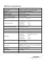
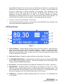
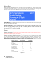
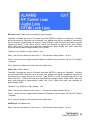
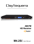
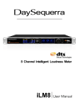
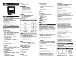
FM - HD Modulation Monitor M4FM-HD User Manual Welcome Thanks for purchasing the DaySequerra M4FM-HD FM Modulation Monitor. We design and build all of our DaySequerra products to be completely reliable and easy to use, so you can concentrate on producing great sounding broadcasts, not struggling with complicated equipment or difficult to use product manuals. While the M4FM-HD has been designed to be straightforward to use, we do suggest that you spend a few minutes familiarizing yourself with the features and operational functions that are contained in this manual. DaySequerra has been building broadcast quality products since 1989. The technology developed for the M4FM-HD, and all of our products, has evolved through a process of user feedback, extensive listening, field-testing and careful refinement. In the event that you encounter any technical or operational difficulties with this or any DaySequerra product, please feel free to contact us at 856-719-9900. Our office hours are from 9 to 5 ET, Monday through Friday. Or you can email your questions to: [email protected]. Also, please remember to visit our website www.daysequerra.com for warranty registration and the latest DaySequerra product information. We have worked hard to ensure that your DaySequerra M4FM-HD HD Radio Receiver will reliably serve as a flawless link between the transmitter and your monitoring facility, or as the primary broadcast reference source in your studio. We sincerely hope our products help you achieve a new level of excellence in your work! David V. Day and the DaySequerra Team 2 M4FM-HD User Manual Table of Contents Important Safety Information 4 Service Information 4 Introduction 5 M4FM-HD Key Features 6 M4FM-HD Technical Specifications 7 Unpacking and Installing 8 Operating Description - Controls and Indicators 9 Front Panel 9 Rear Panel 10 LCD Display 11 Modulation Measurements 12 System Menu 14 WebServer 20 Restore Factory Settings 26 Three Year Warranty 28 M4FM-HD – Features • Analog FM plus HD RadioTM – Complete monitoring of HD Radio FM broadcasts including FM multicast channels HD-2 through HD-8: userselectable tuning steps and analog FM 50/75 µSec de-emphasis. • Frequency-Agile RF Input – Synthesized FM preselector provides -50 dB quieting sensitivity < 30 dBf (-90 dBm) • Built-in RF Attenuator – 30 dB for wide RF input range of <0.5 vRMS to 7 vRMS • Worldwide Capable – Complete with user-selectable 100 or 200 kHz tuning steps and 50 or 75 µSec de-emphasis • Simultaneous Modulation Measurements – Total, pilot, L, R, L+R and L-R, and all Composite-SCA level measurements with better than 1.0% accuracy • Superb Audio Performance – +4 dBm @ 100% modulation with SNR > 75 dB and THD < 0.1%; full-time AES-3 digital audio output as well as a highperformance headphone output with greater than 1W into 8-ohm • Email Alerts and Rear Panel Alarm Tallies – For loss of Audio, Carrier and RDS/RBDS; remote reset via rear panel GPI All rights reserved DaySequerra Corp. Copyright 2009. All logos and trademark used herein are the property of their respective owners. Specifications subject to change. M4FM-HD M4FM-HD User Manual 3 Important Safety Information • • • • • • • • • • Indoor use only. Not for use in wet or damp environments. Maximum Relative Humidity: <80% Class I Equipment (grounded type) Electrical rating: 100-120/220-240V~50-60Hz 18W Fuse Rating: 2A 250V 20MM AC Mains supply voltage fluctuations are not to exceed +10% of the nominal voltage Operations temperature range -40°C to 70°C Maximum altitude: 3000m (9843ft) Equipment suitable for continuous operation Weight: 5.4kg (12lbs) equipment only; 8.2kg (18lbs) shipping Important Note: Please connect your M4FM-HD to an uninterruptible power supply (UPS) to provide other protection against power surges and brownouts. Service Information The DaySequerra M4FM-HD contains no user serviceable components inside the unit. Please contact DaySequerra for repair and upgrade information. In the event that your unit needs to be returned to the factory, contact us for a return authorization number. The monitor ID and firmware version is momentarily displayed at start-up for your convenience. Please visit www.daysequerra.com and register your new M4FM-HD so we can keep you informed of the latest hardware and software updates. 4 M4FM-HD User Manual Introduction DaySequerra’s M4FM-HD is the most powerful and cost-effective FM analog radio modulation monitor available today. Using a state-of-the-art Texas Instruments® DSP running at 350 MHz, all of the M4FMHD processing takes place in the digital domain. The M4FM-HD’s Texas Instruments® DSP provides superb analog audio performance (SNR > 75 dB and THD < 0.1%) as well as simultaneous total, pilot, L, R, L+R and L-R, and all Composite-SCA modulation level measurements with better than 1.0% accuracy. The M4FM-HD also provides decoded RDS/RBDS data. In addition to its accuracy and features, the M4FM-HD gives you audiophile grade Class-A biased audio outputs at +4 dBm on XLR connectors, so you can monitor and adjust your processing. In addition to L and R analog outputs, the M4FM-HD has a full-time AES-3 digital audio output, so you can feed your AES monitoring chain, and a high-performance headphone output with greater than 1W into 8-ohm for an uncompromised, convenient audio monitor. The M4FM-HD rear panel has an FM composite output, as well as a GPIO port that provides optoisolated reset input and relay-contact closure alarm outputs for loss of audio, carrier and RBDS. You can control and monitor the M4FM-HD from anywhere in your plant via the M4FM-HD’s integrated webserver, which is fully compatible with most web browsers and operating systems. The M4FM-HD’s Remote Dashboard provides complete remote control monitoring, 50 station scanning, logging and alarm status; it delivers simultaneous total, pilot, L, R, L+R and L-R, all MPX-SCA modulation level measurements and decoded RDS/RBDS data. The M4FM-HD will send alerts to your phone; and you can reset the M4FM-HD remotely as well. Your M4FM-HD is HD Radio ReadyTM meaning it can be fully upgraded at any time to provide complete HD Radio® capability. With our Factory-Direct Upgrade program, you can be sure that your investment in a DaySequerra M4FM-HD will continue to pay off well into the future. Please read this manual thoroughly before operating your M4FM-HD. M4FM-HD User Manual 5 M4FM-HD Key Features • Analog FM plus HD RadioTM – Complete monitoring of HD Radio FM broadcasts including FM multicast channels HD-2 through HD-8: user-selectable tuning steps and analog FM 50/75 µSec de-emphasis. • Bright LCD front panel display of Station, presets, RBDS with network and alarm conditions • Frequency-Agile RF Input – Synthesized FM preselector provides -50 dB quieting sensitivity < 30 dBf (-90 dBm) • Built-in RF Attenuator – 30 dB for wide RF input range of <0.5 vRMS to 7 vRMS • Worldwide Capable – Complete with user-selectable 100 or 200 kHz tuning steps and 50 or 75 µSec de-emphasis • Simultaneous Modulation Measurements – Total, pilot, L, R, L+R and L-R, and all Composite-SCA level measurements with better than 1.0% accuracy • Superb Audio Performance – +4 dBm @ 100% modulation with SNR > 75 dB and THD < 0.1%; full-time AES-3 digital audio output as well as a high-performance headphone output with greater than 1W into 8-ohm • Email Alerts and Rear Panel Alarm Tallies – For loss of Audio, Carrier and RDS/RBDS; remote reset via rear panel GPI • Remote Dashboard providing total remote control, display and remote reset from any browser including • 25 Webserver and 50 tuner presets with RBDS, network and alarm conditions • Audio level, digital audio quality and carrier quality indications • Complete remote firmware upgrade – tolerant of high-latency networks • FRONT PANEL ALARM LED – Indicates active alarm condition • PROGRAMMABLE STATUS ALARMS – alarm outputs for loss of audio program, carrier, pilot and RBDS as well as audio peak, all with programmable settings for level and duration 6 • High performance Headphone Monitor delivering greater than 1W into 8-ohm • Webserver compatible with any browser on your Ethernet network • Alarms can be emailed to your phone • Remote reset via WebServer • Use your Wireless Router for remote control using your Android® or iPhone® mobile device M4FM-HD User Manual M4FM-HD Technical Specifications Frequency Range FM: 87.5 MHz to 107.9 MHz in 100 or 200 KHz increments RF Input Range 0.5 vRMS to 7 vRMS on 75-ohm F-type connector Sensitivity < 30 dBf (-90 dBm) for -50 dB Quieting Modulation Frequency 30 Hz – 100 KHz Frequency Deviation ±75 KHz for 100% Modulation Frequency Deviation Indication 0 to 150% Deviation Frequency Deviation Indication Accuracy ±1.0% @ 0% to 150% Deviation Composite Signal Output Frequency Response < ± 0.25 dB THD (IEEE 185) < 0.1% IMD (SMPTE) < 0.1% SNR (IEEE 185) < 75 dB Channel Separation (L/R and R/L) > 45 dB, 30 Hz to 15 KHz Crosstalk (L+R) to (L-R) to (L+R) > 45 dB, 30 Hz to 15 KHz Pilot Carrier Measurement <± 0.50% @ 0% to 15% Injection Level Accuracy at all Modulation Levels <±1.0% @ 0% to 100% Modulation Audio Output Frequency Response < ± 0.25 dB De-Emphasis User Selected 50 or 75 µS THD (IEEE 185) < 0.1% IMD (SMPTE) < 0.1% SNR (IEEE 185) > 75 dB Power 40 W, Auto-sensing 90-264 VAC, 50/60 Hz Environmental Operating Temperature: +41 to +105 F (+5 to +40 C) Storage Temperature: -13 to +140 F (-25 to +60 C) Relative Humidity: Maximum 85%, non-condensing Dimensions 17.3” W x 1.7” H x 16.875” D Shipping Weight 12 lbs. (5.4 kg) Warranty Three years, limited parts and labor M4FM-HD User Manual 7 Unpacking and Installing the M4FM-HD Immediately upon receiving your M4FM-HD, please make a careful inspection for any shipping damage. If damage is found or suspected, please notify the carrier at once and then contact your dealer. The DaySequerra M4FM-HD is shipped in one carton, which contains: the M4FM-HD unit, and an AC power cable. We strongly encourage you to save the shipping carton and shipping materials supplied with your M4FM-HD. They are specially designed to properly protect your M4FM-HD, and in the event that you need to return it for service, only these OEM shipping materials can ensure its safe return to our factory. We provide a limited 3-year warranty on all of our products, but if you don’t register your unit, it’s hard for us to contact you when software updates become available. So please take a few minutes to complete the warranty registration form on our web site, www.daysequerra.com. Thank you! Rack Mount Installation. The M4FM-HD chassis has four rack mounting holes in its chassis and has been designed to fit in a 19” standard 1RU space. Plastic ‘finishing’ washers are recommended to protect the painted finish around the mounting holes. Power Connection. The AC power cable supplied with the M4FM-HD must be connected from the M4FM-HD’s IEC320 power entry module to an AC mains outlet with a functional earth ground connection. The M4FM-HD has been set at the factory to operate at 120VAC unless otherwise specified on the shipping carton. The M4FM-HD export version is configured for 240VAC operation. Please connect your M4FM-HD to an uninterruptible power supply (UPS) to protect against power surges and brownouts. Antenna Input Connections. Separate 75ohm F-type connector is provided on the M4FM-HD rear panel for dedicated AM and FM antennas Audio Output Connections. Analog audio left and right outputs are on rear-panel XLR connectors with pin 1 GND, pin 2 + and pin 3 -. The digital audio output is transformer-isolated in S/PDIF format on a rear-panel XLR connector with pin 1 GND, pin 2 XFMR and pin 3 XFMR. The M4FM-HD digital audio output is 5.1 surround capable. FM Composite Output has a Frequency Response <+/- 0.25dB, Total Harmonic Distortion (IEEE 185) <0.1%, IMD (SMPTE) <0.1%, SNR (IEEE 185) >75 dB Ethernet Connection - The M4FM-HD Ethernet Port offers the use of DaySequerra’s Webserver by connecting the M4FM-HD to any networked computer with Internet access. The use of crossover cables can be used in areas where a network connection is not possible. More information on the Webserver can be found at the end of this manual. The Ethernet port with the aid of the webserver will keep the M4FM-HD up to date on all Firmware upgrades by checking, downloading and installing with the click of the ‘Check Firmware’ button on the webserver. (An internet connection must me available for ‘Firmware Upgrade. to work. UPON RECEIVING THE UNIT IT IS ENCOURAGED TO ‘CHECK FIRMWARE’ FROM THE WEBSERVER TO BE SURE YOUR M4FM-HD IS USING THE MOST RECENT FIRMWARE AVAILABLE. 8 M4FM-HD User Manual Navigation The M4FM-HD employs a 3-button user interface. From the start ‘HomeScreen’ press the center button once. An arrow will appear next to the frequency. Use the UP/DN arrow button to toggle the Arrow on the LCD around the different fields on the HomeScreen. Press the Center button to select a field to change. The arrow will start to flash indicating that the UP/DN arrows are available to change the value of the field. Press the Center button to save and exit. To access the SYSTEM menu press and hold the center button for 3 seconds. M4FM-HD Operating Description - Controls and Indicators Front Panel Figure 1. Status • Alarms – Bi-colored LED: Green indicates that an alarm is set. Red LED illuminates when an alarm is active. Red will flash every second when an alarm conditions are met until either the user disables the alarm or the conditions move outside of the set parameters. • HD Locked – Blue LED illuminates when tuner has acquired OFDM (orthogonal frequency division multiplexing) portion of an HD Radium signal and digital carrier S/N > 58dB/Hz, thereby permitting HD Radium digital audio to be valid. HD is displayed in upper right hand corner of VFD when tuner has acquired OFDM portion of an HD Radium signal. • Multicast – Blue LED illuminates when tuner has acquired OFDM of an RadioTM signal and there is at least one multicast signal present. • RF Level – Bi-colored LED: Green indicates strong RF > 40 dB. Red indicates weak RF < 40 dB. • Up Arrow – Momentary push UP from the Homescreen will enter the Headphone volume menu. Both arrows are used to increase and decrease the volume. From selection mode Press ENTER again to change a value in any a field indicating a blinking arrow ready. Use the UP and DOWN arrows to navigate/toggle through the available choices or range. UP Arrow button tunes the frequency up one increment while tuning to a new station, when held for three seconds it tunes faster at 1.5x speed. UP selects next stored preset station in PRESETS mode (no faster mode, one push per preset). Selects next item in other menus and is used for other functions as described herein. Holding the UP arrow while powering the unit on will restore factory settings. M4FM-HD User Manual 9 • Down Arrow – Momentary push DOWN from the Homescreen will enter the Headphone volume menu. Both arrows are used to increase and decrease the volume. From selection mode Press ENTER again to change a value in any a field indicating a blinking arrow ready. Use the UP and DOWN arrows to navigate/toggle through the available choices or range. DOWN Arrow button tunes the frequency down one increment while tuning to a new station, when held for three seconds it tunes faster at 1.5x speed. Down selects next stored preset station in PRESETS mode (no faster mode, one push per preset). Selects next item in other menus and is used for other functions as described herein. • Center Button – Used to enter SELECTION MODE and to confirm and save that selection; Press and hold for 3 seconds to enter SYSTEM MENU. Press and hold for 3 seconds to exit SYSTEM MENU. • Reset Button – Using a paper clip press the reset button hidden behind the front panel to the right of the center button to power cycle the unit while holding all presets and other settings in memory. • Headphones - Accepts any headphone or monitor that has a 3.5mm stereo mini-jack connection. Volume control is software based, from the home screen by pressing either arrow button UP/DN to enter the volume control. Press ENTER to exit and save the desired volume. Rear Panel Figure 2. • RF Input F-Type 75 ohm - FM: -55 dBm Nominal: -20 dBm Maximum • Analog Audio Outputs – Left/Right Balanced XLR - +4 dBm into 600 ohm at 100% modulation • Digital Audio Output – AES-3 Professional, 110Ω transformer-isolated on XLR connector; 0 dBFS <0.005% THD+N • FM Composite Output – Frequency Response <+/- 0.25dB, Total Harmonic Distortion (IEEE 185) <0.1%, IMD (SMPTE) <0.1%, SNR (IEEE 185) < 75 dB for decoding • GPI – The PLM provides six dry, floating relays with outputs on a rear panel mounted DB15 connector to report selected alarm conditions, including loss of RF carrier, program audio, Over Modulation, HD Lock and Multicast Loss. See the PIN out chart for details on page 14 under ‘ALARMS’. 10 M4FM-HD User Manual • The M4FM-HD Ethernet Port offers the use of DaySequerra’s Webserver by connecting the M4FM-HD to any networked computer with Internet access. The use of crossover cables can be used in areas where a network connection is not possible. More information on the Webserver can be found at the end of this manual. The Ethernet port with the aid of the webserver will keep the M4FM-HD up to date on all Firmware upgrades by checking, downloading and installing with the click of the ‘Check Firmware’ button on the webserver. (A network Internet connection must be available to successfully upgrade the firmware.) • AC Power - Auto-sensing 85-264VAC, 47-63Hz input. • The Power (Rocker) switch is located on the rear panel of the M4FM-HD; when switched on the unit model number will be displayed on the LCD. LCD HomeScreen 4 5 1 6 2 7 3 8 Figure 3. 1. Tuner Frequency – Selects manual FM tuning with UP and DN controls. Press the center button once to bring up the selection arrow and navigate to position 1 as described above. (Note the arrow will timeout after 15 seconds of inactivity). Press the center button again (flashing arrow) indicating the station is ready to be tuned. Press the center button again to exit or wait 15 seconds for it to timeout. 2. Station Call Letters – Displays the station call letters with the Band. (Read-only) 3. IP / RDS/RBDS/PAD/SIS Data – Toggles between a static IP address and decoded RDS/RBDS data for display on the bottom of the LCD. This field also displays active alarm details, which override IP and RDS/RBDS/PAD/SIS data. 4. RF Indicator – Horizontal strength bars are displayed indicating the RF strength. (Read-only) 5. BAND/PRESET – FM Band indicator; 50 FM stations are available to be stored. To store a station as a preset hold the center button for 3 seconds while tuned to the desired station. The next available preset will start flashing in place of FM. Example F-01. While flashing the arrow buttons can navigate to any of the already saved preset to be overwritten. 6. ST/Multicast – Displays the available multicast stations HD 1 thru HD 8. ST is displayed if HD is not available M4FM-HD User Manual 11 7. Tuner Mode – Switch between Auto, Forced Digital, Forced Analog, and Mono. By default the tuner is set to AUTO. Auto Mode – The tuner will attempt to lock on an HD Radio signal if available. If HD is unavailable the tuner will fall back to Analog. Forced Mono – Forces the tuner to Mono from Stereo. Forced Analog – Forces the tuner to Analog from Digital. Forced Digital – Forces the tuner to digital. If the digital signal is not strong enough the tuner will fall back to Analog. (Auto Digital-Force enabled in the system tab ensures the tuner will not fall back to Analog if the signal is on the edge of HD and Analog). 8. Modulation - enters a submenu displaying measurements for Audio, Demodulation, and Subcarriers. More information on Modulation on the next page. Modulation Measurements A series of read-only submenus displaying audio, demodulation and subcarrier measurements. To exit to the previous menu enter selection mode and toggle the arrow up to EXIT and press the CENTER button to revert back to the home screen. (Graphical representations of these are available in the meters of the webserver) Figure 4. Audio Figure 5. 12 M4FM-HD User Manual Integer values for Left, Right, Left + Right and Left – Right are displayed in dB. This is a read-only submenu. Figure 6. Demodulation Figure 7. Integer values for Positive, Negative and Total Positive and Negative are displayed in %. This is a read-only submenu. Subcarriers Figure 8. Integer values for Pilot, 57 kHz, 67 kHz, and 92 kHz are displayed in %. This is a read-only submenu. M4FM-HD User Manual 13 System Menu Press and hold the CENTER button for 3 seconds to enter the SYSTEM menu. Use the arrow buttons to navigate to the desired submenu. To exit to the previous menu enter selection mode and toggle the arrow up to EXIT and press the CENTER button to revert back to the previous screen. Figure 9. Audio Muting - The M4FM-HD’s audio output can be set to automatically mute for received signals with signal strength less than 45dBf. Forcing A-D Split – using headphones this feature puts the Digital signal in the left ear and the Analog in the right ear. Enabling SPLIT mode will disable all tuning until SPLIT mode is disabled. Alarms Program Loss Monitor – Enabling any alarm will disable tuning, presets and band selection from the WebServer and M4FM-HD box User interface. Program Loss Monitor (PLM) Connections – The PLM provides six dry, floating relays with outputs on a rear panel mounted DB15 connector to report selected alarm conditions, including loss of RF carrier, audio loss, OFDM Lock Loss, HD Lock Loss, Multicast Loss, and Over Modulation. Optoisolated inputs will be triggered by a voltage of 5VDC. The GPIO Alarm output relays are Normally Open and will close when an alarm is active. See figure 10 for the DB15 pin-outs: Alarm Loss of: No Contact Audio 5 10 RF Carrier 4 9 OFDM Lock Loss 3 8 HD Lock Loss 2 7 Multicast Loss 1 6 Over Modulation 11 12 Reset 14 15 Pin 13 is not used Figure 10. 14 Common M4FM-HD User Manual Figure 11. RF Carrier Loss - Alarm based on analog RF signal strength Threshold: Navigate the arrow to Threshold and press ENTER to change the Threshold. A blinking arrow will indicate the Threshold can be changed. Low, Medium and High are available to choose from. Use the arrows to toggle through the choices. Press ENTER to make a selection and return to the RF Carrier Loss menu. “LOW” option sets RF carrier loss threshold for approximately 10µV (25dBf); “MED” option sets RF carrier loss threshold for approximately 100µV (45dBf); and “HIGH” option sets RF carrier loss threshold for approximately 3KµV (75dBf). Threshold: Low, Medium or High. (Default – low) Delay: Use the arrow buttons to select from 1 – 300 seconds of delay (default – 15 sec) Status: Use the arrows to toggle between Enabled or disabled to turn the alarm ‘ON’ and ‘OFF (default – disabled) Save: Saves all conditions and exits back to the Alarm menu. Audio Loss - Silence Detect Threshold: Navigate the arrow to Threshold and press ENTER to change the Threshold. A blinking arrow will indicate the Threshold can be changed. Low, Medium and High are available to choose from. Use the arrows to toggle through the choices. Press ENTER to make a selection and return to the Audio Loss menu. “LOW” option sets audio loss threshold for approximately -60dB; “MED” option sets audio loss threshold for approximately -40dB; and “HIGH” option sets audio loss threshold for approximately -20dB. Threshold: Low, Medium or High. (Default – low) Delay: Use the arrow buttons to select from 1 – 300 seconds of delay (default 15 sec) Status: Use the arrows to toggle between Enabled or disabled to turn the alarm ‘ON’ and ‘OFF’ (default – disabled) Save: Saves all conditions and exits back to the Alarm menu. OFDM Lock - Side Bands Lost Delay: Use the arrow buttons to select from 1 – 300 seconds of delay (default – 15 sec) M4FM-HD User Manual 15 Status: Use the arrows to toggle between Enabled or disabled to turn the alarm ‘ON’ and ‘OFF’ (default – disabled) Save: Saves all conditions and exits back to the Alarm menu. HD Lock - HD signal lost Delay: Use the arrow buttons to select from 1 – 300 seconds of delay (default – 15 sec) Status: Use the arrows to toggle between Enabled or disabled to turn the alarm ‘ON’ and ‘OFF’ (default – disabled) Save: Saves all conditions and exits back to the Alarm menu. Multicast – HD-1 thru HD-8 unavailable Delay: Use the arrow buttons to select from 1 – 300 seconds of delay (default – 15 sec) Status: Use the arrows to toggle between Enabled or disabled to turn the alarm ‘ON’ and ‘OFF’ (default – disabled) Save: Saves all conditions and exits back to the Alarm menu. Over Modulation - The Carrier Over Modulation alarm is factory set to alarm for a level over 105% by default. It can be manually set within the range of 100% - 125% in 1% increments. Modulation Level: Use arrow buttons to select between 100% - 125% modulation in 1% increments Delay: Use the arrow buttons to select from 1 – 300 seconds of delay (default – 15 sec) Status: Use the arrows to toggle between Enabled or disabled to turn the alarm ‘ON’ and ‘OFF’ (default – disabled) Save: Saves all conditions and exits back to the Alarm menu. Relay Output Customizes a specific alarm to each of the six relay outputs on the DB-15. See figure 10. for the DB-15 pin-out • Output 1 – RF Carrier loss, Audio Loss, OFDM Lock Loss, HD Lock Loss, Multicast Loss, Over Modulation, Empty Default: RF Carrier Loss • Output 2 – RF Carrier loss, Audio Loss, OFDM Lock Loss, HD Lock Loss, Multicast Loss, Over Modulation, Empty Default: Audio Loss • Output 3 – RF Carrier loss, Audio Loss, OFDM Lock Loss, HD Lock Loss, Multicast Loss, Over Modulation, Empty Default: OFDM Lock Loss • Output 4 – RF Carrier loss, Audio Loss, OFDM Lock Loss, HD Lock Loss, Multicast Loss, Over Modulation, Empty Default: HD Lock Loss 16 M4FM-HD User Manual • Output 5 – RF Carrier loss, Audio Loss, OFDM Lock Loss, HD Lock Loss, Multicast Loss, Over Modulation, Empty Default: Multicast Loss • Output 6 – RF Carrier loss, Audio Loss, OFDM Lock Loss, HD Lock Loss, Multicast Loss, Over Modulation, Empty Default: Over Modulation Toggle the arrow to the top right of the LCD and select EXIT to revert back to the previous page. Audible Alarm Buzzer “ON” or “OFF” option using UP and DN switches to toggle the setting. Select “ON” for audible alarm to beep during any active alarm condition and continue with alarm configuration menu; select “OFF” for audible alarm to be silent during any active alarm condition. Press ENTER to save and exit to the previous Alarm menu FM De-Emphasis Switch between 75µsec and 50µsec. M4FM-HD is set to 75µsec by default. Press ENTER after making a selection to save and EXIT to the previous menu. (Figure 12) Figure 12. Region Figure 13. M4FM-HD supports 100 KHz or 200 KHz tune spacing for US and Euro. (Illustrated in figure 13.) The factory default is set to US, 200 KHz. Press ENTER after making a selection to save and EXIT to the previous menu M4FM-HD User Manual 17 RF Loss Pad -30 dB of attenuation is applied during startup by default unless this feature is disabled. Remotely this feature is available with the ‘Other Settings’ box in the System Menu of the webserver. Enable or Disable. (Default: Enabled) Select to exit to the previous menu. Diagnostics A Read-Only menu displaying the SNR (Signal to Noise Ratio) in dB. The Date with a running 12-hour AM/PM clock. Toggle Exit with the arrow and press ENTER to exit to the previous menu. Figure 14. Network A Read-Only menu that displays the current status of DHCP, the static IP address, Subnet, Gateway and MAC address. Toggle Exit with the arrow and press ENTER to exit to the previous menu. More NETWORK details can be viewed Figure 15. DHCP is set to ‘ON’ by default. Disabling DHCP allows the users to manually enter an IP, Subnet and Gateway. Exiting this menu will save and reset the M4FM-HD if a change has been made to DHCP. The new manual IP address will be displayed on the LCD homescreen Enter selection mode and toggle the arrow to IP, Subnet or Gateway and press the ENTER button once. The first field (3 digits) will start to flash. Use the arrow buttons to change up or down within the allowed range. Press ENTER after each field to save and move to the next field. Pressing ENTER 18 M4FM-HD User Manual after the last field saves all changes. The arrow will stop flashing indicating it is in selection mode. Toggle Exit with the arrow and press ENTER to exit to the previous menu. Once a change has been made the unit will reset and automatically restart. About A Read-Only menu displaying the HDRadio, DSP, and Firmware version. The selection mode arrow is defaulted to the top right corner of the menu. To Exit press ENTER. More ABOUT details can be viewed in the Settings tab of the WebServer. Figure 16. Exit Located at the top right corner of the Alarm menu is used to exit back to the previous SYSTEM menu. From Alarms menu press the UP arrow button until the arrow is to the right of EXIT on the LCD then press ENTER to exit. M4FM-HD User Manual 19 WebServer Provides full access to the M4FM-HD remotely via web browser. A network connection or crossover cable is required for this feature. Crossover cables may be used when a Network connection is not available. Power ON the M4FM-HD and open a web browser. Type the IP address of the M4FM-HD in the URL to open the WebServer. Five tabs are displayed at the top of the WebServer window – M4FM-HD, Meters, Alarms, Network, and System Tuner – The main tab that controls Frequency Tuning in a large font, displays station call letters and ST indicator when the tuner is locked onto a Stereo signal and 25 FM Presets with the current Alarm Status of the M4FM-HD. Meters – Displays integer values for the Subcarriers (Pilot, 57 KHz, 67 KHz, and 92 KHz); Bargraph meters for Audio and Demodulation levels. Alarms – Enables and disables each of the 6 alarms (RF Carrier Loss, Audio Loss, OFDM Lock Loss, HD Lock Loss, MC Loss, and Over Modulation. A relay output pull down menu is available to set each of the six alarms for external monitoring via DB-15. Network – Displays and sets all network settings, Private FTP, and Email Notifications for alarms. System – Provides remote configuration of all of the Alarm features, Email and Network settings. About window displays the M4FM-HD Serial and Firmware number and Box ID. All Firmware Upgrades are performed by clicking the ‘Check for Update’ box. A private FTP site may be setup to perform upgrades. Please contact DaySequerra if you wish to perform upgrades using Private FTP so you are notified when updates become available. Remotely resetting the M4FM-HD can be accomplished by clicking on the Reset button at the bottom of this tab. The most recent M4FM-HD user manual is also available for download by checking its box. 20 M4FM-HD User Manual Tuner Tab 4 5 6 1 7 2 8 3 9 Figure 17. 1. Tuner Frequency - The tuned frequency is displayed in a large font here. Tuning buttons tunes the frequency Up and Down within the range of 87.5 MHz to 107.9 MHz in 100 or 200 KHz increments. Holding the button for more than 3 seconds will increase the speed by a factor of 2. 2. Multicast - Displays multicast HD-1 thru HD-8 when available highlighted in bold. Selecting highlights the text in orange. 3. Artist Experience – Displays album art when available 4. RF Level and SNR – Displays the amount of RF strength from the tuned frequency; SNR – Displays READ-ONLY signal to noise ratio express in dB 5. Webserver Status - READ-ONLY message field that displays the active status of the web browser 6. Alarm Status window – Indicator displaying any active alarms in a bold red font. 7. Tuner Mode – sets: • AUTO – tuner will automatically acquire HD when available. If HD is not available the tuner will fall back to Analog • FORCED MONO – forces the tuner to Mono • FORCED ANALOG – forces the tuner back to Analog from Digital M4FM-HD User Manual 21 • FORCED DIGITAL – forces the tuner into Digital. If Digital is not available or the signal is too weak the tuner will fall back to Analog. *Enabling Digital Auto Force in the ‘Other Settings’ section of the webservers SYSTEM tab will force the tuner into Digital and prevent it from falling back to Analog. If Analog is unavailable the tuner will mute. 8. Preset selection - 25 slots for FM stations are available to be stored. Holding a preset buttons for more than 3 seconds will save the currently tuned station in that slot. Hold an already saved preset for more than 3 seconds will overwrite and save the currently tuned station in that slot. Unavailable when Alarms are enabled. 9. RDS/RBDS & PAD/SIS data window – RDS/RBDS data will scroll when available. RBDS scrolls the PI (Call Letters), PS (Program Service), PTY (Program Type) and RT (Radio Text). Any active alarm condition will override this data. PAD/SIS data will scroll when available during HD Lock. Meters Tab 1 2 3 Figure 18. 1. Audio Measurements (Bargraph) – displaying Left, Right, Left + Right and Left – Right in dB. Integer values of these measurements are available in the M4FM-HD’s meters submenu. 22 M4FM-HD User Manual 2. Carrier Measurements (Bargraph) – displaying Positive, Negative and Total Positive + Negative in percent. Integer values of these measurements are available in the M4FM-HD’s meters submenu. 3. Subcarrier Measurements (Integer) – displaying Pilot, 57 KHz, 67 KHz, and 92 KHz levels in percent Alarms Tab 2. 3. 1. Figure 19. 1. Alarm configurations – sets the individual conditions for each of the 6 alarms. *Slide the Enable switch to the right to enable an alarm. The M4FM-HD box user interface will display the exact state of the alarm under ‘Status’ Enable = Alarm ON, Disable = Alarm OFF. Enabling any one alarm will disable tuning. Disable ‘Alarms Lock Tuning’ from the ‘Other Settings’ section of the webservers SYSTEM tab to turn this feature off. By default the Alarms Lock Tuning is enabled. 2. Alarm Status – READ-ONLY window that displays the real-time status for each of the set alarms. M4FM-HD User Manual 23 3. Program Loss Relay Outputs – configures the M4FM-HD for alerts externally via GPIO when Alarm conditions become active. Each relay can be set to any of the 6 alarms or empty. See figure 10 on page 14 for the DB-15 pinout. Network Tab 1. 3. 2. Figure 20. 1. Network Settings – Enables and disables DHCP. Enabling DHCP allows the DHCP router to chose an IP address for the M4FM-HD and auto-populate the subnet and gateway. The tuners MAC is READ-ONLY and cannot be changed. Disabling DHCP allows the user to manually enter the IP address, Subnet, and Gateway. Select SAVE to store the settings. The settings are not set until saved. 2. Private FTP Settings – Enables and disables the use of a private FTP site to store firmware updates. Enabling this feature will direct the M4FM-HD to the host IP provided by the user when checking for firmware updates. Select SAVE after entering the Host IP, User name, Password, and Port #. The settings are not set until saved. 3. Email Notifications – Enables and disables emails sent out when alarm conditions are active. To enable enter SMTP IP, Port #, User name, Password, Sender email address, and receiver email address. Select SAVE to save the settings and activate. Settings are not set until saved. Select TEST to verify that the settings have been entered properly and emails are sent/received. *Password is case sensitive alphanumeric. No spaces or symbols may be used. SSL encrypted logins are currently unavailable – coming soon in a future firmware release. 24 M4FM-HD User Manual System Tab 1. 4. 2. 3. Figure 21. 1. Network Time – M4FM-HD will automatically acquire the network time from the host server. Set the Time Zone and Daylight Savings for your region. 2. Misc. Settings – Sets many of the tuners basic features. a. Audio muting - The M4FM-HD’s audio output can be set to automatically mute for received signals with signal strength less than 45dBf. b. RF loss pad - Attenuates the amount of RF to the tuner in high RF areas by -30 dB c. De-Emphasis - Switch between 75µsec and 50µsec. M4FM-HD is set to 75µsec by default. Press ENTER after making a selection to save and EXIT to the previous menu. d. Region – Sets the tune spacing to 100 kHz for Euro or 200 kHz for US. Default setting is set to US. e. Alarms lock tuning – Enables and disable front panel and webserver tuning while alarms are set. f. Digital auto-force – Sets the tuner to always force digital and never fall back to Analog when a digital signal is below the threshold for HD Lock. The tuner will mute if Digital is M4FM-HD User Manual 25 not available. This feature is independent of the Tuner Mode pull down menu within the main tuner tab. g. Auto backlight off – Enabling this feature will turn the LCD backlight off after 120 seconds. Waking the tuner up by tuning from the webserver or pressing any of the 3 buttons on front panel will turn the LCD back on and reset the 120 second timeout again. Disabling will keep the LCD backlight illuminated full time. 3. Actions a. Check for update - Check for Update’ when selected will search for a more recent version of firmware if available. A pop-up window will tell the user if the Firmware is current or an update is available. If an update is available the firmware will be automatically downloaded. Once the download is complete the M4FM-HD will automatically power cycle to complete the update. Refreshing the web browser is recommended after an update. The new Firmware version, Build number, and build date will be displayed in the ‘ABOUT’ window of the Settings tab and also in the About menu of the M4FM-HD Box User Interface. At this time ‘Firmware Upgrade’ does not automatically check for updates so it is recommended to manually check periodically. b. Local update – select to update locally. Contact DaySequerra to obtain a compiled .bin file to upload via the local update GUI. c. Downgrade firmware – Downloads the previous firmware version (1 iteration behind the current). The current and previous firmware versions are always available for download. d. Update DSP only - downloads and updates the most recent firmware version for the DSP without disturbing the system firmware. e. Reset Unit – Performs a soft reboot of the unit. This does not restore factory defaults. The last state of the machine will be returned. f. Download user manual – The most recent version of the M4FM-HD user manual in PDF format is available at all times by clicking ‘Download’. g. Lock front panel - Disables the front panel locking it out from changes by unwanted users. 4. About Read-only menu that displays the Box ID, Serial Number, Firmware Version, Build Number, and Build Date. Restore Factory Settings To restore your M4FM-HD unit back to the original factory settings hold the UP arrow button in for 3 seconds while applying power to the unit. Release the UP arrow button once the power is restored to the unit. The original factory default settings will then be restored. Warning: Restoring the tuner to the original factory defaults will erase all settings and presets and cannot be reversed. Copy any settings and presets before restoring the tuner. 26 M4FM-HD User Manual DaySequerra – Three Year Limited Warranty DaySequerra warrants this product to be free from defects in materials and workmanship to its original owner for three (3) years from the date of purchase. DaySequerra will repair or replace such product or part thereof that upon inspection by DaySequerra, is found to be defective in materials or workmanship. A Return Authorization Number must be obtained from DaySequerra in advance of return. Call DaySequerra at (856) 719-9900 to receive the number to display on the outside of your shipping carton. A written statement with the name, address, and daytime telephone number of the original owner, together with receipt from the original purchase, and a brief description of any claimed defects, must accompany all returns. Parts or product for which replacement is made shall become the property of DaySequerra. The customer shall be responsible for all costs of transportation and insurance to and from the DaySequerra factory, and all such costs will be prepaid. DaySequerra shall use reasonable efforts to repair or replace any product covered by this limited warranty within thirty days of receipt. In the event repair or replacement shall require more than thirty days, DaySequerra shall notify the customer accordingly. DaySequerra reserves the right to replace any product that has been discontinued from its product line with a new product of comparable value and function. This warranty shall be void in the event a covered product has been damaged, or failure is caused by or attributable to acts of God, abuse, accident, misuse, improper or abnormal usage, failure to follow instructions, improper installation or maintenance, alteration, or lightning, power fluctuations and other incidental or environmental conditions. Further, product malfunction or deterioration due to normal wear is not covered by this warranty. DAY SEQUERRA DISCLAIMS ANY WARRANTIES, EXPRESSED OR IMPLIED, WHETHER OF MERCHANTABILITY OR FITNESS FOR A PARTICULAR USE, EXCEPT AS EXPRESSLY SET FORTH HEREIN. THE SOLE OBLIGATION OF DAY SEQUERRA UNDER THIS LIMITED WARRANTY SHALL BE TO REPAIR OR REPLACE THE COVERED PRODUCT, IN ACCORDANCE WITH THE TERMS SET FORTH HEREIN. DAY SEQUERRA EXPRESSLY DISCLAIMS ANY LOST PROFITS, GENERAL, SPECIAL, INDIRECT OR CONSEQUENTIAL DAMAGES WHICH MAY RESULT FROM BREACH OF ANY WARRANTY, OR ARISING OUT OF THE USE OR INABILITY TO USE ANY DAY SEQUERRA PRODUCT. Some states do not allow the exclusion or limitation of incidental or consequential damages or limitation on how long an implied warranty lasts, so the above limitations and exclusions may not apply to you. This warranty gives you specific legal rights, and you may also have other rights that vary from state to state. DaySequerra reserves the right to modify or discontinue, without prior notice to you, any model or style product. If warranty problems arise, or if you need assistance in using your product contact: DaySequerra 154 Cooper Road, Building 902 West Berlin, NJ 08091 856-719-9900 (phone) 856-719-9903 (fax) For more information, please visit www.daysequerra.com or email us at [email protected]. M4FM-HD User Manual 27