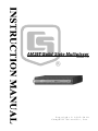
1
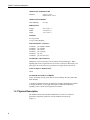
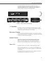
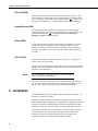
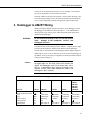
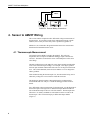
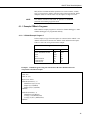
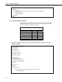
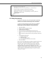
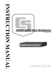
AM25T Solid State Multiplexer
Revision: 1/10
C o p y r i g h t © 1 9 9 5 - 2 0 1 0
C a m p b e l l S c i e n t i f i c , I n c .
Warranty and Assistance
The AM25T SOLID STATE MULTIPLEXER is warranted by CAMPBELL
SCIENTIFIC, INC. to be free from defects in materials and workmanship
under normal use and service for twelve (12) months from date of shipment
unless specified otherwise. Batteries have no warranty. CAMPBELL
SCIENTIFIC, INC.'s obligation under this warranty is limited to repairing or
replacing (at CAMPBELL SCIENTIFIC, INC.'s option) defective products.
The customer shall assume all costs of removing, reinstalling, and shipping
defective products to CAMPBELL SCIENTIFIC, INC. CAMPBELL
SCIENTIFIC, INC. will return such products by surface carrier prepaid. This
warranty shall not apply to any CAMPBELL SCIENTIFIC, INC. products
which have been subjected to modification, misuse, neglect, accidents of
nature, or shipping damage. This warranty is in lieu of all other warranties,
expressed or implied, including warranties of merchantability or fitness for a
particular purpose. CAMPBELL SCIENTIFIC, INC. is not liable for special,
indirect, incidental, or consequential damages.
Products may not be returned without prior authorization. The following
contact information is for US and International customers residing in countries
served by Campbell Scientific, Inc. directly. Affiliate companies handle
repairs for customers within their territories. Please visit
www.campbellsci.com to determine which Campbell Scientific company
serves your country.
To obtain a Returned Materials Authorization (RMA), contact CAMPBELL
SCIENTIFIC, INC., phone (435) 753-2342. After an applications engineer
determines the nature of the problem, an RMA number will be issued. Please
write this number clearly on the outside of the shipping container.
CAMPBELL SCIENTIFIC's shipping address is:
CAMPBELL SCIENTIFIC, INC.
RMA#_____
815 West 1800 North
Logan, Utah 84321-1784
For all returns, the customer must fill out a “Declaration of Hazardous Material
and Decontamination” form and comply with the requirements specified in it.
The form is available from our website at www.campbellsci.com/repair. A
completed form must be either emailed to [email protected] or faxed to
435-750-9579. Campbell Scientific will not process any returns until we
receive this form. If the form is not received within three days of product
receipt or is incomplete, the product will be returned to the customer at the
customer’s expense. Campbell Scientific reserves the right to refuse service on
products that were exposed to contaminants that may cause health or safety
concerns for our employees.
AM25T Solid State Multiplexer
Table of Contents
PDF viewers note: These page numbers refer to the printed version of this document. Use
the Adobe Acrobat® bookmarks tab for links to specific sections.
1. General .........................................................................1
1.1 AM25T Specifications..............................................................................1
1.2 Physical Description .................................................................................2
1.3 Operation ..................................................................................................3
2. Installation....................................................................4
3. Datalogger to AM25T Wiring.......................................5
4. Sensor to AM25T Wiring .............................................6
4.1 Thermocouple Measurement ....................................................................6
4.2 Differential Analog Measurements...........................................................7
4.3 Mixed Sensor Types .................................................................................7
5. General Measurement Considerations ......................8
6. Datalogger Programming............................................8
6.1 CRBasic Programming .............................................................................8
6.1.1 Example CRBasic Programs .........................................................11
6.1.1.1 CR1000 Example Program 1...............................................11
6.1.1.2 CR1000 Example Program 2...............................................12
6.2 Edlog Programming................................................................................13
6.2.1 Example CR10(X) Programs ........................................................14
6.2.2 Example CR23X Program ............................................................18
Appendices
A. Single-Ended Measurements ................................. A-1
A.1 Directions for Single-Ended Measurements ....................................... A-1
A.2 Indexing with Loops ........................................................................... A-5
B. Differences Between the AM25T, AM416, and
the AM32........................................................................ B-1
i
AM25T Solid State Multiplexer Table of Contents
Figures
1. AM25T Thermocouple Multiplexer........................................................... 3
2. External Battery Connections .................................................................... 6
3. Differential Measurement of Type T Thermocouple ................................. 7
4. Differential Voltage Measurement............................................................. 7
A-1. Single-Ended Measurement of a Type T Thermocouple ................... A-2
A-2. Single-Ended Measurement............................................................... A-5
Tables
3-1.
6-1.
6-2.
6-3.
Datalogger to AM25T Wiring ................................................................ 5
Wiring for CR1000 Example 1............................................................. 11
Wiring for CR1000 Example 2............................................................. 12
RTD Excitation Voltage and Measurement Range for AM25T
Multiplexers Prior to Serial Number 1839 ........................................ 14
6-4. Wiring for CR10(X) Examples............................................................. 14
6-5. Wiring for CR23X Example................................................................. 18
A-1. Values in Input Storage; Input Location Not Indexed ....................... A-5
A-2. Values in Input Storage; with Input Location Index and without
Step Loop Index Instruction ............................................................ A-6
A-3. Values in Input Storage; with Input Location Index and Step
Loop Index Instruction .................................................................... A-6
Program Examples
1. CR1000 Program Using One Instruction to Measure Both the
Reference Temperature and Thermocouples..................................... 11
2. CR1000 Program that Uses Separate AM25T Instructions to
Measure the PRT and Thermocouples .............................................. 12
3. CR10(X) Program for Measuring 25 Type T Thermocouples or
Voltage Sensors Using a Differential Instruction.............................. 14
4. CR10(X) Program for Measuring 25 Type T Thermocouples with
the Differential Thermocouple Instruction and Long Lead
Length Compensation on the RTD Measurement ............................. 16
5. CR23X Program for Measuring 25 Type T Thermocouples.................... 18
A-1. CR10 Program for Measuring 50 Type T Thermocouples or
Voltage Sensors Using a Single-Ended Instruction......................... A-2
A-2. 21X Program for Measuring 50 Type T Thermocouples or
Voltage Sensors Using Single-Ended Instruction .......................... A-3
A-3. Single-Ended Thermocouples, Input Location Not Indexed ............. A-6
A-4. Measuring Single-Ended Thermocouples with the Input
Location Indexed and no Step Loop Index ..................................... A-7
A-5. Measuring Single-Ended Thermocouples with the Input
Location Indexed and Step Loop Index ......................................... A-7
ii
AM25T Solid State Multiplexer
1. General
The AM25T Multiplexer increases the number of channels for measuring
thermocouples or voltage sensors with Campbell Scientific dataloggers. The
AM25T is positioned between the sensors and the datalogger. The datalogger
controls the AM25T's solid state relays, sequentially connecting each sensor to
the datalogger.
The AM25T is not suitable for resistive bridge measurements (high impedance
of the solid state relays) or multiplexing power (25 mA maximum switching
current).
A maximum of 25 thermocouples (differential voltage measurement) can be
multiplexed by an AM25T. Single-ended voltage measurements are not
recommended (Appendix A).
The AM25T must be used in a non-condensing environment. An enclosure is
required for field use. In applications where one or two multiplexers are
deployed in the field, the ENC12/14 can be used. The ENC16/18 can be used
to house several multiplexers at the same site.
1.1 AM25T Specifications
POWER
Unregulated 9.6 V to 16 V; 12 VDC Nominal
CURRENT DRAIN
Quiescent:
Active:
0.5 mA
1.0 mA (typical)
ENABLE
Inactive:
Active:
< 0.9 V
3.5 to 5.0 V (7 V max.)
CLOCK
The relays are advanced on the falling edge of the clock pulse (transition from
>3.5 V to <1.5 V; 7 V max.). The minimum clock pulse width is limited by
the datalogger.
Minimum ON time
Minimum OFF time
50 microseconds
60 microseconds
1
AM25T Solid State Multiplexer
OPERATING TEMPERATURE
Standard:
-40°C to +85°C
RTD accuracy ±0.4°C
OPERATING HUMIDITY
Noncondensing:
0 to 95%
DIMENSIONS
Length:
Width:
Depth:
23.6 cm (9.3”)
5.10 cm (2.0")
13.2 cm (5.2”)
WEIGHT
0.91 kg (2.0 lbs)
3.6 kg (8.0 lbs); Shipping
EXPANDABILITY (nominal)**
2 AM25Ts
4 AM25Ts
6 AM25Ts
4 AM25Ts
6 AM25Ts
7 AM25Ts
per CR800 or CR850
per CR1000
per CR23X
per CR10(X)
per 21X
per CR7 725 Card
MAXIMUM CABLE LENGTH
Multiplexers can be located up to 305 m (1000 ft) from the datalogger. When
lightning protection is required, do not exceed 152 m (500 ft) in cable length. The
spark gaps will not fire if the heavy ground wire is longer than 152 m (500 ft).
TYPICAL RELAY RESISTANCE
500 Ω
MAXIMUM SWITCHING CURRENT
25 mA; Switching currents greater than 25 mA will damage the relays and render
them unusable.
**Assumes sequential activation of multiplexers and that each datalogger channel
is uniquely dedicated. If your application requires additional multiplexing
capability, please consult CSI for application assistance.
1.2 Physical Description
The AM25T is housed in an anodized aluminum case with a cover that will
help reduce temperature gradients across the AM25T's terminal strips
(Figure 1).
2
AM25T Solid State Multiplexer
The terminal strips that run the length of the AM25T are for sensor
connections. All inputs are protected by spark gaps. All terminals accept
stripped and tinned lead wires up to 1.5 mm (0.059 inches) in diameter. A
strain-relief flange is located between the input terminals.
AM25T
LOGAN UTAH
+12
CLK RES EX AG
HI
LO
1H 1L
2H
2L
3H
3L
4H
13H 13L
14H 14L
15H 15L
5H
5L
AM25T
Logan, Utah
12H 12L
4L
16H 16L
17H 17L
18H 18L
19H 19L
SOLID STATE THERMOCOUPLE
MULTIPLEXER
MADE IN USA
6H
6L
7H
7L
8H
8L
9H
9L
10H 10L
S/N
SOLID STATE THERMOCOUPLE
MULTIPLEXER
1011
MADE IN USA
20H 20L
21H 21L
11H 11L
22H 22L
23H 23L
24H 24L
25H 25L
FIGURE 1. AM25T Thermocouple Multiplexer
1.3 Operation
The AM25T is connected to the datalogger with eight insulated wires and a
large ground wire. These wires are used to power and control the multiplexer,
and connect the common analog inputs to the datalogger.
Measurement Terminals
There are 25 differential channels on the AM25T. These channels are labeled
1H and 1L through 25H and 25L. The channels are sequentially connected and
reversed to the common channels HI and LO.
Excitation Terminal
This terminal is used to excite the reference temperature (RTD) on the
AM25T. The excitation line is protected from transients with a transorb.
(Earlier versions of the AM25T, prior to 1839, used a zener diode for
protection. The diode limited the negative excitation voltage to -400 mV).
Power (12 V)
The AM25T requires a 9.6 to 16 VDC (12 VDC nominal) power supply.
In low current drain applications, it is convenient to power the AM25T from
the datalogger's battery. For power intensive operations, use a high Amp hour
12 VDC battery.
See Campbell Scientific’s application note on power supplies for information
on calculating the power requirements of your system.
3
AM25T Solid State Multiplexer
Ground (GND)
Each differential input channel has a ground terminal located next to it. The
ground terminal is common with the power ground and the ground lug on the
base. Connect the sensor shields to the ground terminals ( ). Always tie the
datalogger and multiplexer to a common earth ground via the grounding lug.
Analog Ground (AG)
The analog ground (AG) terminal is the ground reference for the AM25T
reference temperature measurement. AG ground is not common with the other
ground terminals labeled ( ). Terminal AG must be connected to
datalogger ground as shown in Table 3-1.
Reset (RES)
A control port is used to operate the RES channel. The AM25T is reset and
activated by applying and holding 5 VDC to the RES channel. Once the
AM25T is activated, the AM25T reference temperature can be immediately
measured. The AM25T enters its quiescent state when the RES channel is set
to 0 VDC.
Clock (CLK)
Pulsing the CLK channel sequentially advances the relays. A control port is
used to operate the CLK channel.
The first CLK pulse advances the relays to the reference temperature excitation
channel. The second CLK pulse advances the relays and connects HI and LO to
1H and 1L on the multiplexer.
NOTE
Two clock pulses are required to advance to the next adjacent
sensor input channel on the AM25T.
The fourth CLK pulse advances the relays and connects HI and LO to 2H and
2L. The sixth CLK pulse advance the relays and connects HI and LO to 3H
and 3L. This sequence is continued for the remaining input channels.
2. Installation
The standard AM25T may be operated in a non-condensing environment. An
enclosure is required for field use.
Campbell Scientific’s ENC12/14 and ENC16/18 enclosures offer a degree of
protection against dust, spraying water, oil, falling dirt, or dripping non-corrosive
liquids. The enclosures contain plates for multiplexer mounting and conduit
bushings for cable entry. These enclosures are rain tight but not waterproof.
The enclosure lids have water resistant gaskets. Electricians putty is shipped
with the enclosures to seal around the cable entry to reduce the moisture
entering the enclosure. Desiccant should be kept in the enclosure and
exchanged regularly or as indicated by the humidity indicator.
4
AM25T Solid State Multiplexer
U-bolts are used to attach the enclosures to a 1.25" NPT pipe. The enclosure
may also be lag-bolted to a wall or similar flat surface.
Fasten the AM25T to the enclosure backplate. Securely fasten the leads to the
strain relief flange running between the AM25T terminal strips and install the
cover to reduce temperature gradients during thermocouple measurements.
3. Datalogger to AM25T Wiring
When powering the AM25T from the same battery as the datalogger, connect
the datalogger to the AM25T as shown in Table 3-1. Two CABLE4CBL-L
cables typically carry control, power, and measurement signals between the
AM25T and the datalogger.
WARNING
Do not reverse the polarity of the +12 Volt and Ground
leads.
Damage to the multiplexer, sensors, and
datalogger will occur.
A separate battery can be used to power the AM25T. A separate battery might
be used when the AM25T is installed some distance from the datalogger.
Ground must be connected between the datalogger and the AM25T (Figure 2).
When leads in excess of 152 m (500 feet) are used to connect the datalogger to
the AM25T, it may be necessary to compensate for the drop in RTD excitation
voltage (program example 4).
Caution
All AM25T inputs are spark gap protected. To ensure that
the spark gaps fire, the large ground wire between the
AM25T and datalogger must not be greater than 152 m
(500 ft). In applications where lightning protection is not
required, limit the cable length between the AM25T and
datalogger to 305 m (1000 ft).
TABLE 3-1. Datalogger to AM25T Wiring
Function
+12V Power
Power and Shield Ground
Clock
Reset
RTD Excitation
Analog Ground
Common High
Common Low
AM25T
12 V
CLK
RES
EX
AG
HI
LO
CR10(X)
12 V
G
Control Port
Control Port
Excitation
AG
Diff. Chan. H
Diff. Chan. L
Control Port
Control Port
Excitation
CR23X
12 V
G
Control Port
Control Port
Excitation
CR800,
CR850,
CR1000,
CR3000,
CR5000,
CR9000X
12 V
G
Control Port
Control Port
Excitation
Diff. Chan. H
Diff. Chan. L
Diff. Chan. H
Diff. Chan. L
Diff. Chan. H
Diff. Chan. L
21X/CR7
12 V
5
AM25T Solid State Multiplexer
AM25T
FIGURE 2. External Battery Connections
4. Sensor to AM25T Wiring
This section and the examples describe differential voltage measurements of
thermocouples. It is possible to make single-ended measurements with the
AM25T, however they are more likely to have problems (Appendix A).
Shield wires are connected to the ground terminal next to the measurement
channel and left unattached at the sensor.
4.1 Thermocouple Measurement
An internal reference RTD is located in the AM25T. This reference
temperature does not require an additional datalogger input to measure the
reference. The RTD is located in the center of the multiplexer on the strain
relief flange.
Thermal gradients between the AM25T's sensor input terminals and the RTD
cause errors in thermocouple readings. For example, a one degree gradient
between input terminals and the RTD will result in a one degree measurement
error. The central aluminum (strain relief) bar and the cover are designed to
reduce gradients.
Heat conduction along the thermocouple wire, into the terminal strips, can be
reduced by coiling some excess lead wire inside the enclosure.
The datalogger manual contains a thorough discussion on thermocouple
measurements and error analysis. Consult the datalogger manual for more
details.
For a differential voltage measurement of a thermocouple, wire the high side of
the thermocouple to the high side of a differential input channel and the low
side of the thermocouple to the low side of the channel. Thermocouples that
follow the U.S. industry standards use red insulation on the low side of the
thermocouple. Wire one thermocouple per differential input channel
(Figure 3).
6
AM25T Solid State Multiplexer
FIGURE 3. Differential Measurement of Type T Thermocouple
4.2 Differential Analog Measurements
Connect one differential sensor to a differential AM25T input channel.
Connect the sensor shields to the ground terminals next to the input channel.
Up to 25 differential sensors may be measured by one differential channel on
the datalogger (Figure 4).
FIGURE 4. Differential Voltage Measurement
4.3 Mixed Sensor Types
Different sensors may be mixed on the AM25T. Additional loops and
measurement instructions will be required.
7
AM25T Solid State Multiplexer
5. General Measurement Considerations
Cables have additional capacitance that increases the time required for a signal
to settle its true value. To reduce settling time, Campbell Scientific
recommends use of Teflon, polyethylene, or polypropylene insulation around
individual conductors. Do not use PVC as conductor insulation. PVC may be
used as a cable jacket.
With long lead lengths, a delay within the measurement instruction will allow
the capacitance of the lead wires to discharge before the measurement is made.
Consult the Measurement Section of your datalogger manual for more
information.
6. Datalogger Programming
The datalogger is programmed using either CRBasic or Edlog. Dataloggers
that use CRBasic include our CR800, CR850, CR1000, CR3000, CR5000, and
CR9000(X). Dataloggers that use Edlog include our CR10(X), 21X, CR23X,
and CR7. Both CRBasic and Edlog are included in PC400 and LoggerNet.
6.1 CRBasic Programming
In CRBasic, the AM25T instruction is used to control the AM25T Multiplexer
with the datalogger. The instruction will automatically measure the PRT
incorporated in the AM25T and use it as a reference temperature for
thermocouple measurements.
Syntax
AM25T (Dest, Reps, Range, AM25TChan, DiffChan, TCType, TRef, ClkPort,
ResPort, ExChan, RevDiff, SettlingTime, Integ, Mult, Offset)
Datalogger
The AM25T instruction has the following parameters:
Dest: The Dest parameter is a variable in which to store the results of the
measurement.
Reps: The Reps parameter is the number of times the measurement should be
made. Measurements are made on consecutive channels. If the Reps parameter
8
AM25T Solid State Multiplexer
is greater than 1, the Dest parameter must be a variable array. If 0 is entered,
the only measurement that is made is the reference temperature measurement.
Range: The Range parameter is the expected voltage range of the input from
the sensor. An alphanumeric or the numeric code can be entered.
The range code options depend on the datalogger used. For example, the range
codes for the CR1000 are as follows:
Alphanumeric
mV5000
mV2500
mV250
mV25
mV7_5
mV2_5
autorange
Numeric
0
1
2
3
4
5
6
mV250C
mV25C
mV7_5C
mV2_5C
autorangeC
20
30
40
50
60
Description
+5000 mV
+2500 mV
+250 mV
+25 mV
+7.5 mV
+2.5 mV
mV2_5 to mV5000; datalogger tests for and
uses most suitable range
+250 mV, checks for open input
+25 mV, checks for open input
+7.5 mV, checks for open input
+2.5 mV, checks for open input
mV2_5 to mV5000; datalogger tests for and
uses most suitable range, checks for open input
Refer to the CRBasic help for range code options available for your
datalogger.
AM25TChan: The AM25TChan parameter specifies the starting input channel
for the multiplexer. If the Reps parameter is greater than 1, the additional
measurements will be made on sequential channels. If the channel is entered as
a negative number, all reps occur on the same channel.
DiffChan: The DiffChan argument is the number of the differential channel to
which the first AM25T is connected.
TCType: The TCType argument is used to identify the type of thermocouple
being measured. An alphanumeric or numeric code can be entered. Entering a
-1 records a voltage, in millivolts, instead of a thermocouple temperature.
Alphanumeric
mV
TypeT
TypeE
TypeK
TypeJ
TypeB
TypeR
TypeS
Numeric
-1
0
1
2
3
4
5
6
Type
Outputs a voltage, in millivolts
Copper Constantan
Chromel Constantan
Chromel Alumel
Iron Constantan
Platinum Rhodium
Platinum Rhodium
Platinum Rhodium
TRef: The TRef argument is the name of the variable which holds the result of
the reference temperature measurement.
9
AM25T Solid State Multiplexer
ClkPort: The ClkPort argument is the control port that will be used to clock
the AM25T. One clock port may be used with several AM25Ts. A numeric
code is entered for this argument:
Code
1
2
3
4
5
6
7
8
Description
Control Port 1
Control Port 2
Control Port 3
Control Port 4
Control Port 5
Control Port 6
Control Port 7
Control Port 8
ResPort: The ResPort argument is the control port that will be used to enable
and reset the AM25T. Each AM25T must have a unique Reset port. A numeric
code is entered for this argument; refer to ClkPort above.
ExChan: The ExChan argument is the excitation channel that will be used to
provide switched excitation for the PRT reference temperature measurement.
An alphanumeric or numeric code can be entered:
Alphanumeric
0
VX1
VX2
VX3
Numeric
0
1
2
3
Description
Temperature not measured
Excitation channel 1
Excitation channel 2
Excitation channel 3
RevDiff: A constant is entered for the RevDiff parameter to determine whether
the inputs are reversed and a second measurement made. This function will
remove any voltage offset errors due to the datalogger measurement circuitry,
including common mode errors. Enabling this parameter will double
measurement time. False (or 0) = Do not make second measurement; True (or
1) = Reverse inputs and make second measurement.
SettlingTime: The SettlingTime parameter is the amount of time to delay after
setting up a measurement and before making the measurement. Refer to the
table below for default SettlingTimes.
Entry
0
0
0
>100
Range
All
All
All
All
Integration
250 μs
_50Hz
_60Hz
All
Settling Time
450 μs (default)
3 ms (default)
3 ms (default)
μs entered
Integ: The Integ parameter is the amount of time, in microseconds, to integrate
a signal for the channel being measured.
Option
250
_60Hz
_50Hz
10
Description
Performs a 250 microsecond integration.
Performs a 16.667 millisecond integration; filters 60 Hz noise.
Performs a 20 millisecond integration; filters 50 Hz noise.
AM25T Solid State Multiplexer
Mult, Offset: The Mult and Offset parameters are each a constant, variable,
array, or expression by which to scale the results of the measurement. With a
multiplier (mult) of 1 and an offset of 0, the output is in degrees Celsius.
NOTE
The AM25T instruction must NOT be placed in a conditional
statement when running in pipeline mode.
6.1.1 Example CRBasic Programs
Both CRBasic example programs are written for CR1000 dataloggers. Other
CRBasic dataloggers are programmed similarly.
6.1.1.1 CR1000 Example Program 1
In this example, 25 type T thermocouples are connected to the AM25T. One
AM25T instruction will measure the AM25T’s PRT and the thermocouples.
Table 6-1 shows the wiring used with the example.
TABLE 6-1. Wiring for CR1000 Example 1
Function
+12V Power
Power and Shield Ground
Clock
Reset
RTD Excitation
Common High
Common Low
AM25T
12 V
Gnd
CLK
RES
EX
HI
LO
CR1000
12 V
Gnd
C5
C4
EX1
1H
1L
Example 1. CR1000 Program Using One Instruction to Measure Both the Reference
Temperature and Thermocouples
‘Declare Public Variables
Public Tref
Public TC (25)
‘Define Data Tables
DataTable (Dat15sec,1,-1)
DataInterval (0,15,Sec,10)
Sample (1,Tref,IEEE4)
Sample (25,TC(1),IEEE4)
EndTable
DataTable (Dat5min,1,-1)
DataInterval (0,5,Min,10)
Average (1,Tref,IEEE4,False)
Average (25,TC(1),IEEE4,False)
EndTable
11
AM25T Solid State Multiplexer
‘Main Program
BeginProg
Scan (1,Sec,0,0)
AM25T (TC(),25,mV2_5C,1,1,TypeT,Tref,5,4,Vx1,True,0,250,1.0,0)
CallTable Dat15sec
CallTable Dat5min
NextScan
EndProg
6.1.1.2 CR1000 Example Program 2
In this example, one AM25T instruction is used to measure the on-board PRT,
and another AM25T instruction is used to measure ten type T thermocouples.
Table 6-2 provides the wiring for the example.
TABLE 6-2. Wiring for CR1000 Example 2
Function
+12 Power
Power and Shield Ground
Clock
Reset
RTD Excitation
Common High
Common Low
AM25T
12 V
Gnd
CLK
RES
EX
HI
LO
CR1000
12 V
Gnd
2
1
EX1
1H
1L
Example 2. CR1000 Program that Uses Separate AM25T Instructions to Measure the PRT
and Thermocouples
'Declare Variables and Units
Public Batt_Volt
Public RTemp_C
Public Temp_C(10)
Units Batt_Volt=Volts
Units RTemp_C=Deg C
Units Temp_C=Deg C
'Define Data Tables
DataTable(Table1,True,-1)
DataInterval(0,60,Min,0)
Sample(10,Temp_C(),FP2)
EndTable
'Main Program
BeginProg
Scan(30,Sec,1,0)
'Default Datalogger Battery Voltage measurement Batt_Volt:
Battery(Batt_Volt)
12
AM25T Solid State Multiplexer
'Only the Reference Temperature is measured and stored in RTemp_C.
'To do this, enter 0 for the REP value
AM25T(RTemp_C,0,mV2_5C,1,1,TypeT,RTemp_C,2,1,1,True,0,250,1,0)
'Ten Type T (copper-constantan) are measured on the AM25T.
'Thermocouple measurements are stored in the Temp_C() variable
AM25T(Temp_C(1),10,mV2_5C,1,1,TypeT,RTemp_C,2,1,0,True,0,_60Hz,1,0)
'Call Data Tables and Store Data
CallTable(Table1)
NextScan
EndProg
6.2 Edlog Programming
The CR23X uses Instruction 134 for measuring the AM25T. Other Edlog
dataloggers use a program that contains a loop in which the multiplexer is
advanced to the next channel and the datalogger makes a measurement.
An outline of the looping datalogger program appears below. Steps two
through seven are used to measure the reference temperature for
thermocouples and could be skipped for voltage measurements.
1.
2.
3.
4.
5.
6.
7.
8.
9.
Turn on the AM25T
Measure the output of the RTD full bridge
Find the resistance of the RTD
Calculate the reference temperature
Pulse the CLK line once (long lead length compensation only)
Measure the excitation at the full bridge (long lead length compensation
only)
Reset the AM25T by pulsing the RES line (long lead length compensation
only)
Loop through the measurements
a) Pulse the CLK line twice
b) Measure the sensor
c) Convert the engineering units
d) Go to a) until all the sensors have been measured
Turn off the AM25T
Earlier versions of the AM25T had a zener diode for transient protection on the
RTD excitation. This diode limited the negative excitation to -400 mV.
Instruction 6 used to measure the RTD uses both a positive and negative
excitation voltage. Table 6-3 lists recommended excitation voltages and
measurement ranges to use with these early multiplexers. The newer
multiplexers will work with the excitation voltages in Table 6-3, but the higher
excitations used in the example programs provide more immunity to noise.
AM25T multiplexers starting with serial number 1839 allow an excitation
voltage up to ± 5000 mV.
13
AM25T Solid State Multiplexer
TABLE 6-3. RTD Excitation Voltage and Measurement Range for AM25T
Multiplexers Prior to Serial Number 1839
Datalogger
21X
CR10(X)
CR7
Temperature Range
-40 to 85°C
-24 to 65°C
-40 to 85°C
-11 to 52°C
-40 to 85°C
Excitation voltage
250 mV
350 mV
350 mV
250 mV
350 mV
Vs Range
± 5 mV
± 5 mV
± 7.5 mV
± 2.5 mV
± 15 mV
Vx Range
± 500 mV
± 500 mV
± 2500 mV
± 250 mV
± 500 mV
6.2.1 Example CR10(X) Programs
The two example CR10(X) programs in this section cover measuring
thermocouples and low level voltage sensors with the differential measurement
instruction. The 21X and CR7 are programmed similarly.
Input locations within the measurement loops must be indexed (--), see
Instruction 87 in the datalogger manual. To index a location, using Edlog ver
6.0 or greater, move the cursor to the Input location label and press “F4”. To
index a location with the datalogger keyboard, press the “C” key when
entering the location number and before the “A” key is pressed.
TABLE 6-4. Wiring for CR10(X) Examples
Function
+12V Power
Power and Shield Ground
Clock
Reset
RTD Excitation
Analog Ground
Common High
Common Low
AM25T
12 V
CLK
RES
EX
AG
HI
LO
CR10(X)
12 V
G
C1
C2
E1
AG
1H
1L
Example 3. CR10(X) Program for Measuring 25 Type T Thermocouples or Voltage Sensors
Using a Differential Instruction
*Table 1 Program
01: 10
Execution Interval (seconds)
01: Set Port(s) (P20)
;Configure Control Ports for 1 millisecond pulse
1: 9999
C8..C5 = nc/nc/nc/nc
2: 9933
C4..C1 = nc/nc/1ms/1ms
02: Do (P86)
1: 42
14
;Turn On AM25T
Set Port 2 High
AM25T Solid State Multiplexer
03: Full Bridge (P6)
;Measure the output of the reference temp. full bridge
1: 1
Reps
2: 23
25 mV 60 Hz Rejection Range ;See Table 6-1 for older AM25T multiplexers
3: 1
DIFF Channel
4: 1
Excite all reps w/Exchan 1
5: 1200
mV Excitation
;See Table 6-1 for older AM25T multiplexers
6: 1
Loc [ RefTemp_C ]
7: -0.001
Mult
8: 0.09707
Offset
04: BR Transform Rf[X/(1-X)] (P59)
1: 1
Reps
2: 1
Loc [ RefTemp_C ]
3: 10.025
Multiplier (Rf)
;Calculate RTD resistance R/R0
05: Temperature RTD (P16)
;Calculate reference temperature
1: 1
Reps
2: 1
R/R0 Loc [ RefTemp_C ]
3: 1
Loc [ RefTemp_C ]
4: 1.0
Mult
5: 0.0
Offset
06: Beginning of Loop (P87)
1: 0
Delay
2: 25
Loop Count
;Loop through thermocouple channels
07: Do (P86)
1: 71
;Clock the AM25T twice
Pulse Port 1
08: Do (P86)
1: 71
Pulse Port 1
09: Thermocouple Temp (DIFF) (P14)
;Measure the connected thermocouple
1: 1
Reps
2: 21
2.5 mV 60 Hz Rejection Range
3: 1
DIFF Channel
4: 1
Type T (Copper-Constantan)
5: 1
Ref Temp (Deg. C) Loc [ RefTemp_C ]
6: 2-Loc [ TC_1
]
7: 1.0
Mult
8: 0.0
Offset
10: End (P95)
11: Do (P86)
1: 52
;End loop
;Turn off AM25T
Set Port 2 Low
15
AM25T Solid State Multiplexer
Example 4. CR10(X) Program for Measuring 25 Type T Thermocouples with the Differential
Thermocouple Instruction and Long Lead Length Compensation on the RTD Measurement
*Table 1 Program
01: 10
Execution Interval (seconds)
01: Set Port(s) (P20)
;Configure Control Ports for 1 millisecond pulse
1: 9999
C8..C5 = nc/nc/nc/nc
2: 9933
C4..C1 = nc/nc/1ms/1ms
02: Do (P86)
1: 42
Set Port 2 High
;Turn On AM25T
03: Full Bridge (P6)
;Measure the output of the reference temp. full bridge, Vs
1: 1
Reps
2: 23
25 mV 60 Hz Rejection Range ;See Table 6-1 for older AM25T multiplexers
3: 1
DIFF Channel
4: 1
Excite all reps w/Exchan 1
5: 1200
mV Excitation
;See Table 6-1 for older AM25T multiplexers
6: 27
Loc [ Vs
]
7: 1
Mult
8: 0
Offset
04: Do (P86)
1: 71
;Clock to advance to measure excitation
Pulse Port 1
05: Full Bridge (P6)
;Measure the Excitation at the full bridge, Vx
1: 1
Reps
2: 25
2500 mV 60 Hz Rejection Range ;See Table 6-1 for older AM25T multiplexers
3: 1
DIFF Channel
4: 1
Excite all reps w/Exchan 1
5: 1200
mV Excitation
;See Table 6-1 for older AM25T multiplexers
6: 28
Loc [ Vx
]
7: .001
Mult
8: 0
Offset
06: Z=X/Y (P38)
1: 27
X Loc [ Vs
]
2: 28
Y Loc [ Vx
]
3: 1
Z Loc [ RefTemp_C ]
07: Z=X*F (P37)
1: 1
X Loc [ RefTemp_C ]
2: -0.001
F
3: 1
Z Loc [ RefTemp_C ]
08: Z=X+F (P34)
1: 1
X Loc [ RefTemp_C ]
2: .09707
F
3: 1
Z Loc [ RefTemp_C ]
16
;Calculate Vs/Vx
AM25T Solid State Multiplexer
09: BR Transform Rf[X/(1-X)] (P59)
1: 1
Reps
2: 1
Loc [ RefTemp_C ]
3: 10.025
Multiplier (Rf)
;Calculate RTD resistance R/R0
10: Temperature RTD (P16)
;Calculate reference temperature
1: 1
Reps
2: 1
R/R0 Loc [ RefTemp_C ]
3: 1
Loc [ RefTemp_C ]
4: 1.0
Mult
5: 0.0
Offset
11: Do (P86)
1: 72
;Reset multiplexer
Pulse Port 2
12: Beginning of Loop (P87)
1: 0
Delay
2: 25
Loop Count
;Loop through thermocouple channels
13: Do (P86)
1: 71
;Clock the AM25T twice
Pulse Port 1
14: Do (P86)
1: 71
Pulse Port 1
15: Thermocouple Temp (DIFF) (P14)
;Measure the connected thermocouple
1: 1
Reps
2: 21
2.5 mV 60 Hz Rejection Range
3: 1
DIFF Channel
4: 1
Type T (Copper-Constantan)
5: 1
Ref Temp (Deg. C) Loc [ RefTemp_C ]
6: 2-Loc [ TC_1
]
7: 1.0
Mult
8: 0.0
Offset
16: End (P95)
17: Do (P86)
1: 52
;End loop
;Turn off AM25T
Set Port 2 Low
17
AM25T Solid State Multiplexer
6.2.2 Example CR23X Program
The CR23X uses Instruction 134 for measuring thermocouples or voltages
with the AM25T. Example 5 is a portion of a datalogger program that uses the
instruction to measure 25 type T thermocouples. Instruction 134 automatically
compensates for long lead lengths.
TABLE 6-5. Wiring for CR23X Example
Function
+12V Power
Power and Shield Ground
Clock
Reset
RTD Excitation
Analog Ground
Common High
Common Low
AM25T
12 V
CLK
RES
EX
AG
HI
LO
CR23X
12 V
G
C1
C2
E1
1H
1L
Example 5. CR23X Program for Measuring 25 Type T Thermocouples
;{CR23X}
;
*Table 1 Program
01: 1
Execution Interval (seconds)
01: AM25TMultiplexer (P134)
1: 25
Reps
2: 21
10 mV, 60 Hz Reject, Slow Range
3: 1
AM25T Channel
4: 1
DIFF Channel
5: 21
Exchan 1, 60 Hz Reject
6: 1
Clock Control
7: 2
Reset Control
8: 1
Type T (Copper-Constantan)
9: 1
Ref Temp (Deg. C) Loc [ RefTemp ]
10: 2
Loc [ TC_1
]
11: 1.0
Mult
12: 0.0
Offset
18
Appendix A. Single-Ended
Measurements
Single-ended measurements with the AM25T are not recommended. This is not due to any
problem with the AM25T. Single-ended measurements have some problems that
differential measurements avoid. The problems with single-ended measurements are:
•
•
Reduced noise rejection.
Ground reference and Ground Loops.
A differential voltage measurement measures the voltage difference between two inputs.
Current is not allowed to flow through either input. A single-ended voltage measurement
measures the voltage of an input with respect to datalogger ground. Current can flow to
ground if there is a voltage potential to drive it. When current is flowing, the voltage will
change along the current path. For example, if a thermocouple’s measurement junction is
in electrical contact with a point on a car that is at +1 millivolt with respect to datalogger
ground, that voltage will be added to the thermocouple’s output, about a 2.5 degree error
on a copper-constantan thermocouple. Likewise, current flowing through the datalogger’s
ground can cause the ground reference to vary slightly along the terminal strip.
Despite the shortcomings, single-ended voltage measurements are possible with the
AM25T.
A.1 Directions for Single-Ended Measurements
If single-ended measurements are required, take the following precautions.
CAUTION
1.
Use only shielded wire (this advice is just as pertinent for differential
measurements). Tie the sensor shields to the datalogger earth ground
through the multiplexer’s ground terminals.
2.
Electrically insulate the measurement junctions of thermocouples. This
must be done to avoid errors caused by different ground potentials.
3.
With a CR10(X), connect the AM25T ground to analog ground (AG)
instead of ground (G). Make sure any other power returns are connected
to ground (G).
When making single-ended measurements with a 21X,
power the AM25T, and any other peripherals, with a
separate power supply. Connect a single wire between a
21X ground and the negative terminal of the external
battery.
A-1
Appendix A. Single-Ended Measurements
A.1.1 Thermocouple Measurements
Wire the high side of each thermocouple into an input terminal. The low side
of each thermocouple is wired into the adjacent ground terminal (Figure A-1).
FIGURE A-1. Single-ended Measurement of a Type T Thermocouple
Example A-1. CR10 Program for Measuring 50 Type T Thermocouples or Voltage Sensors
Using a Single-Ended Instruction
*Table 1 Program
01: 10
Execution Interval (seconds)
01: Set Port(s) (P20)
;Configure Control Ports for 1 millisecond pulse
1: 9999
C8..C5 = nc/nc/nc/nc
2: 9933
C4..C1 = nc/nc/1ms/1ms
02: Do (P86)
1: 42
;Turn On AM25T
Set Port 2 High
03: Full Bridge (P6)
;Measure the output of the reference temp. full bridge
1: 1
Reps
2: 24
250 mV 60 Hz Rejection Range ;See Table 6-1 for older AM25T multiplexers
3: 1
DIFF Channel
4: 1
Excite all reps w/Exchan 1
5: 1200
mV Excitation
;See Table 6-1 for older AM25T multiplexers
6: 1
Loc [ RefTemp_C ]
7: -0.001
Mult
8: 0.09707
Offset
04: BR Transform Rf[X/(1-X)] (P59)
1: 1
Reps
2: 1
Loc [ RefTemp_C ]
3: 10.025
Multiplier (Rf)
A-2
;Calculate RTD resistance R/R0
Appendix A. Single-Ended Measurements
05: Temperature RTD (P16)
;Calculate reference temperature
1: 1
Reps
2: 1
R/R0 Loc [ RefTemp_C ]
3: 1
Loc [ RefTemp_C ]
4: 1.0
Mult
5: 0.0
Offset
06: Beginning of Loop (P87)
1: 0
Delay
2: 25
Loop Count
;Loop through thermocouple channels
07: Step Loop Index (P90)
1: 2
Step
;Set index to advance 2 locations/loop
08: Do (P86)
1: 71
;Clock the AM25T twice
Pulse Port 1
09: Do (P86)
1: 71
Pulse Port 1
10: Thermocouple Temp (SE) (P13)
;Measure the connected thermocouple
1: 2
Reps
2: 21
2.5 mV 60 Hz Rejection Range
3: 1
SE Channel
4: 1
Type T (Copper-Constantan)
5: 1
Ref Temp (Deg. C) Loc [ RefTemp_C ]
6: 2-Loc [ TC_1
]
7: 1.0
Mult
8: 0.0
Offset
11: End (P95)
12: Do (P86)
1: 52
;End loop
;Turn off AM25T
Set Port 2 Low
Example A-2. 21X Program for Measuring 50 Type T Thermocouples or Voltage Sensors
Using a Single-ended Instruction
*Table 1 Program
01: 10
Execution Interval (seconds)
01: Do (P86)
1: 42
Set Port 2 High
;Turn On AM25T
02: Full Bridge (P6)
;Measure the output of the reference temp. full bridge
1: 1
Reps
2: 3
50 mV Slow Range
;See Table 6-1 for older AM25T multiplexers
3: 1
DIFF Channel
4: 1
Excite all reps w/Exchan 1
5: 2400
mV Excitation
;See Table 6-1 for older AM25T multiplexers
6: 1
Loc [ RefTemp_C ]
7: -0.001
Mult
8: 0.09707
Offset
A-3
Appendix A. Single-Ended Measurements
03: BR Transform Rf[X/(1-X)] (P59)
1: 1
Reps
2: 1
Loc [ RefTemp_C ]
3: 10.025
Multiplier (Rf)
;Calculate RTD resistance R/R0
04: Temperature RTD (P16)
;Calculate reference temperature
1: 1
Reps
2: 1
R/R0 Loc [ RefTemp_C ]
3: 1
Loc [ RefTemp_C ]
4: 1.0
Mult
5: 0.0
Offset
05: Beginning of Loop (P87)
1: 0
Delay
2: 25
Loop Count
;Loop through thermocouple channels
06: Step Loop Index (P90)
1: 2
Step
;Set index to advance 2 locations/loop
07: Do (P86)
1: 41
Set Port 1 High
;Clock the AM25T twice
;Setting high then low is faster than pulsing w/21X
08: Do (P86)
1: 51
Set Port 1 Low
09: Do (P86)
1: 41
Set Port 1 High
10: Do (P86)
1: 51
Set Port 1 Low
11: Thermocouple Temp (SE) (P13)
;Measure the connected thermocouples
1: 2
Reps
2: 1
5 mV Slow Range
3: 1
SE Channel
4: 1
Type T (Copper-Constantan)
5: 1
Ref Temp (Deg. C) Loc [ RefTemp_C ]
6: 2-Loc [ TC_1
]
7: 1.0
Mult
8: 0.0
Offset
12: End (P95)
13: Do (P86)
1: 52
;End of loop
;Turn off AM25T
Set Port 2 Low
A.1.2 Single-Ended Voltage Measurement
Connect two single-end sensors to the differential AM25T input channel.
Connect the sensor shields to the ground terminals next to the input channel. Up
to 50 single-ended voltage sensors may be measured by two single-ended
datalogger channels (Figure A-2).
A-4
Appendix A. Single-Ended Measurements
FIGURE A-2. Single-Ended Measurement
A.2 Indexing with Loops
When a multiplexer is measured with a measurement instruction within a loop, the
input locations in which to store measurements must be indexed to the loop
counter so the measurement is stored in the next input location each pass through
the loop. When more than one repetition is used on the measurement instruction,
as in examples A-1 and A-2, Instruction 90 is used to set the increment of the loop
index. With Instruction 90 correctly used, each measurement will occupy its own
input location, without being overwritten by subsequent passes through the loop.
Take the following measurement case. Six Type T thermocouples are measured
with a CR10 and AM25T. The thermocouples are wired into the AM25T as
shown in Figure A-1. Instruction 13, with two repetitions, is used to measure the
thermocouples inside a loop. With a Loop Count of three and no indexing on the
thermocouple location (Example A-3), the measurements would be stored in
Input Storage as shown in Table A-1.
Note that after the third pass through the loop, only the last two measurements
are in Input Storage. The temperatures for TC_1 through TC_4 have been
overwritten.
NOTE
The multiplexer control instructions are not included in the
example program fragment.
TABLE A-1. Values in Input Storage; Input Location Not Indexed
Pass
First
Second
Third
18
TC_1
TC_3
TC_5
19
TC_2
TC_4
TC_6
20
21
22
23
When the Input Location is indexed (see Instruction 87 in the datalogger
manual), the Loop Index counter is added to the specified input location, each
pass through the loop, to determine where the measurement is stored. By
default, the index advances by one with each pass through the loop. Simply
indexing a measurement instruction’s Input Location works, when the
A-5
Appendix A. Single-Ended Measurements
instruction has one repetition. If the instruction has two repetitions, then every
other Input Location will be over written. This effect is illustrated in Table A2. The program fragment in Example A-4 generated this effect.
NOTE
The multiplexer control instructions are not included in the
example program fragment.
TABLE A-2. Values in Input Storage; with Input Location Index and
without Step Loop Index Instruction
Pass
18
First
TC_1
Second
Third
19
TC_2
TC_3
20
21
TC_4
TC_5
TC_6
22
23
By adding Instruction 90 (Step Loop Index) with a value of two, the
measurements will be stored sequential in Input Storage. See Table A-3 and
the program fragment in Example A-5.
NOTE
The multiplexer control instructions are not included in the
example program fragment.
TABLE A-3. Values in Input Storage; with Input Location Index and
Step Loop Index Instruction
Pass
18
First
TC_1
Second
Third
19
TC_2
20
21
TC_3
TC_4
22
23
TC_5
TC_6
Example A-3. Single Ended Thermocouples, Input Location Not Indexed
01: Beginning of Loop (P87)
1: 0
Delay
2: 6
Loop Count
02: Thermocouple Temp (SE) (P13)
1: 2
Reps
2: 21
2.5 mV 60 Hz Rejection Range
3: 1
SE Channel
4: 1
Type T (Copper-Constantan)
5: 1
Ref Temp (Deg. C) Loc [ RefTemp ]
6: 18
Loc [ TC_1
]
7: 1.0
Mult
8: 0.0
Offset
03: End (P95)
A-6
Appendix A. Single-Ended Measurements
Example A-4. Measuring Single Ended Thermocouples with the Input Location Indexed and
no Step Loop Index
01: Beginning of Loop (P87)
1: 0
Delay
2: 6Loop Count
02: Thermocouple Temp (SE) (P13)
1: 2
Reps
2: 21
2.5 mV 60 Hz Rejection Range
3: 1
SE Channel
4: 1
Type T (Copper-Constantan)
5: 1
Ref Temp (Deg. C) Loc [ RefTemp ]
6: 18-Loc [ TC_1
]
7: 1.0
Mult
8: 0.0
Offset
03: End (P95)
Example A-5. Measuring Single Ended Thermocouples with the Input Location Indexed and
Step Loop Index
01: Beginning of Loop (P87)
1: 0
Delay
2: 6
Loop Count
02: Step Loop Index (P90)
1: 2
Step
03: Thermocouple Temp (SE) (P13)
1: 2
Reps
2: 21
2.5 mV 60 Hz Rejection Range
3: 1
SE Channel
4: 1
Type T (Copper-Constantan)
5: 1
Ref Temp (Deg. C) Loc [ RefTemp ]
6: 18-Loc [ TC_1
]
7: 1.0
Mult
8: 0.0
Offset
04: End (P95)
A-7
Appendix A. Single-Ended Measurements
A-8
Appendix B. Differences Between the
AM25T, AM416, and the AM32
The AM25T differs from Campbell Scientific's AM416 and AM32
multiplexers in the following ways:
1.
The AM25T cannot be used to multiplex power and is not suitable for
bridge measurements because of the high impedance of the solid state
relays.
2.
The AM25T switches 25 sets of 2 lines at time, (HI and LO) (2 x 25),
unlike the AM416 which switches 16 sets of 4 lines at a time (4 x 16).
The AM32 switches 32 sets of 2 lines at a time (2 x 32).
3.
The AM25T has a built-in temperature reference RTD for thermocouple
measurements. It is 1000 Ohm RTD and has a temperature specification
of
+/-0.2°C an α of 0.00385.
4.
The AM25T is packaged in an aluminum case that will decrease
temperature gradients across the multiplexer terminal strip. It has a large
aluminum bar through the center of the unit for temperature stabilization
and sensor cable strain relief.
5.
The AM25T is smaller than the AM416 and AM32. It is packaged in a
vertical manner for a smaller footprint and requires less space for
mounting.
6.
The AM25T has a ground path back to the datalogger for spark gap firing
and sensors shields via the grounding lug on the side. The AM25T
contains terminals and circuitry for sensor shield wires. This circuitry
allows sensor shield wires to be routed through the multiplexer and
grounded at the datalogger.
7.
The AM25T contains spark gaps on all inputs and like the AM416
contains diodes between shields and power ground for transient
protection.
B-1
Appendix B. Differences Between the AM25T, AM416, and the AM32
B-2
Campbell Scientific Companies
Campbell Scientific, Inc. (CSI)
815 West 1800 North
Logan, Utah 84321
UNITED STATES
www.campbellsci.com • [email protected]
Campbell Scientific Africa Pty. Ltd. (CSAf)
PO Box 2450
Somerset West 7129
SOUTH AFRICA
www.csafrica.co.za • [email protected]
Campbell Scientific Australia Pty. Ltd. (CSA)
PO Box 444
Thuringowa Central
QLD 4812 AUSTRALIA
www.campbellsci.com.au • [email protected]
Campbell Scientific do Brazil Ltda. (CSB)
Rua Luisa Crapsi Orsi, 15 Butantã
CEP: 005543-000 São Paulo SP BRAZIL
www.campbellsci.com.br • [email protected]
Campbell Scientific Canada Corp. (CSC)
11564 - 149th Street NW
Edmonton, Alberta T5M 1W7
CANADA
www.campbellsci.ca • [email protected]
Campbell Scientific Centro Caribe S.A. (CSCC)
300 N Cementerio, Edificio Breller
Santo Domingo, Heredia 40305
COSTA RICA
www.campbellsci.cc • [email protected]
Campbell Scientific Ltd. (CSL)
Campbell Park
80 Hathern Road
Shepshed, Loughborough LE12 9GX
UNITED KINGDOM
www.campbellsci.co.uk • [email protected]
Campbell Scientific Ltd. (France)
Miniparc du Verger - Bat. H
1, rue de Terre Neuve - Les Ulis
91967 COURTABOEUF CEDEX
FRANCE
www.campbellsci.fr • [email protected]
Campbell Scientific Spain, S. L.
Psg. Font 14, local 8
08013 Barcelona
SPAIN
www.campbellsci.es • [email protected]
Please visit www.campbellsci.com to obtain contact information for your local US or International representative.