1
output phone jacks are in phase with pin 2 of XLR
connectors.
Phantom Power
30 VDC nominal, 3.3k series resistance, automatically disabled with input switch in Line position
Operating Voltage
AC Operation: 120 or 240 VAC ± 10% (internally selectable), 50/60 Hz, 5.5W
DC Operation: 27 VDC nominal at 16 mA typical nosignal, 22 mA typical at 0 VU (+4 dBm) output; 21.5
VDC minimum; battery life approximately 20 hours
with alkaline batteries at +4 dBm output in continuous
use; three 9 volt batteries, type NEDA 1604A (Duracell MN1604 or Eveready 522 recommended)
Temperature Range
Operating: –18_ to 57_C (0_ to 135_F)
Storage: –29_ to 71_C (–20_ to 160_F)
Dimensions
79.5 mm H x 310 mm W x 230 mm D
(3–1/8 in, x12–7/32 in. x 9–1/16 in.)
Weight
Net: 2.75 kg (6 Ib 1 oz.)
Packaged: 3.15 kg (6 Ib 15 oz.)
Certifications
Listed by Underwriters Laboratories. Inc.; listed by
Canadian Standards Association as Certified
SPECIFICATIONS
Frequency Response (ref 1 kHz)
30 to 20,000 Hz, ±2 dB
Voltage Gain (at 1 kHz)
INPUT
OUTPUT
LINE
MICROPHONE
LINK
Mic
90 dB
40 dB
70 dB
Line
40 dB
–10 dB
20 dB
Link
20 dB
–30dB
––
Inputs
INPUT
IMPEDANCE (at 1 kHz)
INPUT CLIPPING
LEVEL AT 1kHz
FOR USE
WITH
ACTUAL
Mic
150 Ω
1 kΩ
–62 to –6 dBV*
Line
less than 10 kΩ
66 kΩ
–12 to + 44 dBV*
Link
more than 5 kΩ
24 kΩ
+8 dBV
*Dependent on input control setting
Outputs
INPUT
IMPEDANCE (at 1 kHz)
INPUT CLIPPING
LEVEL AT 1kHz
FOR USE WITH
ACTUAL
Mic
150 Ω
2Ω
–34 dBV
Line
600 Ω
185 Ω
+16 dBV
Link
600 Ω or greater
100 Ω or less
+16 dBV
CONTROLS AND CONNECTORS
Noise
Equivalent Input Noise: –129 dBV (low-impedance
microphone, 150 Ohms, 300 to 20,000 Hz) into 600
ohm load at full gain
Equivalent Input Hum and Noise: –127 dBV (lowimpedance microphone, 150 Ohms, 20 to 20,000 Hz)
into 600 ohm load at full gain
Output Noise: – 90 dBV maximum (output control full
counterclockwise [offl), –65 dBV maximum (output
control full clockwise [on]) (input control down, 300 to
20,000 Hz)
Output Hum and Noise: –75 dBV maximum (output
control down), –65 dBV max. (output control up, input
control down, 20 to 20,000 Hz)
Distortion
0.4% THD, 30 to 20,000 Hz at +15 dBm output; 0.5%
or less IM distortion at +15 dBm output
Common Mode Rejection
65 dB minimum with input of – 20 dBV at 100 Hz
Control Interaction
Less than 1 dB with any control combination
Overload and Shorting Protection
Shorting outputs, even for prolonged periods, willcause no damage; microphone input will not be damaged by signals up to 3V
Phase
All outputs in phase with input. Pin 2 is “high” with
respect to pin 3; pin 1 is ground. Tips of link input and
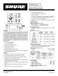
On·Off Switch: applies power to the FP16A circuitry
Power LED: Indicates unit is on.
Input Gain Screwdriver Control: adjusts input signal
level.
Output 1-6 Screwdriver Control: adjusts individual output
channel signal levels.
Norm LED: indicates when internal signal level is
approximately 25 dB below clipping.
Overload LED: indicates when internal signal level
approaches clipping.
Three-Pin XLR 1-6 Output Connectors: provide for
connection to either low-impedance microphone or line
level inputs of power amplifiers, mixers, or other signal
processing equipment.
Mic/Line 1-6 Slide Switches: select microphone or line
level output signal levels.
Phantom On-Off Slide Switch: applies 27 VDC (nominal)
phantom power to pins 2 and 3 of the input connector for
use with condenser microphones. IMPORTANT: Make
certain any condenser microphone used is compatible
with the FP16A phantom circuit, and that the FP16A input
Mic/Line switch is in the Mic position. Do not turn the
Phantom switch on when using unbalanced
low-impedance microphones; objectionable hum will
2