1
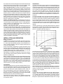
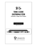
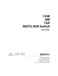
Model FP42 User Guide
Stereo Microphone Mixer
GENERAL
CONTROLS AND CONNECTIONS
The FP42 is a 4-input, 2-output, compact, self-contained stereo
mixer for applications in broadcasting, recording and sound reinforcement. The high-reliability FP42 integrates all the operating
features of a professional stereo mixer in a single unit—small and
lightweight enough for location use, but with the reliability of a studio console.
Power Off/On Switch: applies power to the FP42 circuitry.
Channel Level/Cue Rotary Controls: adjust individual input
channel signal levels. Each channel can be cued by pulling the control knob outward, rotating the knob to the desired level, and pushing the knob inward to activate the channel.
Lo Cut Filter Slide Switches: reduce unwanted low-frequency
signals such as wind noise by 6 dB per octave at 150 Hz.
Pan L--R Rotary Controls: assign each input channel signal to the
left (L) or right (R) output channel, or equally to each output channel
(center detent).
Master Rotary Control: determines mixed output level at left (L)
and right (R) output connectors. The control is “clutched”: both
channel levels can be set simultaneously, or the left (inner knob) or
right (outer knob) channel can be set individually. The control also
sets the tone oscillator level when the Tone Osc switch is turned on.
Mono/Stereo Slide Switch: selects either monophonic output signals (both left and right output connectors carry the same signal) or
stereo operation (input channel signals are assigned to left or right
output channels depending on Pan control positions).
Limiter In/Out Slide Switch: activates fast-acting, peak-responding limiter circuit to cut overload distortion during loud program intervals without affecting normal program levels.
Peak/Limiter LEDS: indicate limiter operation with the limiter in,
and indicate approaching program overload with the limiter out.
The LEDs are activated by the shortest transient peak, but remain
on long enough to provide easy recognition.
L and R VU Meters: indicate 0 VU with a +4 dBm output (recommended for normal use to provide approximately 14 dB headroom
from operating level to clipping level). Rear-panel VU Range +4/+8
slide switch permits changing to 0 VU = +8 dBm. The VU meters are
lit during ac operation only; therefore, the illumination serves as a
visual alarm if the ac is interrupted and the unit has automatically
switched to battery operation.
Batt Check Momentary Push-button Switch: operates in conjunction with the left-channel VU meter to indicate battery condition. With the Power switch on and the switch depressed, a new set
of batteries will give about a +2 VU indication. Battery condition is
good if the reading is above 0 VU: a lower reading means that new
batteries are required for proper operation.
Tone Osc Off/On Slide Switch: provides a highly stable, low-distortion 1-kilohertz tone for line tests and level checks. The tone signal level is controlled by the Master Level control. The tone signal
appears on both the line and microphone outputs, as well as the
Headphones and Mix Bus connectors. The tone oscillator should
be switched off when not in use.
Headphones 1/4-inch Stereo Phone Jack and Miniature 3.5
mm Stereo Phone Jack: permit monitoring mixer output through
most stereo headphones. The Headphones rotary control adjusts
FEATURES
S Wide, flat frequency response, low distortion, and high
output level
S Reliable operation under all temperature and humidity
conditions
S Protected against RF interference and damage from input
overload and shorted outputs
S Four transformer-coupled XLR inputs, each microphone-line
switchable with low-cut filters and cuing function
S Full-separation pan pots with center detent on each input for
precise spatial positioning
S Phantom power for condenser microphone operation
S Built-in tone oscillator permits level checking and line testing
S Left- and right-channel transformer-coupled XLR outputs,
with microphone-line and mono-stereo switches
S Parallel stereo headphone jacks (1/4-inch and mini) with
level control
S Left and right mix bus jacks
S Active, feedback-type input gain controls for high-level input
signals without input attenuators
S Adjustable-threshold limiter with left- and right-channel peak
indicators
S VU meters with range switch and battery check function
S Left- and right-channel master level controls and ganged
headphone level control
S Powered by ac (120 or 240V—internally selectable) or
built-in battery pack
S Low battery drain provides up to 10 hours operation under
normal conditions
S Noiseless and automatic switchover to and from battery
power
S
S
S
S
Rugged, durable construction
Compact and lightweight for field use and transporting
Rack-mountable with accessory rack mount kit
Listed by Underwriters Laboratories, Inc.;
listed by Canadian Standards Association as Certified
ã2003, Shure Incorporated
27A8795 (CD)
Printed in U.S.A.
the output level of both left and right channels. Note that the headphones output level is high enough for use as an auxiliary unbalanced line feed to drive a tape deck or a power amplifier.
Input 1–4 XLR Connectors: are balanced, professional, three-pin
audio connectors. Pins 2 and 3 are “hot,” and pin 1 is ground. For
microphone operation, the Input Mic/Line switches must be in the
Mic position; for line level inputs, the switches must be in the Line
position. Phantom Off/On Slide Switch: controls the application of
phantom power for condenser microphones to all inputs. With the
switch on and Input Mic/Line switches in the Mic position, +30 Vdc
is applied to pins 2 and 3 of each input connector. Series currentlimiting resistance is 3.3 kilohms for each input. When using other
than Shure condenser microphones, verify that the voltage and resistance requirements are compatible.
Output L and R XLR Connectors: are professional, three-pin audio connectors for connection to either low-impedance microphone
or line-level inputs of power amplifiers, mixers, or other signal-processing equipment. The Output Mic/Line switch selects either microphone- or line-level output signals.
Mix Bus L and R Phono Pin Jacks: provide direct access to the
left and right output channel mixing buses. This facilitates stacking
or “multing” FP42s to achieve additional input capacity without losing any inputs. With two FP42s connected at their mix bus jacks, for
example, the left and right mix buses of each unit are directly connected, providing two independent (ganged) master gain controls
and two isolated line amplifiers with eight individually controlled inputs. Since the buses are directly connected, a 6 db drop in the gain
of each output channel will occur, and the master or input controls
must be increased to compensate.
Adjustments
Turn the Power switch to the On position (VU meters will light in ac
operation). Turn the Phantom switch on if non-battery-operated
condenser microphones are to be used with the FP42. (Caution: Do
not turn the Phantom switch on when using unbalanced low-impedance microphones; objectionable hum will result.) Note that phantom power cannot be applied to the inputs with the Mic/Line
switches in the Line position; if line-level condenser microphones
(such as Shure’s SM82) are to be operated on phantom power,
contact Shure’s Customer Services Department for modification instructions.
Turn the Limiter switch to Out. For each input channel, apply an input signal and rotate the associated Pan control to assign the signal
to the left or right output channel as desired. Adjust the Channel
Level control for each channel so that the VU meter needles move
with the audio signals in the 0 VU to –20 VU range, with occasional
movement into the 0 VU to +3 VU (red) area. With the limiter out, the
red Peak/Limiter LEDs will flicker as the signal level approaches
clipping.
If desired, activate the Lo Cut Filter switches above the Channel
Level controls. The filter action will help reduce wind noise and undesirable low-frequency signals such as from condenser microphones or turntable rumble (see Figure 1).
INSTALLATION AND OPERATION
Battery Operation
In addition to 120- or 240-volt ac operation, the FP42 can be operated from an internal battery pack. Current drain is typically 32 mA
at + 4 dBm output level. Battery operation is recommended for remote, on-location operation, and as an emergency backup source
in case of ac power failure.
Access to the battery compartment is through the bottom of the
chassis. Three 9-volt transistor radio batteries power the FP42 at
full rated output. Use alkaline batteries for maximum life. Battery life
is approximately 10 hours at +4 dBm continuous use. Note that
phantom power loading will increase battery drain.
With batteries in the battery compartment, the FP42 will automatically and silently switch to battery operation should the ac voltage
fall below a suitable level.
Battery condition can be determined by using the Batt Check switch
on the front panel. With the FP42 power switch on, activate the Batt
Check switch, and observe the VU meter. A new set of batteries will
give about a +2 VU indication. Battery condition is good if the reading is above 0 VU; a lower reading means that new batteries are
required for proper operation. (Note that the FP42 power switch
must be turned on to check battery condition.)
LO-CUT FILTER ACTION
FIGURE 1
Note that each input Channel Level control has a cuing capability.
To cue a channel while the other channels are carrying program
material, pull the desired channel Level control outward to the cue
position. This removes that channel from the mixing circuitry and
routes it only to the Headphones jacks. Adjust the Headphones level control to a comfortable listening level, and adjust the cued channel Level control for a proper mixing level. Restore the cued signal
to the program mix by pushing the Channel Level control inward.
The limiter circuit is activated by the Limiter switch. With the switch
set to In, mixer output is limited to the preset threshold level of +14
dBm. Increasing the Channel Level or Master gain controls increases the average output and the amount of limiting. To adjust the
limiter threshold, refer to the Service section.
With the limiter circuit in, the Peak/Limiter LEDs light to show limiter
action. The LEDs respond much faster than VU meters and are activated by extremely short transient peaks, but remain on long
enough for easy recognition.
Connections
Connect the signal sources to the three-socket XLR Input connectors and set the Mic/Line switches for the proper level. Connect the
three-pin XLR Output L and R connectors to low-impedance microphone or line-level inputs of power amplifiers, mixers, VTRs, etc.
Set the Output Mic/Line switch for the appropriate signal level.
If desired, connect additional FP42s or other mixers using the Mix
Bus phono pin jacks. A common ground connection can be established using the rear-panel Ground binding post.
Connect the line cord to a 120 Vac +10%, 50/60 Hz source if the
FP42 is to be ac-operated. If 240-volt ac operation is desired, refer
to the Service section.
VU Meter
The VU meters are factory-calibrated for use with a 600-ohm terminated line. The VU Range switch on the rear panel selects either a
+4 or +8 dBm output at 0 VU meter indication. (This switch changes
the meter indication but does not change the actual output level.)
Microphone output levels are 50 dB below line output. The +4 range
2
Distortion
0.4% or less THD, 30 to 20,000 Hz at + 15 dBm output; 0.5% or
less IM distortion at +15 dBm output into 600 ohms
is recommended for normal use to provide approximately 14 dB of
headroom from operating level to clipping level.
The VU meters are illuminated by a single cartridge-type, 6.3V incandescent lamp, operating well under its normal rating for a life expectancy of greater than 10,000 hours. The lamp is only lit for ac
operation. Consequently, the illumination serves as a visual alarm if
the ac is interrupted and the unit has switched to battery operation.
The VU meters are connected on the primary side of the output
transformer to assure protection from any dc level on a telephone
line.
Common Mode Rejection
65 dB minimum with input of – 20 dBV at 100 Hz
Control Interaction
Less than 1 dB with any control combination
Overload and Shorting Protection
Shorting outputs, even for prolonged periods, will cause no damage; microphone input will not be damaged by signals up to 3V
Telephone interconnection
Separation (left and right outputs)
40 dB minimum at 10 kHz; 50 dB minimum at 1 kHz
When using the FP42 connected directly to a telephone line, check
to see whether the telephone company requires an interface coupler between the FP42 and the telephone line. If a coupler is required, make certain the coupler selected and the wiring arrangement are in compliance with local telephone company regulations.
Connect the telephone line to the left or right Output connector and
turn the Pan controls so that the entire output signal is on the telephone-connected output, or switch to mono operation.
Low-Cut Filters
6 dB per octave rolloff at 150 Hz
Limiter
Threshold: Adjustable, +8 to +14 dBm
Attack Time: 3 msec typical
Recovery Time: 500 msec typical
Telephone Line Surge Protection
Peak/Limiter Indicators
Limiter out: lights 6 dB below clipping
Limiter in: lights at onset of limiter action
When using the FP42 connected directly to a telephone line subject
to lightning-induced voltage surges, the following part (commercially available) can be installed across the output terminals to provide additional protection for output circuit components: Metal Oxide Varistor, General Electric Co., Type No. V22ZA1.
Phase
All outputs in phase with all inputs. Pin 2 is “high” with respect to
pin 3; pin 1 is ground. Tip of mix bus jack in phase with pin 3. Tip
and ring of headphone jacks in phase with pin 2 of left and right
outputs, respectively.
SPECIFICATIONS
Frequency Response (ref 1 kHz)
30 to 20,000 Hz, +1, –3 dB
Tone Oscillator
1 kHz; +18 dBm maximum at both outputs with Master level full
up
Voltage Gain (at 1 kHz)
INPUT
OUTPUT
LINE
MICROPHONE
MIX BUS
PHONES
PHONES (CUE)
Mic
90 dB
40 dB
25 dB
100 dB
85 dB
Line
40 dB
–10 dB
–25 dB
50 dB
35 dB
Mix Bus
55 dB
5 dB
–
62 dB
–
Phantom Power
30 Vdc nominal, 3.3k series resistance, automatically disabled
with input switch in Line position
Operating Voltage
Ac Operation: 120 or 240 Vac ±10% (internally selectable),
50/60 Hz, 6W
Dc Operation: 27 Vdc nominal at 30 mA typical no-signal, 32 mA
typical at 0 VU (+4 dBm) output; 21.5 Vdc minimum; battery life
approximately 10 hours with alkaline batteries at +4 dBm output
in continuous use; three 9-volt batteries, type NEDA 1604A
Inputs
INPUT
IMPEDANCE (at 1 kHz)
FOR USE WITH
ACTUAL
INPUT CLIPPING LEVEL
(at 1 kHz)
Mic
19–600 ohms
1k
–40 to –5 dBV*
Line
Less than 10k
66k
+10 to +45 dBV*
3.5k
0 dBV
Mix Bus
3.5k
*Dependent on input control setting.
Temperature Range
Operating: –18° to 57° C (0° to 135° F)
Storage: –29° to 71° C (–20° to 160° F)
Outputs
OUTPUT
IMPEDANCE (at 1 kHz)
OUTPUT CLIPPING LEVEL
(at 1 kHz)
FOR USE WITH
ACTUAL
Mic
150 ohms
<1 ohm
–33 dBV min. across150
ohms
Line
600 ohms
185 ohms
+18 dBm min. across 600
ohms
Mix Bus
3.5k
3.5k
–15 dBV min. across 3.5k
Headphones
8–2000 ohms
100 ohms
+6 dBV min. across 200 ohms
Dimensions
79.5 mm H x 310 mm W x 230 mm D
(3–1/8 in. x 12–7/32 in. x 9–1/16 in.)
Weight
Net: 2.95 kg (6 lb 8 oz)
Packaged: 3.45 kg (7 lb 10 oz)
Noise
Equivalent Input Noise: –129 dBV (low-impedance microphone, 150 ohms, 300 to 20,000 Hz) into 600-ohm load at full
gain
Equivalent Input Hum and Noise: –127 dBV (low-impedance
microphone, 150 ohms, 20 to 20,000 Hz) into 600-ohm load at
full gain
Output Noise: –70 dBV maximum (output control full counterclockwise [off]), –55 dBV maximum (output control full clockwise
[on]) (input control down, 300 to 20,000 Hz)
Output Hum and Noise: –62 dBV maximum (output control
down), – 53 dBV max. (output control up, input control down, 20
to 20,000 Hz)
Certifications
Listed by Underwriters Laboratories, Inc.; listed by Canadian
Standards Association as Certified
ACCESSORIES
The Model A16R Rack Panel Kit consists of a 19 in. x 3–1/2 in.
(483 mm x 89 mm) precut rack panel and necessary hardware for
rack-mounting the FP42 with its cover in place and end caps removed in a standard 19” (483 mm) rack panel.
3