1
Hotwire® ReachDSL™ Modem, Model 6390
with Inline Phone Filter
Installation and Operation Supplement
Document Number 6390-A2-GK40-00
September 2002
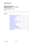
Contents
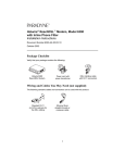
Hotwire 6390 ReachDSL Modem Overview ...................................................... 2
Hotwire ReachDSL System ......................................................................... 3
Power-On ........................................................................................................... 4
Status LEDs ................................................................................................ 4
Troubleshooting ................................................................................................. 5
Increasing the Number of End-User Systems ................................................... 6
Optional ReachDSL Modem Wall Placement .................................................... 8
ReachDSL Modem Hardware Template ...................................................... 9
Hotwire 6390 ReachDSL Modem Commands ................................................... 10
Downloading Hotwire 6390 ReachDSL Modem Software ................................. 11
Building a Management PVC to the Model 8355 Line Card in an 8820
GranDSLAM Network .................................................................................. 12
Building a Management PVC through the 4200 GranDSLAM System ........ 14
Downloading Software to the ReachDSL Modem ....................................... 15
Technical Specifications for Hotwire 6390 ReachDSL Modem .......................... 16
6390-A2-GK40-00
September 2002
1
Hotwire 6390 ReachDSL Modem Overview
The Hotwire® 6390 ReachDSL™ Modem is a component in the Hotwire
ReachDSL System and interoperates with the Hotwire 8355 ReachDSL Card in
the Hotwire 8820 GranDSLAM™ system and in the 4200 GranDSLAM system.
The GranDSLAM system provides high-speed Internet or corporate LAN access
over traditional twisted-pair copper telephone wiring.
The ReachDSL technology:
Operates over existing copper wire with existing telephone jacks.
Uses an inline phone filter on the modem’s PHONE jack.
Includes a second line pass-through from the ReachDSL modem’s LINE jack
to PHONE jack to accommodate an attached 2-line telephone.
Provides adaptive data rates to dynamically adapt and allocate bandwidth to
optimize applications.
Refer to the Hotwire ReachDSL Modem, Model 6390 with Inline Phone Filter,
Installation Instructions, Document Number 6390-A2-GN10, for instructions on
how to install the Hotwire 6390 ReachDSL Modem.
2
September 2002
6390-A2-GK40-00
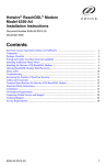
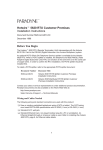
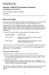
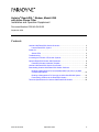
Hotwire ReachDSL System
Copper pairs run from the central office (CO) to the customer premises (CP) to
create the local loop. The local loop terminates on the customer premises at the
demarcation point.
Customer Premises (CP)
Filter
Central
Office
(CO)
Local Loop
Network
Service
Provider
(NSP)
Demarcation
Point
DSL/POTS
ReachDSL
Modem
Standard
Ethernet
Cable
Standard
Ethernet
Cable
or
DSL – Digital Subscriber Lines
POTS – Plain Old Telephone Service
End-user
Systems
Hub
02-17237
NOTES:
In this document:
— A telephone is used to represent any equipment that plugs into a phone
jack and uses the POTS line, such as a phone, modem, or fax machine.
— End-user system is used to represent any PC with an Ethernet connection
and ReachDSL-based service.
— RJ11 wall jack is used to represent either an RJ11 or an RJ14 wall jack.
The RJ14 wall jack is used for a phone with two lines.
— Service provider is used to represent any Internet Service Provider (ISP)
or remote LAN access provider.
6390-A2-GK40-00
September 2002
3
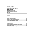
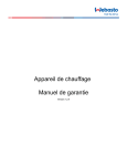
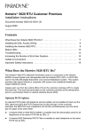
Power-On
When power is applied, the ReachDSL modem performs self-diagnostics and the
PWR LED is on. The self-diagnostics includes a power-on self-test and all of the
LEDs turn on for one second.
Power – green
Alarm – red
Test – yellow
DSL Line – green
Transmit/Receive – green
Ethernet Link – green
PWR
ALM
TST
LINE
TX/RX
ETHERNET
ReachDSL
01-17003
Status LEDs
All of the LEDs turn on and off during the power-on self-test. After a successful
self-test, the LEDs should appear as indicated in BOLD in the Condition column
below.
LED
Condition Status
PWR
ON
ReachDSL modem has power.
ALM
OFF
No active alarms.
ON
An alarm condition exists.
OFF
No active tests.
ON
The TST LED is on during the power-on self-test and during a
test initiated by the service provider.
ON
The DSL link is active and ready to transmit and receive data.
OFF
The DSL link has not been established.
ON
Data transmission is in progress on the DSL line.
OFF
The modem is not transmitting or receiving data.
TST
LINE
TX/RX
ETHERNET ON
OFF
The Ethernet connection to the Ethernet hub or PC is active.
No Ethernet 10BaseT device is detected.
Refer to Troubleshooting on page 5 for LED indications requiring action.
4
September 2002
6390-A2-GK40-00
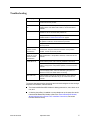
Troubleshooting
LED Symptom
Action
All LEDs are on.
If LEDs remain on after ten minutes, the modem is not functional.
Contact the service provider.
ALM LED remains
on.
The power-on self-test may have failed. Unplug the unit and
reapply power. If the alarm LED is still on, contact the service
provider.
Ethernet LED is off.
Verify that the Ethernet cable is securely installed at both ends, and
at least one PC is connected and powered on.
Verify that the correct straight-through or crossover cable is
installed. Refer to Cables & Connectors on page 6.
LINE LED is off.
Verify that the DSL LINE cable is securely installed on both ends. If
the problem continues, contact the service provider.
Verify that the line has dial tone. If there is no dial tone, contact the
service provider.
LINE LED is on and
there is no data
transmission.
The DSL link has been established but there is no data
transmission. Verify the Ethernet connection. If the problem
persists, contact the service provider.
LINE and Ethernet
LEDs are on and
there is no data
transmission.
The DSL and Ethernet links have been established but there is no
data transmission. If the problem continues, contact the service
provider.
PWR LED is off.
Check that the power cord is securely installed on both ends.
If no LEDs are on, the power supply may be defective. Test the
outlet to verify power. If the problem persists, contact the service
provider.
If other LEDs are on, the PWR LED may be burned out. Unplug the
unit and reapply power; watch all LEDs during the power-on
self-test to verify if the PWR LED is functioning.
TST LED is on.
A test initiated by the service provider may be active. Wait five
minutes. If the TST LED does not go off, contact the service
provider.
To improve data transmission throughput and minimize background noise during a
telephone conversation, make sure that:
6390-A2-GK40-00
The Hotwire 6390 ReachDSL Modem is always powered on, even when not in
use, and
A Hotwire phone filter is installed on every telephone on the same line as the
Hotwire 6390 ReachDSL Modem (refer to the Hotwire ReachDSL Modem,
Model 6390 with Inline Phone Filter, Installation Instructions, Document
Number 6390-A2-GN10).
September 2002
5
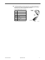
Increasing the Number of End-User Systems
A single end-user system is attached to the Hotwire 6390 ReachDSL Modem by
using an Ethernet straight-through cable. To increase the number of end-user
systems, connect all the PCs to an Ethernet hub and connect the modem to the
hub’s uplink port using a standard straight-through cable for both connections.
The Hotwire ReachDSL port card supports 32 hosts/subnets per DSL port and the
Hotwire ReachDSL Modem supports up to 256 MAC entries.
Cables & Connectors
Standard twisted-pair CAT3 or better cables are recommended.
The LINE and PHONE interface connectors
use 6-pin, non-keyed modular plugs. RJ11 or
RJ14 6-pin connectors can be used.
6-Pin
RJ11 Plugs
Line & Phone Connectors
Pin # Function
6
1
Not used
2
Ring 2 (optional)
3
DSL Ring 1
4
DSL Tip 1
5
Tip 2 (optional)
6
Not used
Pin #6
Pin #1
98-15304a
The LINE and PHONE jack pinouts are either filtered or unfiltered for POTS.
PHONE Jack Pinouts
LINE Jack Pinouts
Pin # 3, 4
Filtered for POTS
Pin # 3, 4
DSL and POTS
Pin # 2, 5
2nd POTS unfiltered
Pin # 2, 5
2nd line pass-through
September 2002
6390-A2-GK40-00
The Ethernet interface connector uses an 8-pin, non-keyed modular plug. To
connect the DSL modem to an uplink port on an Ethernet hub or PC with an
Ethernet NIC card, use the straight-through connection.
8-Pin Straight-through Connection
Ethernet
Cable
Pin # Function
1
10BaseT RXD+
2
10BaseT RXD–
3
10BaseT TXD+
4&5
Not used
6
10BaseT TXD–
7&8
Not used
8-Pin
Plug
Pin #8
Pin #1
6390-A2-GK40-00
September 2002
98-16055a
7
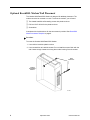
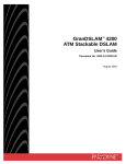
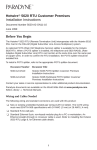
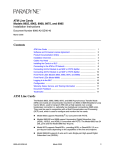
Optional ReachDSL Modem Wall Placement
The Hotwire 6390 ReachDSL Modem is designed for tabletop placement. The
modem can also be mounted on a wall. To mount the modem, you will need:
❑ Two slotted-head #6 self-threading screws with plastic anchors
❑ Drill and 3/16" drill bit for the plastic anchors
❑ Screwdriver
A template with the dimensions for the two screws is provided. See ReachDSL
Modem Hardware Template on page 9.
Procedure
To mount the Hotwire 6390 ReachDSL Modem:
1. Use a drill to install the plastic anchors.
2. Use a screwdriver to install the screws. Do not install the screws flush with the
wall. Leave enough clearance to hang the modem housing from the screws.
Wall
Fasteners
Hotwire
ReachDSL
Modem
01-17004
8
September 2002
6390-A2-GK40-00
Bottom
12.95 cm
or
5.10"
Top
ReachDSL Modem Hardware Template
02-17014-01
6390-A2-GK40-00
September 2002
9
Hotwire 6390 ReachDSL Modem Commands
The Hotwire 6390 ReachDSL Modem provides the commands listed in Table 1,
Hotwire ReachDSL 6390 Modem Commands. Use a PC connected to the
Ethernet jack on the rear panel of the modem or Telnet into the modem to enter
these commands.
Table 1. Hotwire ReachDSL 6390 Modem Commands (1 of 2)
Command Syntax
Argument Function
Displays help information.
help {all<command>}
info
Description
all
command
No argument
None
mgmtpvc {dhcp<IP address>
<gateway>}
None
Model Number
Serial Number
Firmware Revision
Hardware Revision
DSP Revision
Configures or displays the management PVC.
No argument
dhcp or ip address
Current configuration
Configures the management PVC:
– dhcp
Example: mgmtpvc dhcp
– The management PVC acquires its
address using DHCP
– IP address gateway
Example: mgmtpvc
135.26.95.1 135.26.95.6
– The management PVC is configured for
the specified IP address and gateway
Configures the modem’s password(s).
login
Example: password user user
password
Example: password secret
ping
Only available to “admin” users. Can either
be “admin” (default) or “user”
password
Only available to “admin” users. Initiates a ping
to the specified IP address and displays
results.
10
Displays syntax for command
Terminates the Telnet session.
password [<login>] <password>
reset
Displays a list of all valid commands and
their syntax
Displays device information.
logoff
Displays a list of all valid commands
<IP address>
Example: ping 135.26.12.254
None
An IP address must be specified
Resets the unit.
September 2002
6390-A2-GK40-00
Table 1. Hotwire ReachDSL 6390 Modem Commands (2 of 2)
Command Syntax
Argument Function
Description
Initiates a firmware upgrade and resets the
modem.
upgrade <IP address> [me]
<remote file name>
IP address
m or e
The decimal IP address of the TFTP server
The interface over which to perform TFTP
– m
– Management PVC interface
– e
– Ethernet interface
Remote file name
Name of the new firmware file on the TFTP
server
Downloading Hotwire 6390 ReachDSL Modem Software
The Hotwire 6390 ReachDSL Modem is capable of receiving a download of its
software while continuing to pass data. The Hotwire 6390 ReachDSL Modem acts
as a Trivial File Transfer Protocol (TFTP) server while receiving a download
through its DSL interface.
To perform a software download, you must use a PC containing a TFTP client
running on Windows 2000, Windows NT, or a UNIX platform. The download
process differs, depending on whether the modem is in an 8820 GranDSLAM
network with a Model 8355 Line Card or a 4200 GranDSLAM network.
See the following for procedures:
6390-A2-GK40-00
Building a Management PVC to the Model 8355 Line Card in an 8820
GranDSLAM Network on page 12
Building a Management PVC through the 4200 GranDSLAM System on
page 14
Downloading Software to the ReachDSL Modem on page 15
September 2002
11
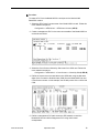
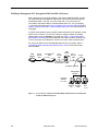
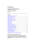
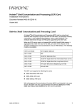
Building a Management PVC to the Model 8355 Line Card in an
8820 GranDSLAM Network
Before attempting to download software to the Hotwire 6390 ReachDSL modem,
you must first build a management Permanent Virtual Circuit (PVC) through the
DSLAM (including the SCM card). To do this, you must create VPI 0, VCI 33 on the
Model 8355 line card port connected to the 6390 modem to be downloaded (see
Figure 1, Network View of Hotwire 6390 ReachDSL Modem Software Download in
an 8820 GranDSLAM System, and the procedure on next page).
In DHCP mode (default mode), the 6390 modem discovers the IP address via the
DHCP server. However, you can also choose to configure a static IP address
(Static mode) using the mgmtpvc command (see Table 1, Hotwire ReachDSL
6390 Modem Commands) via a PC attached to the 6390 modem’s Ethernet port.
The PC must have an IP address of 135.26.6.xxx with a Class C subnet mask.
For more information on the Model 8355 line card, see the Hotwire ATM Line
Cards, Models 8335, 8355, 8365, and 8385, User’s Guide, Document Number
8335-A2-GB20.
GranDSLAMTM
8820
6390
Endpoint
Reach
DSL
VPI=0
VCI=33
POWER
A
VPI=0
VCI=33
ALARMS
B
Fan Major Minor
ATM
ATM
Switch
ATM
VPI=0
VCI=33
Router
ATM
PWR
ALM
TST
1483 Routed
Encapsulation
TX/RX
POWER ENTRY MODULE
LEFT UNIT: LINE A
RIGHT UNIT: LINE B
WARNING! POWER MUST BE
BEFORE REMOVING OR
DISCONNECTED AT THE
INSTALLING THIS PWR ENTRY SOURCE
MODULE
POWER ENTRY MODULE
LEFT UNIT: LINE A
RIGHT UNIT: LINE B
48V NEG
48V RTN
NET
48V NEG
ETHER
48V RTN
LINE
CLOCK SERIAL
AC
A
MCC ALARM
2
4
6
8
B
SERIAL ALARM
CLOCK SMCM
1
3
5
7
LAN/WAN SLOT
A
10
12
14
16
18
11
13
15
17
WARNING! POWER MUST BE
BEFORE REMOVING OR
DISCONNECTED AT THE
INSTALLING THIS PWR ENTRY SOURCE
MODULE
9
B
IP Address
Gateway
Ethernet
Management
Network
Customer
Network
IP = xxxx
Windows Windows
NT
2000
Figure 1.
12
Unix
02-17319
Network View of Hotwire 6390 ReachDSL Modem Software Download in
an 8820 GranDSLAM System
September 2002
6390-A2-GK40-00
Procedure
To create a PVC from the Model 8355 line card port to the Hotwire 6390
ReachDSL modem:
1. Select the ATM Cross Connect screen from Model 8355 line card. Follow this
menu selection sequence:
Configuration → ATM Switch → ATM Cross Connect (A-E-B)
2. Create a management PVC in the cross connect table of the Model 8355 line
card as shown below:
3. Select the Cross Connect Sorted by Slot screen from SCM card. Follow this
menu selection sequence:
Configuration → ATM Switch → Cross Connect → Sorted by Slot (A-E-B-B)
4. Define the custom cross connect table on the SCM card using the last three
digits of the Connection Serial Number (CSN) from the Model 8355 line card
Cross Connect screen. In this example, use the 002 portion of the 13C01:002
CSN.
5. Define a management PVC path across the ATM network to reach the
Model 8355 line card 0/33 management PVC using 1483 routed
encapsulation.
6390-A2-GK40-00
September 2002
13
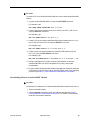
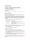
Building a Management PVC through the 4200 GranDSLAM System
Before attempting to download software to the Hotwire 6390 ReachDSL modem,
you must first build a management Permanent Virtual Circuit (PVC) through the
GranDSLAM 4200. To do this, you must create VPI 0, VCI 33 on the port
connected to the 6390 modem to be downloaded and a VPI, VCI (for example,
1, 33) on the uplink side (see Figure 2, Network View of Hotwire 6390 ReachDSL
Modem Software Download in a 4200 GranDSLAM System, and the procedure on
next page).
In DHCP mode (default mode), the 6390 modem discovers the IP address via the
DHCP server. However, you can also choose to configure a static IP address
(Static mode) using the mgmtpvc command (see Table 1, Hotwire ReachDSL
6390 Modem Commands) via a PC attached to the 6390 modem’s Ethernet port.
The PC must have an IP address of 135.26.6.xxx with a Class C subnet mask.
For more information on the GranDSLAM 4200 and CLI commands, see the
GranDSLAM 4200 ATM Stackable DSLAM User’s Guide, Document Number
4200-A2-GB20.
6390
Endpoint
GranDSLAMTM
4200
VPI=0
VCI=33
ATM
VPI=1
VCI=33
ATM
Switch
ATM
VPI=1
VCI=33
Router
ATM
RTN -48VDC
ALARM
3.5 A 60
B
CONSOLE
PWR
A
B
BITS
MGMT
ALM
TST
LINE
ALRM
TEST
POWER
DSL
STATUS
UPLINK
A
Reach
4202
E1 MODULE
TX
75W
RX
100/120W
TX/RX
ETHER
1
13
NET
4
16
8
20
12
24
DSL PORTS
1-24
POTS
1-24
1483 Routed
Encapsulation
IP Address Gateway
Ethernet
Management
Network
Customer
Network
IP = xxxx
Windows Windows
NT
2000
Figure 2.
14
Unix
02-17320
Network View of Hotwire 6390 ReachDSL Modem Software Download in
a 4200 GranDSLAM System
September 2002
6390-A2-GK40-00
Procedure
To create a PVC from the GranDSLAM 4200 port to the Hotwire 6390 ReachDSL
modem:
1. Log into the GranDSLAM 4200 unit using the ACT-USER command.
For example, type:
ACT-USER:TAMPA:SUPERUSER:100::********
2. Create a VCL to the upstream network (on the NT) with VPI=1 and VCI=33
using the ENT-VCL command.
For example, type:
ENT-VCL:TAMPA:NTVCL-1-33:100::1,1;
3. Create a VCL to the Hotwire 6390 ReachDSL Modem attached to Port 1 (on
the LT) with VPI=0 and VCI=33 using the ENT-VCL command.
For example, type:
ENT-VCL:TAMPA:LTVCL-1-1-1-1-0-33:100::1,1;
4. Create a cross connection between the upstream ATM network (NT) and
Port 1 (LT) using the ENT-CRS-VC command.
For example, type:
ENT-CRS-VC:TAMPA:NTVCL-1-33,LTVCL-1-1-1-1-0-33:100::::IS;
5. Define a management PVC path across the ATM network to reach the
GranDSLAM 4200 1/33 uplink management PVC using 1483 routed
encapsulation.
6. Ping the Hotwire 6390 ReachDSL Modem Management IP address assigned
by the DHCP server (DHCP mode) or manually (Static mode) using the ping
command (see Table 1, Hotwire ReachDSL 6390 Modem Commands).
Downloading Software to the ReachDSL Modem
Procedure
To download new software to the Hotwire 6390 ReachDSL Modem flash memory:
1. Telnet to the 6390 modem.
2. Use the upgrade command to begin the software download (see Table 1,
Hotwire ReachDSL 6390 Modem Commands). The modem is automatically
reset after a successful download.
6390-A2-GK40-00
September 2002
15
Technical Specifications for Hotwire 6390 ReachDSL Modem
Item
Specification*
Height x Width x Depth
3.71 cm x 14.54 cm x 11.00 cm (1.46" x 5.72" x 4.33")
Weight
0.20 kg (0.45 lb.)
Power
Class 2 Transformer normal
service input voltage range
Input: 100 VAC (+10%), 50 Hz;
120 VAC (+10%), 60 Hz; or
230 VAC (+10%), 50/60 Hz
Output: 5 VDC nominal, minimum 0.6A (SELV)
Approvals
FCC Part 15
Class B digital device
CISPR 22
Class B
Other Certifications
Refer to equipment’s label for approvals on product
Physical Environment
Operating temperature
0° C to 40°C (32°F to 104°F)
Storage temperature
–30°C to 70°C (–22°F to 158°F)
Relative humidity
5% to 95% (noncondensing)
Shock and vibration
Withstands normal shipping and handling
Heat Dissipation
2.35 watts at 5.0 VDC (nominal input voltage)
Interface Connectors
Line Interface
RJ11 or RJ14 6-pin
Ethernet Type II Frame
10BaseT 8-pin
* Technical Specifications subject to change without notification.
16
September 2002
6390-A2-GK40-00
Warranty, Sales, Service, and Training Information
Contact your local sales representative, service representative, or distributor
directly for any help needed. For additional information concerning warranty, sales,
service, repair, installation, documentation, training, distributor locations, or
Paradyne worldwide office locations, use one of the following methods:
Internet: Visit the Paradyne World Wide Web site at www.paradyne.com.
(Be sure to register your warranty at www.paradyne.com/warranty.)
Telephone: Call our automated system to receive current information by fax or
to speak with a company representative.
— Within the U.S.A., call 1-800-870-2221
— Outside the U.S.A., call 1-727-530-2340
Document Feedback
We welcome your comments and suggestions about this document. Please mail
them to Technical Publications, Paradyne Corporation, 8545 126th Ave. N., Largo,
FL 33773, or send e-mail to [email protected]. Include the number and
title of this document in your correspondence. Please include your name and
phone number if you are willing to provide additional information.
Trademarks
Hotwire is a registered trademark of Paradyne Corporation. GranDSLAM and
ReachDSL are trademarks of Paradyne Corporation. All other products and
services mentioned herein are the trademarks, service marks, registered
trademarks, or registered service marks of their respective owners.
Copyright © 2002 Paradyne Corporation. Printed in U.S.A.
6390-A2-GK40-00
September 2002
17
*6390-A2-GK40-00*