1
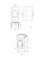
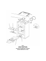
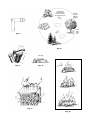
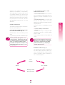
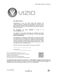
ALPHA II
Instruction Manual
Fig. 1
Fig. 2
Fig. 3
Version: Stahlmantel
Version: Steel casing
Versione: rivestimento in acciaio
Version: Manteau en acier
Fig. 4
Fig. 5
Fig. 6
Version: Speckstein
Version: Whetstone
Versione: rivestimento in steatite
Version: stéatite
Kohlendioxid
Carbon dioxide
Anidride carbonica
Dioxyde de carbone
Sauerstoff
Oxygen
Ossigeno
Oxygène
CO
Fig. 7
≈7c
H 2O
O
2
CO
2
2
m
Fig. 8
25 c
m
≈ 1,6 kg
Fig. 10
Fig. 9
Fig. 11
Fig. 12
Wasser
Water
Acqua
Eau
L
I
S
T
O
F
C
O
N
T
E
N
T
S
Overview of technical data and spare parts
19
1. I M P O R TA N T I N F O R M AT I O N
General warning and safety instructions
20
Before installing the appliance
20 - 21
INFORMATION ON HEATING PRACTICE
Suitable fuels and quantities
22
Fuel quantities
22
Maximum fuel quantities
22
Clean combustion
23
Burning of wood
23
2 . I N S TA L L AT I O N O F T H E A P P L I A N C E
Changing the draw plate
24
Inserting the whetstone panels
24
Connecting to the chimney
24
3 . O P E R AT I O N
Firing up
25
The ash drawer
26
Actuation of the vibrating grate
26
Damper settings for nominal heating performance
26
4. CLEANING AND MAINTENANCE
General maintenance
27
TROUBLESHOOTING
What to do if . . . ?
28
5. G UARANTE E
We guarantee
55 - 56
Guarantee card
55 - 56
E X P L A N A T I O N
Important instructions
Practical advice
Use the fold out plan for assistance
18
O F
S Y M B O L S
TECHNICAL DATA
Dimensions (mm) and weights (kg)
Height
Width
Depth of the corpus
Weight with steel casing
Weight with stone casing
Smoke flue outlet diameter
Nominal heating power (DIN 18891)
Lowest heating power
Space heating capacity (m³) –
dependent on house insulation
Fuel flow
Efficiency
CO2 content
CO emission rel. 13% O
Dust emissions
905
516
395
115
155
130
7 kW
3,5 kW
70-190
1,4 kg/h
78,9 %
10,2 %
734 mg/Nm3
29 mg/Nm3
Exhaust gas values for multiple use of the chimney
in accordance with DIN 4705, Part 3/chimney
dimensions to DIN 4705, Part 2
Exhaust gas mass flow g/s
8,68
Exhaust gas temperature °C
268,5
Minimum feed pressure at rated useful
12
heat Pa
1. I M P O R TA N T I N F O R M AT I O N
GENERAL WARNING AND
SAFETY INSTRUCTIONS
➧
bited.
The introductory general warning and
safety instructions must be unconditionally observed
➧
➧
➧
Only an approved means of transport,
distancefrom the heating appliance -
E NG LI S H
Danger of fire!
be used to transport your heating appliance.
➧
Your heating appliance is not suitable for
When operating your heating appliance,
the use of easily flammable and explosive
use as a ladder or supporting platform.
➧
Frames or racks for drying items of clothing,
or similar, must be placed at an adequate
with adequate load carrying capacity must
➧
Do not dry items of washing on the
appliance.
Before commissioning the heater, read
this handbook thoroughly in its entirety.
➧
The placing of non-heat resistant objects
on or near the heating appliance is prohi-
substances in the same or an adjoining room
is prohibited.
The burning of fuel releases heat energy,
leading to considerable heating of the
surface of the heating appliance, the doors,
BEFORE INSTALLING THE APPLIANCE
the door and operating handles, the door
1 .1 Floor load capacity:
glazing , the smoke flue and in some circum-
Before installing the appliance, make sure
stances, the front wall of the appliance
that the load carrying capacity of the floor
Contact with these components without
sub-structure is adequate to withstand the
appropriate protective wear, such as heat
weight of the heater.
protective gloves, or actuating means, must
be avoided.
➧
SAFETY DISTANCES (Minimum distances) Fig. 2
Make your children aware of these special
1. For non-combustible objects
a > 100 mm
b > 400 mm
dangers and ensure that they do not have
2. For combustible objects and supporting walls
in reinforced concrete
a > 200 mm
b > 800 mm
c > 200 mm
access to the appliance when it is in use.
➧
Burn exclusively the approved heating
materials stated in the section on “Clean
1 . 2 Smoke flue connection
combustion”.
➧
c > 100 mm
Smoke flues are a special source of danger
The combustion or introduction of readily
in view of the poisonous gas outlet and fire
combustible or explosive matter, such as
hazard. Engage the services of a franchised
empty spray cans and the like, into the
dealer for their location and installation.
combustion chamber, or their storage in
close proximity to the appliance is strictly
When connecting your flue to the heater in
forbidden, due to the danger of explosion.
the vicinity of wood clad walls, please observe
➧
the appropriate installation guidelines.
No loose or bulky or easily flammable
clothing should be worn when attending
the heating process.
20
1.3
1.7
Be sure to note the build-up of flue gases
When opening the doors on your appliance
under unfavourable weather conditions
and when actuating the controls, use the
(Weather inversion) and the flue draft
tools provided with your heater for these
behaviour.
purposes, i.e. the protective gloves and the
If too little air for combustion is taken in,
operating tools.
this can lead to fumes in the room in which
escape of flue gases. In addition, damaging
Heating appliance - Construction type 1
deposits can be formed in the appliance
(BA 1):
and in the chimney.
This must only be operated with the fire-
In the event of the escape of fumes, let the
box door closed.
fire go out and check that all the air inlet
1.9
openings are unobstructed and that the
The fire box door must only be opened for
flue gas ducting and flue are clean. In case
the charging of fuel and must then be clo-
of doubt, advise a registered chimney
sed again, otherwise this can lead to the
sweep, since inadequate draft conditions
endangering of other fire places/heating
may be associated with your chimney.
appliances also connected to the chimney.
1.4
1 . 9 .1
Before adding new fuel, rake the existing
When the appliance is not being used, the
incandescent residue into a single bed of
firebox door should be kept closed.
material.
1 .10
1.5
The use of wet material as fuel, with too
Only use the tool specified in our range of
much throttling , can lead to sooting-up of
accessories for the purpose of raking the
the chimney, i.e. to the deposit of easily
material together and ensure that no glowing
flammable substances such as soot and tar,
ashes fall from the combustion chamber
possibly leading to a chimney fire.
onto combustible material.
Should this occur, close all air inlets and
1.6
flaps. Call the fire service and withdraw to a
Brown coal briquettes, separated by about
place of safety, together with all the
a finger’s breadth should be laid in a single
occupants of the building.
layer on the glowing material.
Caution: Due to the size of the fire box door,
it is necessary, particularly during heating up,
when the flames are high, not to open the
door too abruptly, in order to prevent the
emergence of flames from the appliance.
21
E NG LI S H
1.8
the appliance is located, or result in the
I N F O R M AT I O N O N H E AT I N G P R A C T I C E
SUITABLE FUELS AND QUANTITIES
MAXIMUM FUEL QUANTITIES
Your appliance is basically suitable for
Wood: (Fig. 9, 10)
the burning of dry chopped firewood. In
2 logs
addition, you can burn fuels such as wood
Brown coal briquettes:
briquettes and brown coal briquettes.
3 items
E NG LI S H
Use only dry material for burning. The
approx. 0.8 kg
approx. 0.5 kg
burning of refuse of any kind, particularly
Wood briquettes (Broken):
plastics, will damage your appliance and the
2 items
chimney and is prohibited by the statutory
Control of the power output of your appli-
regulations on emissions.
ance is obtained by means of the air intake
approx. 0.8 kg
damper. Since the power of your firing
FUEL QUANTITIES
appliance is also dependent on the chimney
The appliance is designed with a flat firing
draft, this air intake damper must be regula-
layout, due to its style of construction. This
ted in accordance with your own experience
means that only one layer of fuel must be
of the operation of the system.
placed on the existing glowing embers
Operation of the secondary air intake regulator, the primary air intake regulator and the
vibrating grate lever, must only be undertaken
using the claw tool provided.
when re-charging. Please note, that if a
greater quantity of fuel is added to your
firing appliance, it will output more heat
and will heat up in excess of the intended
design limits. This may result in damage to
the appliance.
22
Satisfying the challenges of our time
2. THE CORRECT QUANTITY AND
SIZES OF WOOD FUEL
implies the acceptance of responsibility.
The conservation of nature is now one of
➧
our greatest challenges. Our products are
ting. The material is overloaded and your
developments that correspond to the latest
appliance generates undesirable flue gas
state of the art technology. This is an essen-
values.
tial prerequisite for the clean, efficient
Too much wood fuel results in overhea-
Too little wood fuel, or the use of logs
➧
and law-abiding functioning of our firing
that are too large, results in the firing
appliances.
CLEAN COMBUSTION
ting temperature.
The following are important to the achieve-
values.
This also results in undesirable flue gas
ment of clean combustion:
Correct quantity of wood fuel:
(Fig. 10)
➧
1. THE WOOD TO BE BURNED MUST BE
DRY AND UNTREATED. (Fig. 11)
For wood ≈ 1.6 kg (2 logs) per layer
Standard value ‹ 15 % rel. humidity in the
(Standard value), with a nominal heating
wood.
power of 6 kW.
Lowest heating power (3 kW) ≈ 0.8 kg
2 - 3 years drying and well ventilated storage.
(1 log).
A chimney-installed firing appliance is not a
“refuse incinerator”. The burning of refuse and
non-permitted material such as plastic, treated
wood, etc., renders the guarantee null and
void! Further consequences are damage to and
soiling of the equipment and chimney - and of
the environment!
Caution: Only wood briquettes and brown coal
briquettes are to be burned in your firing appliance. Under no circumstances must plastics,
treated wood materials (e.g. chipboard), pit
coal and textiles be burned.
BURNING OF WOOD (Fig. 8)
The clean burning of wood corresponds to
the same chemical process as natural rotting , i.e. the liberated CO 2 (carbon dioxide)
does not increase or debit the balance of
CO 2 in the atmosphere.
Plant
Growth
Wood
CO 2 - content
Rotting of wood
Burning of wood
23
E NG LI S H
appliance not reaching the optimum opera-
2 . I N S TA L L AT I O N O F T H E A P P L I A N C E
CHANGING THE DRAW PLATE
(Fig. 5)
2. Chisel out (or drill out) the hole in the
If the draw plate or the draw-deflector is to
3. Brick in the shell lining.
masonry work.
be replaced on your firing appliance, lift the
First seal the shell lining with mineral wool.
Then fill the area with heat-resistant mortar
or equally suitable filler.
draw plate slightly to the side and remove
the side fireclay component.
You can now tilt the draw plate and remove
E NG LI S H
it from the firebox opening.
4. When the mortar has hardened and
after the filling and smoothing , position
Before initial commissioning or after re-locating the appliance, cleaning and servicing,
make sure that the draw plate (Fig. 5, Part
18), and the wood collector (Fig. 5, Part 21)
are correctly positioned.
When using a flue with a throttle flap, this
must be open.
the base plate and floor protection
(Carton).
5. The unit can now be lifted carefully onto
the base plate.
Under no circumstances must the appliance
be pushed over an unprotected floor.
On this firing appliance, it is necessary to
ensure that the chimney draft reaches at
least the prescribed value (> 0.8 mbar).
If there is a problem in achieving this value,
contact your chimney sweep/maintenance
engineer.
A suitable covering for the floor is provided
by using strong corrugated paper, carton or,
for example, a piece of used carpet. The
aplliance can be safely pushed over such a
protective layer.
If you do not use our original flue compo-
INSERTING THE WHETSTONE PANELS
nent for the chimney connection, then we
Insert the lugs on the pre-mounted carrier
recommend the use of a tube manufactured
plate of the (Right or left) whetstone panel
from steel sheet at least 2 mm thick. Under
(With the opening pointing downwards)
no circumstances must the connection
into the cut-out slots on the oven side wall
component protrude into the chimney
and allow the whole panel unit to slide
duct itself! Seal the gap between the flue
slowly downwards, whilst pressing against
pipe and the shell lining with a ceramic seal.
the oven body. Insert the opposite panel by
the same method.
The installation must satisfy the relevant
safety and building regulations. Please contact
your registered chimney sweep/maintenance
engineer. Who will be pleased to advise you.
CONNECTION TO THE CHIMNEY
On establishing a new connection in a
brick-built chimney, the following proce-
If you use a “system” chimney (e.g. glazed
fireclay) - we would advise you to follow
precisely the connection instructions of the
manufacurer.
dure is recommended:
1. Measure out and mark-off the position
of the chimney connection (if necessary,
taking account of the base plate thickness).
24
3 . O P E R AT I O N
FIRING UP (Fig. 12)
3.
In order to suppress the emission of pollu-
Now ignite the paper. Wait until the soft-
tants as far as possible, we would ask you -
wood chippings are burning well.
for the sake of the environment - to adhere
Several minutes later, close the vibrating
to the following instructions for heating up
grate actuator and the primary air damper.
your firing appliance.
A few minutes later, adjust the secondary
air damper to the ideal settings.
1.
low atmospheric pressure prevails, it is
When the burning has finished, lay about
recommended that initially you burn some
1.8 kg of wood (2 logs) in the firebox. Open
paper, to “drive” the coldness from the
the vibrating grate actuator and the prima-
appliance and the chimney.
ry air damper, until the wood is burning well
(approx. 2 min.). The secondary air damper
2.
should remain at the ideal setting.
For the purpose of heating up, first lay
For each further layer of fuel, proceed in
some uncoated paper on the floor of the
the same way.
firebox and on top of this place 0.5 kg of
5.
softwood chippings and 1.4 kg of wood (2
The remnants of the combustion on the
logs).
firebox floor are the mineral components
Pull the vibrating grate actuator (Part 23)
of the wood (approx. 1 %).
fully out and open the primary air damper
This ash is an excellent fertiliser for all the
(Part 6) and the secondary air damper
plants in the garden, because it is a purely
(Part 4).
natural product. However, the ash should
first be left to accumulate and then be
Please do not use gloss paper or paper from
magazines. These types of paper do not
burn well and they generate very poisonous
substances in the flue gases.
“quenched” with water.
25
E NG LI S H
4.
If your appliance and chimney are cold, or if
Caution: Burning embers can still be present
in the ash. Therefore only empty the ash into
a non-flammable container and do not place
the ash drawer on flammable surfaces.
THE ENAMEL APPLIED TO YOUR HEATING
APPLIANCE BECOMES FULLY HARDENED
THROUGH HEATING DURING INITIAL USE.
- Do not touch the surface during initial
heating. It will still be soft.
E NG LI S H
- To draw off the fumes that are liberated,
ensure that the area housing the appliance
is well ventilated and do not prepare food
in the vicinity of the appliance.
ACTUATION OF THE VIBRATING
GRATE
The translatory motion of the vibrating
grate actuator causes the ash to be transfe-
- Heat up the appliance thoroughly - this will
shorten the hardening time.
red from the combustion chamber to the
ash drawer.
- The hardenimg of the surface will be
complete after several routine heating
operations.
This leaves the path clear in the combustion chamber for primary air - necessary for
the heating-up phase.
Please refer to Chapter 1 for details of the
wood fuel to be burned and the correct
heating procedure.
It is not necessary to activate the vibrating grate during the heating-up phase.
DAMPER SETTING FOR NOMINAL
HEATING PERFORMANCE
THE ASH DRAWER
In order to avoid excessive thermal stressing of the grate, the ash drawer should be
Wood/
Wood briquettes
Brown coal
briquettes.
Closed
1/2 open
Secondary air
1/3 open
1/4 open
Vibrating grate
Closed
Open
Fuel
emptied regularly.
Primary air
Never heat up the appliance with the ash
drawer open → Danger of over heating →
Guarantee is rendered null and void.
The setting “Primary air fully open” must
only be used as a heating-up setting.
26
4. CLEANING AND MAINTENANCE
The black surface of the appliance is highly
GENERAL MAINTENANCE
heat-resistant and need only be cleaned
Your ALPHA II appliance has been designed
using a cloth (dampened if necessary). If
by our development team with the
the surface needs to be restored, then use
concepts of minimum maintenance and
only the original type of lacquer as stocked
long operating life very much in mind.
by your specialist dealer.
Certain cleaning operations and the checkin
of seals are necessary from time to time.
a large extent on the quality of the wood
Clean off dust deposits from the convec-
you burn and frequency of use.
tion air openings regularly, using a source of
suction.
All maintenance and cleaning work must be
undertaken exclusively when the appliance
has completely cooled down.
Before the start of a new heating season,
the appliance should be thoroughly cleaned in order to avoid strong odours during
operation.
A REMINDER
CLEANING THE FLUE GAS PATHS
(Once per year)
Only use wood that has been properly
stored, is dry and untreated.
Remove the fire tubes.
Use the correct quantity of fuel.
Brush off/suck out any deposits of soot
Poor fuel material can more than double the
number of maintenance activities that become
necessary.
and dust in the firing components and the
fire tubes.
At the start and finish of a heating period,
check the seals on the combustion cham-
SURFACE CONDITION AND
CLEANLINESS
ber door and on the ash drawer.
The glass in the doors can be cleaned with
please order the appropriate replacement
a specially prepared cleaning medium. This
items.
If the seals are damaged or very worn, then
is obtainable from your specialist dealer. If
the glass becomes very severely sooted,
Only intact seals will guarantee the proper
functioning of your firing appliance. Loose
seals should be reattached using Thermohit
seal adhesive.
this could be caused through burning damp
wood.
27
E NG LI S H
CONVECTION AIR OPENINGS
The time between inspections depends to
TROU B L ESHOOTI NG
What to do if ...?
Problem
Reason
Solution
Basically: From time to time (depen-
1. Ceramic glass
pane soots up
ding on usage), each glass
too quickly
pane must be cleaned using a special
glass cleaner (e.g. the “Thermohit”
E NG LI S H
brand)
➧
Poor draft
Discuss with chimney sweep/maintenance engineer (if necessary raise
the chimney or fit a chimney cap).
➧
Incorrect regulation
Adjust the air damper in accordance
with the operating instructions (if
the secondary air is closed-off, the
glass pane will soot up very quickly,
but under normal specified operating conditions, it may burn off
again)
➧
Too much fuel
See item “Max. fuel quantities”
➧
Wet wood
See item “Clean combustion” - if
necessary, use wood briquettes (these
are uniformly dry)
➧
Wrong fuel
or: The glass panes dirty quicker when
using coal briquettes, than when using
wood
➧
Chimney draw is inadequate
See item ”Inform. on heating practice.”
➧
Appliance is sooted up inside
See item “Cleaning and maintenance”
➧
Weather influence
See item “Firing up”
burn properly
➧
Incorrect heating up
See item “Firing up”
4. Appliance smells
➧
Burning-in phase
See item “Operation” (Hardening of
➧
Appliance is dusty/dirty
See item “Convection air openings”
➧
Burning-in phase not
See item “Operation” (Hardening of
completed properly
the lacquer)
Chimney draw inadequate,
Check connections and re-seal if
flue connection not sealing
necessary
2. Appliance does not
draw properly
3. Appliance does not
strongly and there
is smoke outside
5. Lacquer does not
the lacquer)
harden
6. Escape of fumes on
relaying and during
➧
the heating phase
If, after referring to this troubleshooting guide, your problem persists, contact your specialist dealer or
registered chimney sweep/maintenance engineer.
28
ENGLISH
8 .
W A R R A N T Y
These warranty conditions
Germany and Switzerland.
apply
to
The warranty excludes WEARING PARTS such as
glass, coating, surface coatings (e.g. handles,
panels), seals, fire trough, grates, draught plates,
deflector plates, combustion chamber liners (e.g.
fireclay), ceramics, natural stone, ignition elements,
sensors, combustion chamber sensors and
temperature controller. Damage arising from nonobservance of the manufacturer’s instructions for
operation of the unit
is also excluded (e.g.
overheating, use of non-approved fuels, incorrect
intervention in the stove, electrical excess voltage, a
chimney draught set incorrectly for the stove, nonperformance or deficient maintenance and cleaning,
incorrect operation by the user or third parties, etc.)
or caused by such.
Any costs incurred by the manufacturer due to
unjustified warranty claims are to be charged to the
claimant.
Austria,
For the purpose of timely damage limitation, the
warranty claim on the part of the claimant is to be
enforced at the RIKA dealer in writing using the
invoice and stating the purchase date, model name,
serial number and reason for complaint.
WARRANTY
5 years on the welded stove body. The warranty
only covers defects in materials and workmanship
as well as delivery of spare parts free of charge.
Labour and travel times are not included in the
manufacturer’s warranty.
Only use spare parts recommended or supplied by
the manufacturer. Loss of warranty on nonobservance!
THE WARRANTY DOES NOT AFFECT THE
STATUTORY WARRANTY PROVISIONS.
The precondition for the warranty is that the stove
has been installed and commissioned properly
according to the Instructions for Use valid at the
time of purchase. Connection must be performed by
a specialist for such stoves.
- 18 -
- 19 -
2010/12/09
GGAURAARNATNI TE E E / G A R A N T I E
Stamp
Stamp
Marque
Marque
Customer/Client:
Customer/Client:
To/A:
To/A:
- 20 -