1
Profiler 14.1000
Bedienungsanleitung
Owner’s manual
Mode d’emploi
Inhalt
Contents
Seite
3
1.
1.1
1.2
1.3
1.4
2.
2.1
2.2
2.3
2.4
2.5
2.6
2.7
2.8
2.9
2.10
2.11
2.12
2.13
2.14
2.15
3.
4.
4.1
4.2
4.3
4.4
4.5
5.
6.
7.
8.
9.
Sicherheitshinweise
Systembeschreibung
Bedienelemente
Eingangskanal
Anschlüsse
Wichtig: Einstellung
der Empfindlichkeit
Klangregelung
Busregler
Mastersektion
Klangregelung
Insert
Amp In
Mono Out
Line Out
Aux-Weg
Effect Send
Tape Anschluß
Phantomspeisung
Digital Sound Processor
Limiter
Lautsprecherausgang
Kopfhörer
Standby
Netzschalter
Monitorweg
Effektsektion
Wichtig: Richtige
Aussteuerung
Effekt wählen
Preset
Fußschalter-Typ
Fußschalter-Funktion
Sound-Beschreibungen
Störungsbehebung
Technische Daten
Blockschaltbilder
Effekt-Tabelle
4
6
6
6
6
7
7
7
8
8
8
8
8
9
9
9
9
10
10
10
10
10
10
10
10
10
11
11
11
11
13
36
38
40
Page
14
15
Page
Instructions de sécurité
25
Description du système
26
Input channels
17
Input connectors
17
A must-read:
proper input gain setting17
Channel equalization
18
Other channel controls 18
Master section
18
Master EQ section
19
Insert jacks
19
Amp In
19
Mono Out
19
Line Out
19
Aux Send/Return
20
Effect Send
20
Tape connectors
20
Phantom power supply 20
Digital Sound Processor 21
Limiter
21
Speaker outputs
21
Headphones
21
Standby
21
Power supply
21
Monitor path
21
Effect section
21
Important: internal
effect levels
22
Effect selection
22
Preset effect programs 22
Footswitch types
22
Footswitch functions
22
Internal effect sounds
22
Troubleshooting guide 24
Technical Specifications 36
Block diagrams
38
Effect table
40
1. Tranches d’entrées
28
1.1 Raccordements
28
1.2 Important : réglage de
la sensibilité d’entrée
28
1.3 Egalisation
28
1.4 Réglages des bus
29
2. Section principale (Master)29
2.1 Egalisation
29
2.2 Inserts
30
2.3 Entrée ampli
30
2.4 Sortie mono
30
2.5 Sortie ligne
30
2.6 Départs/retours d’
auxiliaires
30
2.7 Départs/retours d’effets 31
2.8 Raccordements
magnétophones
31
2.9 Alimentation phantôme 31
2.10 Digital Sound Processor 31
2.11 Limiteur
32
2.12 Sorties enceintes
32
2.13 Casque
32
2.14 Stand-by (mise en veille) 32
2.15 Interrupteur secteur
32
3. Monitoring / Contrôle
32
4. Section des effets
32
4.1 Important: niveaux
internes
32
4.2 Choix des effets
32
4.3 Effets préréglés
33
4.4 Type de pédales
33
4.5 Fonction aux pédales
33
5. Description des effets
internes
33
6. Guide de dépannage
35
7. Spécification techniques 37
8. Schémas blocs
38
9. Tables des effets
40
Safety instructions
General description
1.
1.1
1.2
1.3
1.4
2.
2.1
2.2
2.3
2.4
2.5
2.6
2.7
2.8
2.9
2.10
2.11
2.12
2.13
2.14
2.15
3.
4.
4.1
4.2
4.3
4.4
4.5
5.
6.
7.
8.
9.
Table des matières
PROFILER 14.1000
Sehr geehrter Kunde,
wir freuen uns, daß Sie sich für den Zeck Profiler
14.1000 entschieden haben. Wir wünschen Ihnen mit
diesem Gerät viel Freude, Kreativität und Erfolg!
Lesen Sie diese Bedienungsanleitung aufmerksam
durch, damit Sie die Funktionen und Möglichkeiten
dieses Geräts schnell und effektiv nutzen können.
Viel Spaß !
Sicherheitshinweise
1. Lesen Sie die Bedienungsanleitung vor Gebrauch aufmerksam durch.
2. Alle Warnhinweise auf dem Gerät und in dieser Anleitung müssen genau beachtet werden.
3. Das Gerät darf nicht in Nähe von Wasser (Waschbecken, Badewanne, feuchte Keller, Swimming-Pool
usw.) benutzt werden.
4. Das Gerät darf nicht in der Nähe von Hitzequellen, z.B. Heizkörpern, betrieben werden.
5. Das Eindringen von Gegenständen und Flüssigkeiten in das Gehäuse ist zu vermeiden.
6. Zum Schutz von elektrischem Schlag dürfen nur solche Netz-Steckdosen benutzt werden, bei denen ein
Freistehen der Kontakte ausgeschlossen ist.
7. Das Gerät darf nur mit einer korrekten Schutzerdung betrieben werden, keinesfalls darf die
Schutzerdung unterbrochen werden.
8. Das Netzkabel muß so verlegt werden, daß ein Quetschen durch Darauftreten oder durch Gegenstände
ausgeschlossen ist. Das Netzkabel ist besonders am Netzstecker und an der Stelle des Geräteeintritts vor
mechanischer Belastung zu schützen.
9. Der Benutzer darf keine Wartungs- oder Servicearbeiten durchführen. Alle Wartungs- und
Servicearbeiten müssen von qualifiziertem Fachpersonal durchgeführt werden.
10. Bewahren Sie diese Bedienungsanleitung für zukünftiges Nachschlagen auf.
Bedienungsanleitung Profiler 14.1000 © Zeck Audio
3
Systembeschreibung /
Bedienelemente
1
Mikrofoneingang
37
Phantom-Power
2
Line Eingang (Monokanal)
38
LED Kette
3
Insertbuchse (Monokanal)
39
PFL LED (Master)
4
Line In Left/Mono (Stereokanal)
40
Standby LED
5
Line In Right (Stereokanal)
41
Digital-Sound-Processor-Schalter
6
Low Cut
42
5-Band Master-Klangregelung
7
Gainregler
43
3-Band Monitor-Klangregelung
8
High-Regler
44
‘L/R to Monitor’ Schalter
9
Mitten-Frequenz
45
‘Effekt to Monitor’ Regler
10
Mitten-Regler
46
PFL-Schalter (Monitorweg)
11
Low-Regler
47
Clip-LED (Monitorweg)
12
Mon-Regler (Eingangskanal)
48
Signal-LED (Monitorweg)
13
Aux-Regler (Eingangskanal)
49
Master-Fader
14
Effekt-Regler (Eingangskanal)
50
Monitor-Fader
15
Pan-Regler
51
Effekt-Fader
16
PFL Schalter (Eingangskanal)
52
Kopfhörer-Anschlußbuchse
17
Clip / PFL-LED (Eingangskanal)
53
Volume-Regler für Kopfhörer
18
Signal-LED (Eingangskanal)
54
Standby Schalter
19
Kanalfader
55
Programmnummer-Anzeige
20
Insert (Master)
56
Effekt-Drehknopf
21
Amp-In
57
Enter-Taste
22
Line Out
58
Preset 1 Taste
23
Eingang AUX Return
59
Preset 2 Taste
24
CD/Tape In Anschluss
60
Preset 3 Taste
25
Record Out Anschluss
61
Preset 4 Taste
26
Mono Out
62
Effekt ein/aus Taste
27
Monitor Send
63
PFL-Schalter (Effekt)
28
AUX Send Buchse
64
Clip-LED (Effekt)
29
Effekt Send
65
Signal-LED (Effekt)
30
Footswitch-Klinkenbuchse
66
Netzschalter
31
Mono Out Regler
67
Netzanschluß
32
Line Out Regler
68
Lautsprecher-Ausgang
33
AUX Send Regler
34
AUX Return Regler
35
Tape In Regler
36
Pre/Post-Schalter
4
Bedienungsanleitung Profiler 14.1000 © Zeck Audio
PROFILER 14.1000
Eingangskanäle
stereo
Eingangskanäle
mono
Master-/ Monitor-/
Effektsektion
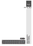
Profiler 14.1000 Frontseite
66
68
67
Abb. 1
Profiler 14.1000 Rückseite
Bedienungsanleitung Profiler 14.1000 © Zeck Audio
5
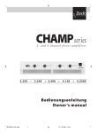
1. Eingangskanal
1
2
3
Der Profiler 14.1000 bietet zwei verschiedene Eingangskanäle.
Die Kanäle 1 - 6 sind mono ausgelegt (Abb. 2), die Kanäle 7 - 10 sind
stereo ausgelegt (Abb. 3). Es gibt
Unterschiede
bei
den
Anschlußmöglichkeiten und in der
Klangregelung.
6
7
8
9
10
11
12
13
14
15
16
17
18
6
1.1 Anschlüsse
Bei dem Mono-Eingangskanal kann
der Mikrofoneingang MIC (1) für
Mikrofone oder der LINE-Eingang
(2) für Line-Ausgänge von Instrumentenverstärker o.ä. benutzt werden. Die INSERT-Buchse (3) ermöglicht das Einschleifen von EffektGeräten pro Kanal. Diese StereoKlinkenbuchse liegt elektrisch nach
der Klangregelung. Die Spitze des
Stereo-Klinkensteckers führt das
Send-Signal, der Ring das ReturnSignal. Die INSERT-Buchse kann
auch als Ausgang (z.B. für
Mehrspurmaschinen) genutzt werden. In diesem Fall wird ein StereoKlinkenstecker verwendet, bei dem
Ring und Spitze miteinander verbunden sind. Dieser Ausgang bleibt
unbeeinflußt vom Kanal-Fader.
Bei dem Stereo-Eingangskanal sind
2 LINE-Buchsen für Stereoanwendung LEFT (4) und RIGHT (5) vorhanden. Hier können Keyboards oder
(Stereo-) Drumcomputer angeschlossen werden. Soll eine MonoQuelle angeschlossen werden, so ist
die obere Klinkenbuchse LEFT/
MONO (4) zu verwenden. Der Mikrofoneingang (1) ist wie bei den anderen Kanälen ein Mono-Eingang.
Als Hilfe für die Einstellung bietet
das Gerät die PFL-Funktion, die SIGNAL- und CLIP-LED im Eingangskanal, und die zweispaltige LED-Kette
im Masterteil.
Zur Einstellung darf nur der PFLSchalter (16,46,63) des einzustellenden Kanals gedrückt sein. Zur
Vergewisserung schauen Sie vor
dem Drücken des Kanal PFL-Schalters auf die PFL-LED (39) unterhalb
der zweispaltigen LED-Kette. Leuchtet diese LED, dann ist
irgendwo noch ein PFL-Schalter
(16,46,63) gedrückt, den Sie ausschalten müssen. Nach dem Drücken
des Kanal PFL-Schalters wird das Signal an der zweispaltigen LED-Kette
(38) angezeigt. Die PFL-LED (17) im
Eingangskanal und die PFL-LED (39)
unterhalb der LED-Kette leuchten,
das Eingangssignal ist im Kopfhörer
zu hören.
Beachten Sie, daß beispielsweise der
Sänger während dieser Einstellung
auch genau so laut singt, wie später während der Veranstaltung. Die
SIGNAL-LEDs (18) im Eingangskanal
zeigen durch ihr Aufleuchten an,
daß ein Signal am Eingang anliegt.
Beginnend vom linken Anschlag des
GAIN-Reglers (7) wird dieser langsam soweit nach rechts gedreht, bis
der durchschnittliche Pegel die LED
'0 dB' in der LED-Kette (38) zum
Leuchten bringt. Die LED '+3 dB'
darf nicht ständig leuchten! Diese
Prozedur muß für jeden Eingangskanal wiederholt werden !
1.3 Klangregelung
Die Monokanäle haben eine
3- Band Klangregelung mit paraDer LINE-Eingang ist bei den
metrischen Mitten. Der HIGH-RegMONO-Eingangskanälen symmeler (8) wirkt bei 12kHz mit ±14 dB,
trisch und bei den STEREOder LOW-Regler (11) arbeitet bei 60
Eingängen unsymmetrisch.
Hz mit ±14 dB. Die Frequenz (9) des
Mitten-EQ (10) ist einstellbar im Bereich von
1kHz - 6,3 kHz, mit ±14
1.2 Wichtig:
19
dB. Jeder Mono-Eingangskanal hat
Einstellung der Empfindlichkeit
einen schaltbaren LOW-CUT (6), der
unterhalb von 80 Hz die tiefen FreEs ist sehr wichtig, daß die Pegel der
quenzen mit 24 dB/Oct. unterdrückt.
einzelnen Kanäle optimal eingestellt
Damit kann z.B. der Trittschall bei
sind. Wenn auf die korrekte EinstelMikrofonen oder Pop-Geräusche bei
lung der Empfindlichkeit verzichtet
Abb.2
Gesang gedämpft werden. Der
wird, kann dies zu NebengeräuMonoLOW-CUT sollte grundsätzlich
schen wie Verzerren Rauschen
immer gedrückt sein, außer wenn
Eingangskanal
führen.
extrem tiefe Bässe benötigt werden.
Bedienungsanleitung Profiler 14.1000 © Zeck Audio
PROFILER 14.1000
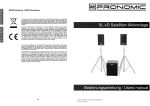
Die Stereokanäle haben eine
3- Band Klangregelung mit fest eingestellten Frequenzen:
1
HIGH(8) 10 kHz, ±14 dB;
MID (10) 3 kHz, ±14 dB;
LOW (11) 60 Hz, ±14 dB.
4
Die Klangregelung sollte normalerweise linear stehen (alle Regler auf
'0'). Sie sollte nur dann vorsichtig
benutzt werden, wenn bestimmte
Soundvorstellungen oder die örtliche Akustik dies erfordern. Es macht
keinen Sinn, alle Klangregler an den
Anschlag zu drehen, denn dies
würde in jedem Fall zu einer Verschlechterung des Klangbildes
führen.
5
7
8
Man sollte auf jeden Fall den Equalizer im Masterteil (42) zuerst einstellen (s.u.). Außerdem sollte nach
Einstellung des Kanal EQs der Pegel
mit PFL erneut überprüft werden.
10
1.4 Busregler
11
Der MON-Regler (12) legt einen beliebigen Anteil des Eingangs-signals
auf den Monitorweg. Der Monitorweg liegt 'pre-fade'. Am Monitorbus liegt auch dann das Signal an,
wenn der Kanalfader (19) auf 0
steht. Wenn man Stereo- Monitore
benutzen will, benutzt man am besten das Mastersignal am LINE OUT
Ausgang (22) über einen externen
Monitor-Verstärker.
12
13
14
Der AUX-Regler (13) legt einen
beliebigen Anteil des Eingangs-signals auf den Auxweg. Der Auxweg
ist im Masterteil PRE/POST schaltbar
(36), dadurch kann er als zweiter
Monitor- ('pre') oder
Effektweg ('post') benutzt werden.
Mit dem EFF-Regler (14) kann man
einen beliebigen Anteil des Eingangssignals auf den internen
Effekt geben. Der Effektweg liegt
'post-fade', es kommt das Signal nur
dann zum Effekteingang, wenn der
Kanalfader (19) nicht auf 0 steht.
15
16
17
18
19
Abb. 3
StereoEingangskanal
allerdings liegen die Stereo-Kanäle
grundsätzlich links und rechts, so
daß Panorama nur den einen oder
anderen Kanal ausblenden kann.
Die Kanallautstärke wird mit dem
Kanal-Fader (19) eingestellt. Bei Stereo-Kanälen werden Links und
Rechts gleichzeitig beeinflußt.
Der PFL-Schalter (Pre Fade Listening)
(16) ermöglicht das direkte Mithören des jeweiligen Kanalsignals
über den Kopfhörer. Der Kanalfader hat dabei keine Wirkung auf die
Lautstärke im Kopfhörer.
2. Mastersektion
(Abb. 4)
Mit den Masterfadern (49) wird die
Gesamtlautstärke des Geräts eingestellt. Der Gesamtpegel wird über
die zweispaltige LED-Zeile (38) angezeigt. Diese Anzeige ist an den
Endstufen-Eingangspegel gekoppelt.
2.1 Klangregelung
Die 5-Band Klangregelung (42)
dient zur Anpassung der Anlage an
die Raumakustik. Die Frequenzen liegen zur besseren Regelbarkeit anders als im Eingangskanal. Die
hohen Frequenzen sollten vorsichtig eingestellt werden, da bei zu vielen Höhen die Rauschanteile und
die Rückkopplungsgefahr steigen.
Für Klangkorrekturen der PA-Lautsprecher sollte die DIGITAL-SOUNDPROCESSOR-Funktion benutzt werden.
Grundsätzlich sollte zuerst die
Klangregelung im Masterkanal mit
Hilfe einer Test-CD o.ä. eingestellt
werden, und dann die Klangregelung in den Kanälen.
Der Regler PAN (Panorama) (15) verteilt das Eingangssignal anteilig auf
die Masterschienen links / rechts.
Steht Panorama in der Mittelstellung
(0), so wird das Eingangs- signal
gleich stark nach links und rechts verteilt. Bei Stereo-Anschluß eines Kanals ist Panorama auch in Funktion,
Bedienungsanleitung Profiler 14.1000 © Zeck Audio
7
20 21
22 23 24 25
28
27
26
33
32
31
29
30
34
35
2.2 Insert (20)
2.6 Aux-Weg
Die INSERT-Buchsen ermöglichen das
Einschleifen eines Effektgerätes vor
der Endstufe. Die Belegung der
STEREO-Buchsen ist gleich der des
Inserts im Eingangskanal (Spitze =
Send, Ring = Return, Masse). Diese Insertbuchsen ermöglichen auch den
einfachen Anschluß des aktiven Subwoofers DCA 501L, mit diesem entsteht eine 2-weg Aktivanlage.
Der AUX-Weg kann wahlweise als zusätzlicher Monitor- oder Effektweg
benutzt werden. Hierzu ist er
PRE/POST schaltbar. PRE/POST gibt die
Anordnung des AUX-Wegs bezogen
auf den Kanalfader an. PRE heißt vor
und POST heißt nach, der AUX-Weg
ist also entweder vor oder nach dem
Fader angeordnet.
Um den AUX-Weg als Monitorweg zu
konfigurieren, schaltet man den
PRE/POST - Schalter (36) auf die Stellung 'PRE', damit die Lautstärke auf
dem Monitor von der Stellung des Kanalfaders unabhängig ist. Der AUX
SEND Regler (33) ist dann für den Gesamt-Monitorpegel zuständig.
Um den AUX-Weg als Effektweg zu
konfigurieren, muß der PRE/POST Schalter (36) auf der Stellung 'POST'
stehen. Der Eingang des Effektgerätes wird an die AUX SEND Buchse (28)
angeschlossen und mit dem AUX
SEND Regler (33) eingepegelt. Die
Buchsen AUX RETURN (23) sind dann
der Effektreturn, hier wird der Ausgang des Effektgerätes angeschlossen. Falls der Ausgang Mono ist, dann
brauchen Sie nur die obere ReturnBuchse ’L/MONO’ benutzen. Die Lautstärke des Effekts auf den Masterkanälen ist mit dem AUX RET.- Regler (34) einzustellen.
Der AUX RETURN kann auch als LINEIN benutzt werden, beispielsweise um
von einem Submixer das Signal einzuspeisen.
37 2.3 Amp In (21)
36
38
40
39
41
55
43
56
57
Der Eingang AMP IN dient zur
Ansteuerung der eingebauten Endstufen. Bei Belegung dieser Buchsen
wird die Verbindung zwischen Mischpultsektion und Endstuensektion automatisch aufgetrennt. Wenn eine
stärkere Anlage benötigt wird, können die LINE-OUT-Buchsen (22) als
Masterausgänge benutzt werden, um
stärkere externe Endstufen anzusteuern. Die eingebauten Endstufen können dann als Monitor-Endstufen benutzt werden, indem der MONITORSEND-Ausgang (27) mit einem YKabel mit dem AMP-IN-Eingang (21)
verbunden wird. An den AMP-IN-Eingang kann auch der Ausgang eines
externen Mischpults angeschlossen
werden.
58
59
60
61
63
62
64
65
52 2.4 Mono Out (26)
42
44
45
46
47
48
50
Am MONO-OUT - Ausgang liegt das
53 zusammengemischte Signal von
51 linkem und rechtem Masterkanal an.
49
Die Lautstärke ist abhängig von der
54 Stellung der Masterfader und kann
Abb. 4
Profiler 14.1000
Mastersektion
mit dem MONO-OUT - Regler (31) eingestellt werden. An der MONO- OUT
- Buchse können Subwoofer (Aktive,
Passive über separate Endstufen), oder
eine separate Endstufe zur Ansteuerung von Boxen in Nebenräumen angeschlossen werden.
2.5 Line Out
Der LINE-OUT Ausgang ist vor den
Masterfadern (49) und nach der
Klangregelung angeordnet. Die Lautstärke ist unabhängig von der Stellung der Masterfader und kann mit
dem LINE-OUT Regler (32) eingestellt
werden.
8
Bedienungsanleitung Profiler 14.1000 © Zeck Audio
PROFILER 14.1000
2.7 Effect Send (29)
An der EFFECT-SEND - Buchse liegt
dasselbe Signal an wie am Eingang
des internen Effektgerätes. Wie beim
internen Effekt auch, wird die Lautstärke des Einzelkanals im
Effektweg mit dem EFF.-Regler (14) in
den Eingangskanälen eingestellt.
Wenn das interne Effektgerät abgeschaltet werden soll, muß entweder
der Effekt ausgeschaltet sein (62)
oder/und der EFFECT-Fader (51) auf
0 stehen.
Der Ausgang des externen Effektgerätes wird mit dem Eingang AUX
RET. (23) verbunden. Wenn das externe Effektgerät mono ist, dann muß
nur der obere Eingang AUX RET.
L/MONO benutzt werden. Die Lautstärke des externen Effekts auf den
Masterkanälen ist mit dem AUX RET.Regler (34) einzustellen.
2.8 Tape Anschluß (24/25)
Ein Tape-Deck oder DAT-Recorder
kann an diesen Cinch-Buchsen angeschlossen werden. Der CD/TAPE IN Eingang (24) kann auch von einem
CD-Player belegt werden. Die Lautstärke des Eingangs wird nur mit dem
CD/TAPE IN - Regler (35) eingestellt,
die MASTER Fader (49) haben keinen
Einfluß auf die Lautstärke! Das Signal
des TAPE IN - Eingangs wird durch
den STAND BY - Schalter (54) nicht abgeschaltet und ist somit für Pausenmusik nutzbar. Das Signal ist nicht
über Kopfhörer abzuhören und wird
nicht im VU-Meter angezeigt. Die Masterklangregelung (42) hat keinen Einfluß auf den Tape Eingang.
Der Pegel des RECORD OUT - Ausgangs (25) ist unabhängig von den MASTER-Fadern (49) und nicht regelbar.
Die Master-Klangregelung (42) beeinflußt auch das Signal des RECORD
OUT.
Die Phantom-Spannung liegt an den
Pins 2 und 3 an. Selbstverständlich
können weiterhin auch dynamische
Mikrofone angeschlossen werden. Allerdings muß dann zum Schutz der dynamischen Mikrofone eine Vorsichtsmaßnahme
getroffen
werden:
Während des Verkabelns muß die
Phantomspeisung ausgeschaltet sein!
Genauso darf beim Abschalten die
Phantomspeisung nicht eingeschaltet
sein.
2.10 DIGITAL SOUND PROCESSOR
Mit dem Schalter DIGITAL SOUND
PROCESSOR (41) wird der eingebaute
Prozessor aktiviert. Es dauert nach
dem Einschalten einige Sekunden, bis
der Prozessor aktiv wird. Die nach dieser Zeit dann hörbare Klangverbesserung wird optisch durch Aufleuchten
der ACTIVE-LED angezeigt.
Während des Betriebs wird über die
Helligkeit dieser LED der Arbeitszustand des SOUND PROCESSOR angezeigt. Mit zunehmender Lautstärke
werden Basskompensation und
Höhenkorrektur gleitend zurückgeregelt, entsprechend verliert dann die
LED an Helligkeit. Bei Maximalleistung ist die Prozessorregelung auf
den Linearwert zurückgestellt und der
dynamische Limiter geht in Funktion.
Die DIGITAL SOUND PROCESSORSchaltung ist technisch so realisiert, daß
die Klangkorrektur im hörbaren Bereich zwischen 30 und 80 Hz vollzogen wird. Tiefere Frequenzen werden
nicht beeinflußt, um unnötige Belastungen im nicht hörbaren Bereich zu
vermeiden. Je Kanal ist eine doppelte
Überwachungs- und Korrekturregelung vorhanden, bei welcher intelligente Filter aus der Digital- und Analogschaltungstechnik zur Anwendung
kommen. Das Ausgangssignal zur Box
wird ständig gemessen, digital umgesetzt und über digitale Regelkreise behandelt. Die gesamten Regel2.9 Phantomspeisung
kreise arbeiten extrem schnell und
sauber, die Gefahr einer thermischen
Die Eingangskanäle 1 - 6 werden mit Überlastung des Lautsprechers wird
Phantomspeisung versorgt, wenn der minimiert.
Schalter PHANTOM POWER (37) gedrückt ist und die Kontroll - LED aufleuchtet. Mit der Phantomspeisung
können professionelle KondensatorMikrofone mit der notwendigen
Spannung versorgt werden, bei einigen Mikrofonen kann hierdurch auf
die Batterie verzichtet werden.
Bedienungsanleitung Profiler 14.1000 © Zeck Audio
9
2.11 Limiter
2.15 Netzschalter
Der Limiter ist nicht schaltbar und
aktiviert sich pro Kanal automatisch, wenn er das Auftreten nicht
linearer Betriebszustände wie z.B.
Übersteuerung oder falsche Impedanz erkennt. Der Limiter regelt
entsprechend das Eingangssignal
nach einem akustisch optimierten
Algorithmus aus. Diese Regelung ist
so aufgebaut, daß keine DynamikVerluste entstehen.
Das Netzkabel ist an die Netzbuchse
(67) auf der Rückseite des Gerätes
angeschlossen. Hier befindet sich
ebenfalls der Netzschalter (66), mit
dem das Gerät an- und ausgeschaltet wird. In der Netzbuchse ist der
Sicherungshalter integriert. Es dürfen nur Sicherungen eingesetzt
werden, deren Nennwerte dem auf
dem Gerät aufgedruckten Wert
entsprechen!
2.12 Lautsprecherausgang
3. Monitorweg
An den Speakonbuchsen (68) werden
die Lautsprecherboxen angeschlossen. Beachten Sie, daß nach dem
Einstecken der Speakonstecker in
die Buchsen die Stecker noch nach
rechts gedreht werden müssen, um
den elektrischen Kontakt herzustellen. Bei den Speakonbuchsen sind
die Pins 1+ (heiß) und 1- (Masse)
belegt. Achten Sie darauf, daß die
Gesamtimpedanz pro Kanal von 4
Ohm (entspricht zwei 8 Ohm Boxen) nicht unterschritten wird.
Sie können zwar niedrigere Gesamtimpedanzen anschließen, jedoch
ist dann ein Überhitzen der Endstufen möglich. In diesem Fall würde
der Temperaturschutz eingreifen
und die Endstufen abschalten.
Der MON-Fader (50) legt die Summenlautstärke der Monitorwege
fest. An der Buchse MONITOR-SEND
(27) wird die externe Monitorendstufe oder ein aktiver Monitor (z.B.
Zeck MS15/3 aktiv) angeschlossen.
Die Taste 'L/R TO MON' (44) legt
das Mastersignal LEFT/RIGHT auf
den Monitor. Die MON-Regler (12)
in den Eingangskanälen haben
dann keinen Einfluß mehr auf das
Monitorsignal.
Mit der 3-Band Klangregelung läßt
sich das Monitorsignal auch klanglich auf die Gegebenheiten der
Bühne einstellen. Mit den parametrischen Mitten lassen sich gezielt
Rückkopplungen minimieren.Der
Regler ‘Eff TO MON’ (45) mischt das
Effektsignal dem Monitorweg zu.
Mit den Signal- und Clip-LEDs kann
der Pegel des Monitorsignals kontrolliert werden. Wenn die CLIP-LED
(47) aufleuchtet, dann müssen die
MON-Regler in den Eingangskanälen etwas zurückgenommen
werden. Der dadurch entstehende
Lautstärkeverlust kann dann durch
den MONITOR-Fader ausgeglichen
werden.
Mit dem PFL-Schalter (46) kann das
Monitorsignal auf den Kopfhörer
geschaltet werden.
2.13 Kopfhörer
Ein Stereo-Kopfhörer kann über die
Stereoklinkenbuchse PHONES (52)
angeschlossen werden, die Lautstärke wird mit dem PHONES
VOLUME - Regler (53) eingestellt.
Am Kopfhörer liegt entweder das
Mastersignal in Stereo an oder bei
mindestens einem gedrücktem PFLSchalter das entsprechende PFL-Signal
in Mono.
2.14 Standby
4. Effektsektion
Das Gerät ist mit einem digitalen
Effektgerät mit 99 Programmen
ausgestattet. Der Effekt wird mit
der Taste 'EFFECT ON' (62) ein- und
ausgeschaltet. Bei ausgeschaltetem
Effekt blinkt die Programmnummer
(55), bei eingeschaltetem Effekt
leuchtet die Nummer ständig.
Mit dem Fader 'EFFECT' (51) wird
das Effektsignal dem Masterkanal
zugemischt.
Mit dem PFL-Schalter (63) wird das
Effektsignal auf den Kopfhörer
geschaltet.
4.1 Wichtig:
Richtige Aussteuerung
Das richtige interne Aussteuern des
Effektgerätes ist von sehr großer
Bedeutung bezüglich des Rauschpegels. Eine SIGNAL- und eine CLIPLED (64) erleichtern das richtige
Aussteuern mit den EFF-Reglern in
den Eingangskanälen. Richtig ausgesteuert ist das Effektgerät, wenn
die SIGNAL-LED (65) noch immer
und die CLIP LED gerade noch nicht
leuchten. Die Lautstärke des Effekts
auf dem Masterkanal wird dann mit
dem EFFECT-Fader (51) eingestellt.
4.2 Effekt wählen
Ein Effekt wird aufgerufen, indem
mit dem Drehknopf SELECT (56) die
gewünschte Programmnummer
eingestellt wird. Die eingestellte
Programmnummer wird dann mit
dem Drücken der Taste ENTER (57)
aktiviert. Solange die Programmnummer nicht aktiviert ist, blinken
die zwei Punkte in der Anzeige (55).
Wenn ein Programm eingestellt ist,
das auf einer Presettaste (58-61)
gespeichert ist, dann wird die
Presetnummer (P1 bis P4)
angezeigt (siehe Abb. 4).
Mit dem Schalter STAND BY (54)
wird das Mastersignal LEFT/RIGHT
geräuschlos ein- und ausgeschaltet.
In Stand by - Funktion leuchten die
roten LEDs (40) im Master - VU. Der
Eingang CD/TAPE IN wird durch diesen Schalter nicht abgeschaltet, so
ist die Übertragung von Pausenmusik bei abgeschalteten Mikrofonen
möglich.
10
Bedienungsanleitung Profiler 14.1000 © Zeck Audio
PROFILER 14.1000
1.
2.
ENTER
Preset speichern
3.
ENTER
DOWN
UP
SELECT
+
PRESET
1, 2, 3 oder 4
Abb. 5
Preset programmieren
Die gewünschte Effektnummer
muß mit dem Drehregler SELECT
(56) eingestellt werden. Zum
Speichern müssen die Tasten Enter
(57) und die entsprechende Presettaste in dieser Reihenfolge nacheinander gedrückt und gedrückt
gehalten werden. Nach dem
Drücken der Presettaste ist das
Programm dauerhaft gespeichert.
4.4 Fußschalter - TYP
4.3 Preset (58-61)
Das Gerät bietet die Möglichkeit,
die vier am meisten genutzten
Effektprogramme auf PRESETTasten (58-61) zu speichern. So ist
der blitzschnelle Zugriff auf die
Lieblingsprogramme ganz einfach
machbar. Das Gerät bietet noch
ein zusätzliches Feature:
Die vier PRESETS sind auch mit
dem Fußschalter durchsteppbar,
so daß während der Show das
Effektprogramm mit dem Fuß
verändert werden kann.
Die Einstellungen der Effektsektion
(Programmnummer, Presets,
Fußschaltertyp, Fußschalterfunktion,
Effekt an/aus) bleiben auch nach
dem Abschalten des Geräts für einige Jahre gespeichert.
Preset aufrufen
Zum Aufruf des Presetprogramms
muß die entsprechende PRESETTaste (58-61) gedrückt werden. Es
wird dann der Preset angezeigt
(P1, P2, P3 oder P4). Um die hinterlegte Effektprogrammnummer
anzuzeigen, muß die PRESET-Taste
einige Sekunden lang gedrückt
bleiben. Die Anzeige (55) wechselt
dann zur Programmnummer.
Wenn die PRESET-Taste losgelassen wird, wechselt die Anzeige
wieder zur Presetnummer.
Um wieder auf das mit dem Drehregler SELECT (56) eingestellte
Programm zu wechseln, muß die
ENTER-Taste (57) gedrückt werden.
Somit stehen im Prinzip 5 Presets
zur Verfügung: die 4 Presets und
das mit dem Drehregler Select
gewählte Programm.
An der Klinkenbuchse FOOTSWITCH
(30) kann ein Fußschalter angeschlossen werden. Es gibt Fußschalter, die als Taster oder als
Schalter ausgeführt sind. Beide
Fußschaltertypen können an Ihrem
Gerät angeschlossen werden. Für
die korrekte Funktionsweise muß
der Fußschaltertyp programmiert
werden. Um den Fußschaltertyp
'TASTER' zu programmieren, müssen die Tasten ENTER (57), PRESET
3 (60) und ON (62) in dieser Reihenfolge nacheinander gedrückt
und gedrückt gehalten werden.
Nach dem Drücken der ON-Taste
ist die Funktion ‘TYP= TASTER’
dauerhaft gespeichert.
Der Fußschaltertyp 'SCHALTER' ist
ab Werk gespeichert. Um diesen
Typ zu programmieren, müssen
die Tasten ENTER (57), PRESET 4
(61) und ON (62) in dieser Reihenfolge nacheinander gedrückt und
gedrückt gehalten werden. Nach
1.
ENTER
2.
3.
ENTER
+
PRESET
1, 2, 3 oder 4
PRESET
1, 2, 3 oder 4
+
EFFECT
ON / OFF
Abb. 6
4.5 Fußschalter - FUNKTIONEN
Es stehen zwei Funktion zur Wahl.
Die erste, ab Werk eingestellte
Funktion ist das Ein- und Ausschalten
des Effekts. Dabei spielt die Schalterstellung des ON-Schalters keine
Rolle. Zum Programmieren dieser
Funktion müssen die Tasten ENTER
(57), PRESET 1 (58) und ON (62) in
dieser Reihenfolge nacheinander
gedrückt und gedrückt gehalten
werden. Nach dem Drücken der
ON-Taste ist die Funktion ‘EIN/
AUSSCHALTEN’ dauerhaft gespeichert.
Die zweite Funktion ist das
Durchsteppen der vier Presets.
Nach jedem Betätigen des Fußschalters wird der jeweils nächste
Preset aufgerufen. Um diese
Durchstepp-Funktion zu programmieren, müssen die Tasten ENTER
(57), PRESET 2 (59) und ON (62) in
dieser Reihenfolge nacheinander
gedrückt und gedrückt gehalten
werden. Nach dem Drücken der
ON-Taste ist die Funktion ‘Durchsteppen’ dauerhaft gespeichert
(siehe Abb. 6).
5. Soundbeschreibungen
Multi-Effects-Processor
Gruppe Hall,
Programme 1 - 16
ENTER
+
dem Drücken der ON-Taste ist die
Funktion ‘TYP=SCHALTER’ dauerhaft gespeichert (siehe Abb. 6).
Programmieren des
Fußschalters
Preset 1 für ‘ON/OFF’-Funktion
Preset 2 für ‘Durchstepp’-Funktion
Preset 3: Fußschalter = Taster
Preset 4: Fußschalter = Schalter
Die Halleffekte simulieren das
Nachklangverhalten verschieden
großer Hallen. Aufgrund des neutralen Klangbilds ist dieser Effekt
für alle Instrumente und Gesang
universell einsetzbar. Es stehen
Nachhallzeiten von 0.5s bis 15s (!)
zur Verfügung. Bei den längeren
Hallzeiten wird mit einem Predelay gearbeitet, um einen noch
natürlicheren Effekt zu erzielen.
Mit zu langen Nachhallzeiten über
3s sollte man vorsichtig umgehen,
um verwaschene Klangbilder zu
vermeiden. Sie eignen sich hauptsächlich für sparsame musikalische
Arrangements.
Bedienungsanleitung Profiler 14.1000 © Zeck Audio
11
Gruppe Room,
Programme 17 - 32
Gruppe Reverse,
Programme 57 - 60
Gruppe Ping Pong Delay,
Programme 80 - 85
Diese Effekte bilden das akustische Verhalten verschieden großer
Räume nach. Wichtig für die
klangliche Wirkung eines Raumes
sind vor allem die Reflexionen, die
von seinen Wänden ausgehen. Die
'Room' - Effekte eignen sich hervorragend dazu, alle Arten von
Percussion und Schlagzeug lebendiger klingenzulassen. Auch Instrumentalsoli wie Saxophon oder
E-Gitarren werden durch diese Effekte angereichert.
Bei einem Reverse-Hall wird der
natürliche Hallverlauf, wie er etwa
in der ersten Effektgruppe 'Hall'
erscheint, zeitlich gespiegelt wiedergegeben. Der wiedergegebene
Ton wird rückwärts 'abgespielt',
schwillt also langsam an, um dann
abrupt abzubrechen. Dieser Effekt
klingt noch synthetischer als die
'Gate'-Programme. Man kann mit
diesem Effekt den Klang rückwärts abgespielter Instrumente
nachahmen, was ab und zu bei
Schlagzeugen und Gitarren für
einen psychedelischen Effekt eingesetzt wird.
Die Echos werden bei diesen
Effekten wie ein Tischtennisball
zwischen den beiden Kanälen hin
und her 'geworfen', was besonders am Ende eines Stückes ein
schöner Effekt ist.
Hallplatten wurden in früheren
Zeiten zur Erzeugung hochwertiger Nachhalleffekte eingesetzt.
Auch die in Gitarrenverstärkern
oft vorhandenen Hallspiralen
gehören in diese Gruppe der
mechanischen Nachhallerzeugung.
Obwohl sie im digitalen Zeitalter
etwas aus der Mode gekommen
sind, schwören noch viele Benutzer auf den 'Sound', den diese
Geräte produzierten. Die Effekte
eignen sich besonders für Tasteninstrumente und Gitarre, aber
auch für Gesang.
Gruppe Hall + Delay,
Programme 61 - 69
Gruppe Special Effects,
Programme 94 - 99
Diese Effekte haben verschiedene
Nachhallzeiten und ein darübergelegtes Echo. Der Stereo-Effekt
wird durch zeitliche Versetzung
der links und rechts gelegenen
Echos erzeugt, was dem Gesamtklang eine angenehme Räumlichkeit verleiht. Ein guter AllroundEffekt.
Ein Sammelsurium verschiedener
nützlicher Effekte. Besonders erwähnenswert: Programm 94 für
gallopierende Echos ala 'Shadows',
oder Nr, 95 und 96 für Rockabilly.
Die Programme 97-99 erzeugen
Verdopplungs-Effekte. Neben
einem Nachhall ist hier noch ein
Delay mit kurzen Zeiten überlagert. Dadurch entsteht das Gefühl,
als würden zwei Personen gleichzeitig singen. Mit diesem Effekt
klingen Gesang und Instrumente
voller.
Gruppe Gate,
Programme 49 - 56
Diese Gruppe beinhaltet Hallprogramme, die erst nach einer längeren Zeit 'starten' und sich somit
weniger mit dem Originalsignal
vermischen.
Gruppe Plate,
Programme 33 - 48
Bei diesen Effekten klingt der
Nachhall nicht langsam aus, sondern wird nach einer bestimmten
Zeit abgeschnitten. Da ein solches
Nachhallverhalten in der Natur
nicht vorkommt, wirkt dieser
Effekt sehr technisch. Percussion
und Schlagzeug bekommen einen
zeitgemäßen Sound, auch Bläserinstrumente werden wirkungsvoll
in Szene gesetzt.
12
Gruppe Hall m. langem Pre-Delay,
Programme 70 - 73
Gruppe Stereo Echos,
Programme 86 - 93
Die Echos entsprechen den Delays,
nur entstehen hier mehrere Echos
mit abklingender Intensität hintereinander.
Gruppe Stereo-Delays,
Programme 74 - 79
Hier ist die ganze Palette vom
Rock'n Roll Echo bis zu ultralangen
Delays vorhanden. Der StereoEffekt wird durch etwas verschieden lange Delay-Zeiten für links
und rechts erzeugt.
Bei der Auswahl von Delay-Effekten sollte man darauf achten, daß
die Echozeiten ungefähr mit dem
Tempo der Musik Übereinstimmen. Wenn die Echos etwas
schneller sind als die Musik, dann
treibt das Echo den Rhythmus
nach vorn. Langsamere Echos entspannen das Tempogefühl.
Bedienungsanleitung Profiler 14.1000 © Zeck Audio
PROFILER 14.1000
6. Störungsbehebung
Problem
Mögliche Ursache
Tiefe Bässe sind nicht zu hören.
Low Cut (6) im Eingangskanal wurde gedrückt
Beim Einschalten der Phantomspeisung
(37) ensteht ein lautes Brummen.
Wahrscheinlich ist ein Keyboard o.ä. unsymmetrisch
an einen XLR-Eingang (1) angeschlossen.
Abhilfe:
entweder LINE IN Eingang (2 bzw 4/5) benutzen
oder Signal mit DI-Box symmetrieren.
Beim Einschalten der Phantomspeisung (37).
gibt es in einem dynamischen Mikrofon
einen hörbaren 'Klick'.
Mikrofonkabel falsch gelötet. Das Mikrofonkabel
muß symmetrisch aufgebaut sein.
Kein Signal an Aux Send Buchse (28) trotz
aufgedrehtem Aux Regler (13) im Kanal.
Aux Send Regler (33) im Master nicht aufgedreht.
Aux-Weg ist 'Post' (36) geschaltet und der Kanalfader (49) nicht hochgezogen.
Clip-LED im Eingangs-/Monitor-/Effektkanal
leuchtet ständig, obwohl kein Signal anliegt.
PFL-Taste ist gedrückt.
Die LED-Zeile (38) zeigt nicht das
Mastersignal an
Irgendwo ist eine PFL-Taste gedrückt.
Der Mon-Regler (12) im Eingangskanal hat
keine Wirkung auf die Lautstärke im Monitorweg.
L/R - Taste (44) im Monitorkanal ist gedrückt. Nur das
Mastersignal wird dann auf den Monitorkanal geschaltet.
Internes Effektgerät rauscht stark.
Effekt zu niedrig ausgesteuert. Effektregler in
den Eingangskanälen aufdrehen, bis die Clip-LED
(64) im Effektkanal gerade noch nicht leuchtet.
Internes Effektgerät verzerrt.
Effekt zu hoch ausgesteuert. Effektregler (14) in
den Eingangskanälen zurückdrehen, bis die ClipLED (17) im Effektkanal gerade nicht mehr leuchtet.
Effektprogramm läßt sich nicht mehr
einstellen, die Tastatur ist 'tot'.
Select-Regler (56) steht nicht exakt auf einer
Rastung.
Fußschalter funktioniert nicht richtig.
Falscher Fußschaltertyp eingestellt. Gerät
aus- und wieder einschalten, Fußschaltertyp richtig
programieren
Falscher Fußschaltertyp angeschlossen.
Nur Fußschalter (oder -taster) ohne Vorwiderstände,
ohne Anzeigenleuchten und ohne eigene
Stromversorgung benutzen.
Kein Ton zu hören, obwohl
die LED-Zeile (38) etwas anzeigt.
Speakon-Lautsprecherstecker nicht richtig eingesteckt.
Nach dem Einstecken unbedingt nach rechts drehen,
um den elektrischen Kontakt herzustellen.
Gerät wird sehr heiß und
die Endstufen schalten ab.
Gesamtimpedanz der angeschlossenen Boxen pro
Kanal ist zu niedrig (4 Ohm Minimum!).
Psychoakustischer Effekt ist angeschlossen, der unhörbar
tiefe Frequenzen erzeugt und die Boxen und Endstufen
überlastet. Abhilfe: Lowcut / EQ einschleifen.
Bedienungsanleitung Profiler 14.1000 © Zeck Audio
13
Dear customer,
thank you for purchasing the ZECK Profiler 14.1000 mixing
console. This fine unit has been designed to inspire your
creativity, bring you success and - not least - lots of fun.
Please read the following instructions carefully to make
sure that all the functions and possibilities of the Profiler
become quickly available to you.
Your Zeck team
Safety instructions
1. Read instructions - Dry-read all safety and operation instructions at least once before starting to work
with the Profiler 14.1000.
2. Heed warnings - All warnings given on the Profiler 14.1000 or inside this manual should be strictly followed.
3. Water and moisture - The Profiler 14.1000 should never be operated near water, e.g. near a
washbowl, bathtub, kitchen sink, laundry tub, swimming pool or in a wet basement.
4. Heat - Keep the Profiler 14.1000 away from devices that produce heat, e.g. radiators.
5. Object and liquid entry - Do not allow solid objects or liquids to fall into or spill over the Profiler 14.1000.
6. Power sources - For protection against electric shock, use only power connectors for the Profiler 14.1000
that are absolutely proof against protruding contacts.
7. Grounding / protective earth - The Profiler 14.1000 must always be operated with effective
protective earth. Never manipulate or defeat the protective earth means of the unit or power supply.
8. Power cord protection - Power supply cords for the Profiler 14.1000 should be routed so that the danger
of pinching by objects, walking upon or stumbling over is excluded. Particular care should be
taken to keep away mechanical strain from the power cable entry and the power plugs.
9. Servicing - The user should not attempt to open or service the Profiler 14.1000. For maintenance
and servicing, always refer to qualified repair personnel.
10. Keep instructions - This instruction manual should be retained for future reference.
14
Owner`s manual Profiler 14.1000 © Zeck Audio
PROFILER 14.1000
General description (numbers refer to illustrations on following pages)
1
XLR input connector
38
Master LED chain display
2
Line In (monaural channel)
39
PFL control LED (Master)
3
Insert jack (monaural channel)
40
Standby LED
4
Line In Left/Mono (stereo channel)
41
Digital Sound Processor button
5
Line In Right (stereo channel)
42
5-band Master EQ
6
Low Cut filter
43
3-band Monitor EQ
7
Gain control
44
‘L/R to Monitor‘ button
8
High EQ control
45
‘Effect to Monitor‘ control
9
Mid EQ control
46
Monitor PFL switch
10
Mid EQ control
47
Monitor Clip LED
11
Low EQ control
48
Monitor Signal LED
12
Mon control (input channel)
49
Master faders
13
Aux control (input channel)
50
Monitor fader
14
Effect control (input channel)
51
Effect fader
15
Pan control
52
Phones jack
16
PFL button (input channel)
53
Phones Volume control knob
17
Clip/PFL LED (input channel)
54
Standby switch
18
Signal LED (input channel)
55
Effect program number display
19
Channel fader
56
Effect selector
20
Insert jacks (master channel)
57
Effect Enter button
21
Amp In jacks
58
Effect Preset 1 button
22
Line Out jacks
59
Effect Preset 2 button
23
Aux Return jacks
60
Effect Preset 3 button
24
CD/Tape In phon jacks
61
Effect Preset 4 button
25
Record Out phon jacks
62
Effect On button
26
Mono Out jack
63
Effect PFL switch
27
Monitor Send jacks
64
Effect Clip LED
28
Aux Send jack
65
Effect Signal LED
29
Effect Send jack
66
Power switch
30
Effect footswitch jack
67
Mains connector
31
Mono Out control
68
Speaker connectors
32
Line Out control
33
Aux Send control
34
Aux Return control
35
Tape In control knob
36
Pre/Post button
37
Phantom Power switch
Owner`s manual Profiler 14.1000 © Zeck Audio
15
Input channels
stereo
Input channels
mono
Master-/ Monitor-/
Effekt section
Profiler 14.1000
front panel
66
68
67
Fig. 1
Profiler 14.1000
back panel
16
Owner`s manual Profiler 14.1000 © Zeck Audio
PROFILER 14.1000
1. Input channels
1
The Profiler 14.1000 offers two
types of input channels:
Channels 7-10 have full stereo
operation capability while the remaining channels 1-6 are monaural.
There are some distinct differences
regarding the connectors and
equalization, which will be
described in the following chapters.
2
3
6
7
1.1 Input connectors
Each monaural channel (Fig. 2) has
one balanced XLR input (1) for
microphones (MIC) and one balanced
1/4" phone jack (2) for monaural
line-level signals (LINE IN). The stereo
channels have one balanced XLR
input connector (1) for microphones plus two unbalanced 1/4"
phone jack inputs (4/5) for stereo
signals, e.g. from keyboards or
drum computers, assigned to the
left and right channel (LEFT /
RIGHT LINE IN).
8
9
10
11
Any stereo channel can also be
used as a monaural channel by
using the XLR input (1) or by using
only the LEFT/MONO input phone
jack (4). In this case, the signal will
be send to both left and right
channels, depending on the PAN
(15) setting (see 1.4).
12
13
The monaural channels are additionally equipped with a break-type
INSERT jack (3) for direct connection
of external effect devices. This stereo
jack is electronically located after
the EQ section and has the Send
signal on the tip and the Return
signal on the ring of a stereo phone
plug. The INSERT jack can also be
used as a direct (pre-fade) channel
output, e.g. for multi-track recording,
by simply soldering the tip and
ring contacts of a stereo phone
plug together.
14
15
16
17
18
19
Fig. 2
MonoInput channel
1.2 A must-read:
proper input gain setting
For getting a clean and noise-free
sound, it is extremely important to
carefully adjust the GAIN control
(7) of every channel to the incoming
signal. It is not seldom that sound
problems with PA systems can be
traced back to incorrect input gain
settings.
The Profiler 14.1000 provides
various help functions for getting
the right input gain setting: the
built-in PFL function, SIGNAL and
CLIP LEDs on every input channel
and the two-row LED chain in the
master section.
Before depressing a channel's PFL
button (16) for input signal gain
adjustments, it is always a good
idea to check the PFL control LED
(39) beneath the master LED chain.
If it is lit, the PFL function has been
previously activated for another
channel and should be disengaged
there before attempting to adjust
the new channel.
If the PFL function is activated, the
input gain of the channel is shown
at the two-row master LED chain
(38). At the same time, the channel
input signal is also sent to the
PHONES output (52) for simultaneous ear-control.
One good advice: when making
input gain adjustments, you never
exactly know what's going to happen level-wise. To avoid embarrassing uncontrolled signals in your
PA, keep all fader controllers
down for now. Your ears and
speakers will thank you!
For quickly finding the right input
gain adjustment, first rotate the
GAIN control pot (7) fully counterclockwise. Ask the musician on the
other side of the cable to produce
an average-level signal, just like
he/she would during the show.
The green SIGNAL LED (18) shows
that the signal is now at the channel
input, waiting to become adjusted.
Slowly rotate the GAIN control
clockwise until the '0dB' LED in the
master LED chain becomes continuously lit, but not the '+3dB' LED!
Repeat this procedure for the
remaining channels.
Owner`s manual Profiler 14.1000 © Zeck Audio
17
1
4
5
7
8
10
11
1.4 Other channel controls
All monaural channels have an
active 3-band equalizing section
with parametric midrange. The
HIGH (Treble) control (8) works at
10 kHz with ±14dB boost/cut, the
LOW (Bass) (11) control works at
60 Hz, also with ±14 dB. The mid
frequency can be swept from 1 kHz
to 6.3 kHz with the FREQ knob (9),
MID cut/boost range (10) is also
±14 dB. Each monaural channel is
also equipped with a switchable
LOW CUT filter (6) for the XLR microphone input. This 12 dB/oct. filter
eliminates all frequencies below
80 Hz, which consist mostly of lowfrequency noise. Unless ultra-deep
low frequencies are wanted (most
unlikely for a microphone input), it
should always be kept engaged.
The stereo channels have a 3-band
equalization section with fixed
midrange frequencies:
The MON control knob (12) determines the proportion of the channel signal in the monaural monitor
signal. Keep in mind that the monitor
signal is taken from the channel
signal before it meets the fader
(pre-fade). This means that a
channel might be audible in the
monitor, even when its fader is at
zero - a common source of confusion!
If you have stereo monitors and
want a duplicate of your stereo
front PA signal in them, use the
LINE OUT output with an external
amplifier (see 2.7).
HIGH (8) 10 kHz, ±14dB
MID (10) 3 kHz, ±14dB
LOW (11) 60 Hz, ±14dB
Use the EFF (14) control to send a
variable portion of the channel
signal to the internal effect unit.
This control is post-fade, so that no
effect signal is produced for this
channel when its fader is down.
There's a golden rule for the use
of equalizers: try to get along
with as little as possible! Don't try
to use the EQ as an antidote
against poor microphones or
cheap PA speakers - you are likely
to end up with the EQ controls all
the way up and still get a muddy
sound. Use the channel EQ section
with thought to give the individual
instruments a happy place to live
within the overall sound.
12
13
14
One other advice: do not touch
the channel EQs (that means set
them to center position) before
you have calibrated the master EQ
to the room acoustics (see below).
This is also a good moment to decide, whether you want to use the
built-in DIGITAL SOUND PROCESSOR
(see below for explanation).
15
16
17
18
As the channel EQ affects the
input gain readings of the PFL
function, it is always a good idea
to re-check the channel gain after
setting the EQ to avoid clipping.
19
Fig. 3
StereoInput channel
18
1.3 Channel equalization
The AUX control knob (13) feeds
the channel signal to the Aux bus.
It can be switched for PRE or POST
fade function (36) in the master
section, allowing to use it as an
additional monitor path (pre) or as
an effect loop (post).
The PAN control (15) makes the
channel signal travel between left
and right, making it possible to
place the signal somewhere in the
stereo image. When in center
position, the channel signal is send
to the left and right side of the
master section in equal proportions.
If a channel is used stereo, the two
channel signals are stuck with their
assigned sides and cannot be
moved inside the stereo image. In
this case, the PAN control works
like the usual 'Balance' control on
your home stereo equipment.
The channel fader (19) provides
the final level control for the channel.
On stereo channels, both left and
right signals are controlled by one
fader simultaneously.
The PFL button (16) 'taps' the
channel signal just before the
fader and sends it to the master
LED chain (38) for gain control and
to the PHONE output (52) for
direct ear-control.
Owner`s manual Profiler 14.1000 © Zeck Audio
PROFILER 14.1000
20 21
2. Master section
22 23 24 25
28
27
26
33
32
31
29
30
The two master faders (49) are the
final volume control for the mixer.
If the PFL LED (39) is dark, the tworow LED chain (38) shows the level
of the stereo master signal.
2.1 Master EQ section
34
The 5-band master EQ's (42) main
35 purpose is room-acoustic compensation. For this reason the frequen-
37 cies are tuned differently from the
36
38
40
39
41
55
43
56
57
58
59
60
61
63
62
64
65
52
42
44
45
46
47
48
50
53
51
49
54
Fig. 4
Profiler 14.1000
Master section
channel EQs. Frequency corrections
of the PA speakers should be done
extremely carefully with the master
EQ and preferably in a subtractive
manner - the Profiler has a powerful
amplifier! Excessive boost of treble
frequencies always increases the
danger of noise and feedback.
If you think your Profiler should
produce some more top and bottom
end, use the DIGITAL SOUND PROCESSOR switch (see 2.10). As a rule,
the master EQ should always be adjusted before the channel EQs, preferably with a test CD through the
AUX RET jacks (23).
amplifier inputs from the rest of the
mixer. The master faders do not
work in this mode.
This input is also usable for the
mixer's own purposes: whenever
one wants to use an external power
amplifier through the Line Out outputs, the unemployed internal amp
can be operated as a monitor power
amplifier by running a
Y-cord from the MONITOR SEND
(27) jack to the AMP IN jacks.
2.4 Mono Out
Having a monaural signal available
is handy for driving subwoofer
speaker systems or remote background speakers. The MONO OUT
jack (26) provides a line-level
monaural master signal, mixed
together from the left and right
channel. The signal level of this output is sufficient for driving external
power amplifiers and is controlled
by the MONO OUT control knob
(31). It is also affected by the
master faders.
2.2 Insert jacks
2.5 Line Out
The master INSERT LEFT/RIGHT jacks
(20) allow to send the master signal
through an external effect device
before it enters the power amplifier.
The pin layout is the same as on the
channel insert jacks (tip=send,
ring=return).
These insert jacks also allow the
connection of Zeck DCA 501L active
subwoofers for an active two-way
PA system. The DCA 501L's built-in
active crossover filters out the bass
frequencies for its own amplifier,
sending back only the highs to be
amplified by the mixer. Appropriate
Y-cables for this kind of setup can
be ordered from Zeck.
The Line Out jacks (22) carry the master signal and are electronically located between the master EQ
section and the master faders. For
this reason, the line-out level is not
affected by the master faders but
can be level-controlled by the LINE
OUT control knob (32).
2.3 Amp In
Whenever you want to use the PD's
internal power amplifier for external
sources, e.g. an external mixing console,the AMP IN LEFT/RIGHT jacks
(21) are the right inputs. Inserting a
phone plug into these jacks automatically disconnects the power
Owner`s manual Profiler 14.1000 © Zeck Audio
19
2.6 Aux Send/Return
The Aux path can be alternatively
used as a second independent
monitor signal or as a Send/Return
loop for external effect devices. To
switch between both functions, the
outgoing 'Send' signal can be 'tapped'
either before ('Pre') or after the
channel fader ('Post') with the
PRE/POST switch (36) in the master
section. In 'Pre' mode, the 'Send'
signal is not affected by the channel
fader, which makes it suitable for
monitor purposes. In 'Post' mode,
the 'Send' signal level follows the
channel faders, which is more
appropriate for driving effect units.
If the Aux path was used for effects
in 'Pre' mode, the channel's effect
signal would be still be audible,
even with the channel fader down not very desirable, unless you are
aiming for a real funny sound.
If the Aux path is used as an effects
Send/Return loop ('Post'), the input
of the external effect unit must be
connected to the AUX SEND jack
(28) and can be level-adjusted with
the master AUX SEND control knob
(33). The output of the effect unit,
stereo in most cases, goes to the
AUX RETURN jacks. If the effect
device is sending back only one
(monaural) signal, use only the
upper LEFT/MONO return jack. The
AUX RETURN knob (34) controls the
proportion of the effect return
signal in the master signal.
The AUX RETURN inputs can also be
used as a stereo line input, e.g. for
connecting a sub-mixer for more additional channels or for PA test CDs.
2.7 Effect Send
The EFFECT SEND (29) jack can be
used for feeding the internal effect
signal to another external effect device. It always carries the same
the EFFECT ON/OFF button (62) or
the EFFECT fader (51).
2.8 Tape connectors
These connectors (24, 25) are RCA
type to facilitate connection of
consumer-type tape decks, DAT
recorders or CD players. The input
level can be adjusted with the TAPE
IN control knob (35). The master
faders do not affect the tape input,
which makes it possible to playback
music through the mixer also when
the master faders are down or
when the mixer is in standby mode.
The tape input signal is not displayed
on the LED chains and does not
appear at the PHONES output.
The TAPE OUT level is also independent from the master faders and
does not own an individual control.
It is affected, however, by the
master EQ.
2.9 Phantom power supply
Depressing the PHANTOM POWER
switch (37) engages the phantom
supply power on the XLR inputs of
channels 1 - 6, shown by the green
control LED. The built-in phantom
power supply enables the Profiler
14.1000 to power professional condenser microphones and eliminates
the need for batteries in most cases.
The phantom power is supplied
equally through pins 2 and 3 of the
XLR input jacks, which also allows
dynamic (unpowered) microphones
to be operated with the phantom
power supply engaged. To be safe
from pop noises, however, always
disengage the phantom power
before connecting or unplugging
microphones.
signal that is send to the input of
the PD's internal effect unit, so that
its level is also controlled by the EFF
control knobs (14) on the channels.
The output of the external effect
unit must be connected to the AUX
RETURN jacks (34). For monaural
effect units, use only the LEFT /
MONO return jack.
If the Profiler's internal effect is not
wanted, turn it off by either using
20
Owner`s manual Profiler 14.1000 © Zeck Audio
PROFILER 14.1000
2.10 DIGITAL SOUND PROCESSOR
When the DIGITAL SOUND PROCESSOR button (41) is depressed,
a super-fast and intelligent digital/analog circuitry gradually
switches itself into action (as can
be seen by the corresponding LED
slowly becoming lit). After a
few seconds, you will notice considerably more weight behind the
bass notes and an additional ‘airy’
brightness for the high frequencies,
making for an overall improvement
of your PA sound.
At the same time, the sound
processor accurately analyses the
power output signal and protects
the speakers from mechanical
damage or thermal overload. The
bass response is enhanced in the
30Hz-80Hz range, so that no power
is wasted on inaudible frequencies.
At high sound levels, the frequency
corrections become progressively
withdrawn for a linear frequency
response, which can again be verified by the darkening control LED.
Disengaging the processor by
switch also works slowly, so that no
abrupt sound changes will be
noticed.
2.11 Limiter
The built-in limiter detects and
counteracts non-linear conditions
inside the mixer circuits, caused by
signal overload or impedance
mismatching. It protects your PA
system through a specially calculated control algorithm that has been
optimized for best acoustical behavior without any loss in signal dynamics. It works so great, it should be
always kept on - that's why we`ve
provided no switch to turn it off!
2.12 Speaker outputs
Following the latest standard, the
Profiler features Speakon SPEAKER
OUT connectors (68). When making
connections, keep in mind that the
Speakon plugs have to be twisted
clockwise into their contact position
after insertion.
The pin layout of the Speakon jacks
uses pin ‘1+’ for the signal (hot)
and pin ‘1-’ for ground.
For the amount of speaker cabinets,
we advise that the total impedance
of the connected speakers should
not fall below the minimum recommended value of 4 ohms per side.
Although the internal amplifiers
would work with no problems in
most cases, the built-in overheat
protection circuit may become triggered after a while (depending on
the cooling air supply), shutting off
the amplifiers.
2.13 Headphones
If no PFL button is depressed
anywhere on the mixer, the stereo
PHONES output jack (52) always
carries the master signal. Activating
the PFL function with any button
on the desk automatically switches
the PHONES output to PFL and
makes the corresponding signal
audible in the phones.
The phone output level can be
adjusted with the PHONE VOLUME
control knob (53).
2.14 Standby
The STAND BY switch (54) can be
used for noise-free muting of the
left and right master output signal.
The standby mode is indicated by
the red LEDs (40) in the master LED
display. The tape input is not
affected by the standby switch, so
that you can still playback music
during show intermissions.
2.15 Power supply
The Mains input connector (67) is
located on the rear side of the
mixer. The connector has an integrated fuseholder for the power
supply fuse. If the fuse should blow,
replace it only with the same type
as specified on the back panel.
Near the power supply connector is
the POWER ON switch (66) which
turns the whole mixer on and of.
(12) and mixed together to become
the monaural monitor signal. This
signal is again send to the MONITOR
SEND output jack (27) with the
MON fader (50) serving as a level
control. The MONITOR SEND jack
has line level for driving external
power amplifiers or active monitors
(e.g. Zeck MS 15/3 aktiv).
If one wants to hear the master
signal in the monitors instead of a
separate monitor mix, the L/R TO
MON button (44) provides just this.
Now a mono-mix of the master
signal appears at the monitor output, defeating the channel monitor
controls.
A 3-band monitor EQ section (43)
with parametric mids allows to
adjust the monitor sound and helps
to combat feedback.
The effect signal can be gradually
added to the monitor signal with
the EFF TO MONITOR control knob
(45).
Sending a too strong monitor signal
from the channels can cause the
monitor output to distort. If the
CLIP LED (47) in the monitor section
lights up, gradually reduce the
MON controls of the channels until
the signal level stays with the SIGNAL LED (48). Use the MON fader
to compensate for the level loss.
The PFL switch (46) allows to send
the monitor signal to the headphone output.
4. Effect section
The Profiler mixer is equipped with
an on-board stereo digital effect
unit with 99 highly useful and professional-sounding programs. Engaging the EFFECT ON/OFF button
(62) changes the program number
display from
flashing to constant and switches
on the effect. The effect level can
be controlled with the EFFECT
fader (51).
The effect signal can added be to
the headphone signal by using the
PFL switch (63).
3. Monitor path
The monitor signals are 'tapped'
from the pre-fade channel signal
through the MON control knobs
Owner`s manual Profiler 14.1000 © Zeck Audio
21
4.1 Important:
internal effect levels
4.4 Footswitch types
For best effect sound without
noise or distortion, it is important
not to set the EFF controls (14) of
the channels too low or too high.
As a starting point, set the channel
EFF controls maximally around '5'
and in a way, that each channel
gets the right proportion of effect
signal. If the CLIP LED (64) of the
effect section flashes up, gradually
reduce the controls (while maintaining the proportions) until just
the SIGNAL LED (65) stays on. If
the SIGNAL LED stays permanently
dark, the channel controls are set
too low - bring them up.
Adjust the general effect level
with the EFFECT fader (51).
4.2 Effect selection
A specific effect is called up by
selecting the desired program
number with the SELECT rotary
switch (56). The selected program
number will be shown in the
display along with two flashing
dots, which indicate that the
program that has been selected
before is still active. Depressing
the ENTER button (57) instantly
switches to the new program,
causing the dots to stop flashing.
If a 'preset' program is active (see
below), its preset number will be
shown in the display.
1.
2.
ENTER
3.
ENTER
+
DOWN
UP
SELECT
Recalling presets
For recalling a preset program,
just hit one of the four PRESET
buttons. The assigned effect will
instantly become active (you don't
have to use the 'Enter' button
here) while the display will show
the selected preset number (P1,
P2, P3 or P4). For refreshing your
own memory in finding out which
effect program you have been
hiding behind a certain preset
number, hold the PRESET button
down for a few seconds. The display
will change from preset number
to the assigned program number.
Releasing the preset button will
again change the display back to
the preset number.
If you should become tired of your
presets or want to try something
new, hitting the ENTER button
will instantly switch to the effect
that has been selected with the
rotary switch. When using presets,
one could also look at the ENTER
button as the fifth preset effect for the effect selected via the
rotary switch.
PRESET
1, 2, 3 oder 4
1, 2, 3 or 4
Fig. 5
Storing a preset
4.3 Preset effect programs
The Profiler 14.1000 is able to
memorize your four favorite effect
programs for a quick recall via
22
four PRESET buttons (58 through
61). Another bonus: those four
presets are selectable via footswitch, enabling the user to change
effect programs during the show
by remote control without having
to get Midi-ized.
The mixers have a non-volatile
memory, so that all stored effect
parameters (program, preset,
footswitch type and function, effect
on/off) remain stored four the
next couple of years if the mixer is
turned off.
Regarding their electric properties,
footswitches can be divided into
two categories: momentary
(unlatched, disengages again at
release) and non-momentary
(latched, remains engaged until
next step-on). For correct function
of the EFFECT FOOTSW jack (30),
you have to tell your mixer what
type of footswitch you are using:
- For momentary (unlatched)
footswitches, depress and hold
down the ENTER (60), PRESET 3
(60) and ON (62) buttons in this
order. As soon as the ON button
has been depressed, the mixer is
ready to accept a momentary
footswitch.
- For non-momentary (latched)
footswitches follow the same
procedure with the ENTER (57),
PRESET 4 (61) and ON (62) buttons.
This is also the factory setting.
1.
ENTER
2.
3.
ENTER
ENTER
+
+
PRESET
1, 2,
2,33oder
or 44
1,
PRESET
1,
2, 33oder
or 44
1, 2,
+
EFFECT
ON2,/ 3
OFF
1,
or 4
Fig. 6
Footswitch programming
Preset 1: ‘ON/OFF’ function
Preset 2: ‘UP/DOWN’ function
Preset 3: momentary footswitch
Preset 4: latch-type footswitch
Storing presets (Fig. 5)
For making any out of the 99
built-in effects a preset, select the
desired effect via the rotary
switch. If the right number is
shown in the display, depress the
ENTER button and hold it down
while depressing one of the four
PRESET buttons. That's it - you just
got yourself a new, permanently
stored preset effect.
4.5 Footswitch functions (Fig. 6)
The EFFECT FOOTSW jack (30) can
be user-programmed to serve for
two different functions:
- Effect On/Off
- Preset effect selection
For Effect On/Off footswitch
function, depress and hold down
Owner`s manual Profiler 14.1000 © Zeck Audio
PROFILER 14.1000
the ENTER (57), PRESET 1 (58) and
ON (62) buttons in this order. As
soon as the ON button is depressed,
you're done. In this mode, which is
also the factory setting, the footswitch overrides the on-board
EFFECT ON/OFF switch.
For effect preset selection function,
follow the same procedure with
the ENTER (57), PRESET 2 (59) and
ON (62) buttons.
5. Internal effect sounds
Hall reverb programs (1-16)
The programs out of this group
capture the reverberating sound
of halls of different sizes with
decay times from 0.5s to 15s.
These programs yield a very neutral sounding effect which makes
them suitable for a wide range of
instruments, including vocals. For
a truly professional and more
'open' reverb sound, we added a
pre-delay for some of the longer
programs.
Longer delay times than 3s should
be used carefully, as they can
quickly mudden your sound. For
very sparse musical arrangements,
however, the spaciousness they
create might be just what you are
looking for. Fell free to experiment - it's all there!
Room reverb programs (17-32)
'non-sound' digital units. If you
want a reverberation effect with a
vintage 'lo-tech' sound, these
sounds will provide just that.
Recommended for keyboards and
guitars. But be sure not to miss a
try on your vocals!
Stereo delay programs (74-79)
This group runs the whole gamut
from be-bop-a-lula type slapback
to ultra-long delay. The delay
times are slightly divergent for the
left and right channel, making for
a spacious effect sound.
Gate reverb programs (49-56)
A 'gated' reverb cuts off the
reverb at a fixed time after its
start, no matter where it was at
that time. Since this kind of reverberation doesn't exist in nature, a
gated reverb effect always comes
in very technically sounding and
applies best to percussion instruments or brass sets for a cutting
sound that stands out in the mix.
One more hint for finding the
right delay times for a given song:
the effect table that comes with
this manual gives you the musical
tempi (bpm = beats per minute)
that fit well with a particular
delay time. Choosing a somewhat
shorter delay time than recommended will give a song a 'forward' feel, while longer delay
times tend to relax it.
Reverse reverb programs (57-60)
'Reverse' reverb makes exhaustive
use of digital sound processing
possibilities: the played sounds are
repeated backwards, mirroring
the attack / decay behavior. For
most instruments, this results in a
slow attack with sudden cut-off,
making for a swelling 'backward'
sound effect. In recording history,
backward-tape effects have often
been applied to drums and vocals
to evoke a sense of psychedelic
drama or as a helpful means for
rendering absurd statements
('Sdaeh rieht edih dna nur yeht,
semoc niar eht fi').
These effects emulate the sound
of different sized rooms and the
characteristic reflections that
bounce back from the walls. Apply
those programs to percussion or
brass instruments and you will be
surprised how these instruments
suddenly come alive! ‘Room’
programs are also highly useful
for adding some ambience to
direct-connected guitars or
brass instruments.
Hall + Delay programs (61-69)
Plate reverb programs (33-48)
Long pre-delay reverb programs
(70-73)
In the old non-digital days,
electro-mechanical devices such as
plates and springs had to be used
to create reverberation effects.
Many contemporary musicians like
the colored sound that these devices produce, in contrast to the
A reverb that sits 'on top' of a
delay and therefore starts significantly late. A safe way to obtain a
strong reverb effect that does not
mess up with the original sound.
This group features highly useful
pre-set mixtures of reverbs with
overlayed stereo delays. The full
stereo implementation of these
programs will give your vocals and
instruments that sonic bloom that
will literally make your sound
'take off'. Most arguably the best
all-purpose effect.
Ping-Pong delays (80-85)
The term explains itself: the delays
travel from left to right for a really head-spinning stereo effect.
Especially nice for song endings or
to let even the last listener know
that your PA system is stereo.
Stereo echoes (86-93)
Stereo delays with repeats. A
great alternative just in case you
have become tired of reverb.
Special effects (94-99)
A mix-max of useful special effects. For those who like country
or surf music, try #94 for a bonanzatype galloping echo. The Rockabillies among you will be especially
grateful for #95 and #96. The
remaining programs are doublers
that can be used to thicken the
sound of your vocals or spread
your PA sound for a wider stereo
image.
Owner`s manual Profiler 14.1000 © Zeck Audio
23
6. Troubleshooting guide
Symptoms
Possible cause and remedy
Lack of ultra-deep bass notes.
LOW CUT (6) has been activated on MIC input.
Activating the phantom power supply
results in hum noise.
One of the XLR inputs 1-6 has been connected
to an unbalanced instrument, e.g. keyboard.
Connect instruments to LINE IN or use DI-Box to
obtain balanced ground-free signal for XLR input.
Activating the phantom power supply
produces a 'click' noise inside dynamic
microphones
Improper microphone cable. Use two-conductor
microphone cable for balanced, ground-free operation.
No signal at AUX SEND output (28), despite
turned-up channel AUX control (13).
Master AUX SEND control (33) at zero.
AUX has been switched to 'POST' (36) and channel
fader is at '0'.
CLIP LED on input-, monitor-, or effectsection is permanently lit without incoming
signal.
PFL pushbutton has been activated.
Master LED chain (38) shows no signal.
PFL function has been activated somewhere.
Channel MON control (12) does not affect
level in monitor signal.
L/R TO MON button (44) has been activated, sending
only the master signal to the monitor output.
Internal effect unit produces too much noise.
Channel EFF controls (14) set too low. Gradually increase
EFF controls until effect CLIP LED (64) does just not flash.
Internal effect unit distorts.
Channel EFF controls (14) set too high. Gradually reduce
EFF controls until effect CLIP LED (64) does just not flash.
Effect programs cannot be selected, effect
buttons show no function.
SELECT rotary knob (56) has been accidentally set
between two notch positions.
Footswitch input has been improperly programmed.
Turn mixer off and on, and re-program for correct
function.
Footswitch shows no function.
Wrong footswitch type has been programmed.
Use only plain footswitches with no internal series resistors,
no controls lights and no individual power supply.
No sound, but master LED
chain (38) shows signal.
Speakon plugs have not been inserted correctly. Always
turn plugs clockwise after insertion for proper contact.
Unit gets very hot and
power amplifiers keep shutting off.
Too low total speaker impedance per side (falls below
4 ohms).
Externally connected sound processors may produce
inaudible sub-bass frequencies, overloading power
amplifiers and speakers. Activate LOW CUT
switches (6) or reduce sub-bass effect.
24
Owner`s manual Profiler 14.1000 © Zeck Audio
PROFILER 14.1000
Cher client,
Nous nous réjouissons de votre choix pour les consoles
/ tables de mixage Profiler 14.1000, et nous souhaitons
que vous puissiez en retirer beaucoup de plaisir, de
créativité et de succès. Lisez attentivement cette notice d’utilisation afin de vous familiariser avec les fonctions et les possibilités de ces appareils.
Toute l’équipe ZECK Audio
Instructions de sécurité
1. Lisez attentivement la notice d’utilisation avant toute utilisation.
2. Toutes les indications contenues dans cette notice ou sur l’appareil doivent être suivies
scrupuleusement.
3. L’appareil ne doit pas être utilisé à proximité d’eau (bassine d’eau, baignoire, cave humide, piscine, etc.)
4. L’appareil ne doit pas être utilisé à proximité de source de chaleur, un radiateur par exemple.
5. Il faut éviter l’entrée de tout corps solide ou liquide dans le boîtier.
6. N’utiliser que des prises électriques protégées afin d`éviter toute électrocution.
7. L´appareil ne doit être utilisé que correctement raccordé à un réseau de terre. En aucun cas la ligne de
terre doit être interrompue.
8. Le câble d’alimentation électrique doit être protégé de toute possibilité de percement, pincement ou
cisaillement par un objet quelconque. Une protection contre l’emmêlement dans les pieds est également
nécessaire. Il est particuliérement important d’éviter toute contrainte mécanique aux passages de câbles et
à la prise secteur.
9. Aucune maintenance ou réparation ne doit être effectuée par l’utilisateur. Toute maintenance ou
réparation ne doit être effectuée que par un technicien qualifié.
10. Conservez ces instructions pour utilisation ultérieure.
Owner`s manual Profiler 14.1000 © Zeck Audio
25
1. Description du système /
éléments fonctionnels
1
Entrée micro
37
Alimentation phantôme
2
Entrée ligne (tranche monophonique)
38
Barregraphe LED
3
Entrée d’insert
39
Diode ‘PFL’ (Master)
4
Entrée Gauche/Mono (tranche stéréo)
40
Diode de mise en veille (stand-by)
5
Entrée ligne droite (tranche stéréo)
41
Interrupteur Digital Sound Processor
6
Filtre passe-haut (coupe-bas)
42
Correcteur 5 bandes principal (Master)
7
Réglage du gain
43
Correcteur 3 bandes moniteur
8
Réglage aigu
44
Interrupteur „L/R to Monitor“
9
Fréquence médium
45
Potentiomètre „Effect to Monitor“
10
Réglage médium
46
Interrupteur de PFL (chaîne monit.)
11
Réglage grave
47
Diode de surcharge (Clip) (chaîne monit.)
12
Réglage moniteurs (entrée)
48
Diode de présence signal (chaîne monit.)
13
Réglage des auxiliaires (entrée)
49
Potentiomètre principal (Master fader)
14
Réglages effets (entrée)
50
Potentiomètre de monitoring
15
Panoramique
51
Potentiomètre des effets
16
Interrupteur PFL (entrée)
52
Prise casque
17
Diode surcharge (clip) / PFL (entrée)
53
Potentiomètre de réglage du casque
18
Diode présence signal (entrée)
54
Interrupteur de mise en veille (Stand-by)
19
Potentiomètre de tranche (fader)
55
Indicateur de numéro de programme
20
Insert principal (Master)
56
Bouton de choix d’effet
21
Entrée ampli
57
Bouton de validation de choix (enter)
22
Sortie ligne
58
Bouton du préréglage n°1
23
Retour auxiliaires (entrée)
59
Bouton du préréglage n°2
24
Raccordement entré magnéto (CD/tape in)
60
Bouton du préréglage n°3
25
Raccordement sortie magnéto (record out)
61
Bouton du préréglage n°4
26
Sortie mono
62
Bouton effet en/hors service
27
Départ moniteur (monitor send)
63
Interrupteur de PFL (effets)
28
Raccordement départ auxiliaires
64
Diode de surcharge (Clip) (effets)
29
Départ effets
65
Diode de présence signal (effets)
30
Raccordement pour pédale
66
Interrupteur secteur
31
Potentiomètre de sortie mono
67
Prise secteur CEI
32
Potentiomètre de sortie ligne
68
Sortie vers enceintes
33
Potentiomètre de départ auxiliaires
34
Potentiomètre de retour d’auxiliaires
35
Potentiomètre d’entrée magnétophone
36
Interrupteur pré/post
26
Mode d’emploi Profiler 14.1000 © Zeck Audio
PROFILER 14.1000
Entrées
stéréo
Entrées
mono
Sections principales Moniteur
et des effets
Profiler 14.1000
Face avant
66
68
67
Fig. 1
Profiler 14.1000
Face arrière
Mode d’emploi Profiler 14.1000 © Zeck Audio
27
1
2
3
1. Tranche d’entrée
1.2 Important:
réglage de la sensibilité d’entrée
Le Profiler 14.1000 offre deux différentes tranches d’entrées. Les
tranches 1 à 6 sont mono (Fig. 2),
les tranches 7 à 10 sont stéréo (Fig. 3).
Elles sont différentes par leurs possibilités de raccordement et leurs
réglages de timbre.
Il est très important de bien ajuster
les niveaux de chaque tranche de
façon optimale. Un réglage incorrect
amène soit des distorsions soit du
bruit.
Pour faciliter cet ajustement, l’appareil
met à votre disposition la fonction
„PFL“, les diodes „SIGNAL“ et „CLIP“
des tranches d’entrées, ainsi que deux
rangées lumineuses (Barregraphe)
de diodes pour la section de sortie
(Master).
Pour l’ajustement individuel des
tranches, seuls l’interrupteur de ‘PFL’
de chaque tranche (16, 46 ou 63)
doit être activé. La diode (42) sert à
vérifier l’existence d’interrupteur
‘PFL’ enfoncé : allumée, elle indique
un ou plusieurs ‘PFL“ (16, 46 ou 63)
qui devront être désactivés. Après
la validation du „PFL“ de la tranche
considérée, l’indication du niveau
sonore s’effectue par les indicateurs
doubles à diodes (38). Les diodes
(39) du général et (17) de la tranche
en ajustage sont alors allumées, et
le signal d’entrée peut être écouté
au casque.
Bien vérifier que le chanteur, par
exemple, chante bien aussi fort
pendant la séance d’ajustement et
de balance que pendant la représentation. La diode „SIGNAL“ (18) à
la sortie de la tranche indique la
présence d’un signal à l’entrée de
cette tranche.
Mettre tous les potentiomètres (7)
des tranches à zéro (sens inverse
des aiguilles d’une montre). Puis
demander à l’instrumentiste de
jouer ou chanter à niveau réel de
concert, monter progressivement le
gain jusqu’à ce que les indicateurs
doubles à diodes (38) indiquent
une valeur moyenne à ‘0 dB’. Attention, la diode rouge ‘+ 3 dB’ ne
doit jamais être allumée en per-manence. Cette procédure est ensuite à
répéter pour chaque tranche!
6
1.1 Raccordements
7
Pour les tranches monos, l’entrée
micro „MIC“ (1) peut être utilisée
pour les microphones, et l’entrée
„LINE“ (2) pour le raccordement
aux sorties lignes des préamplis
d’instruments. La prise „INSERT“ (3)
permet l’insertion d’effets pour
chaque tranche. Cette prise se situe
après les corrections de timbre.
L’extrémité du Jack stéréo envoie le
signal, la bague intermédiaire sert
au retour. La prise „INSERT“ peut
aussi servir de sortie (vers un appareil
multi-pistes par exemple). Dans ce
cas, on utilisera un Jack stéréo avec
l’extrémité reliée à la bague intermédiaire. Cette sortie reste indépendante de la position du potentiomètre de tranche (Fader).
8
9
10
11
12
13
14
15
16
17
18
Pour les tranches stéréos, deux connecteurs lignes sont mis à disposition pour les canaux gauche
(LEFT)(4) et droit (RIGHT)(5). On
peut y raccorder des claviers stéréos
et autres batteries numériques. L’utilisation de l’entrée XLR ou Jack
„LEFT/MONO“ (4) permet l’entrée
de sources monos.
L’entrée „LINE“ est symétrique
dans les tranches monos et asymétriques dans les tranches stéréos.
19
Fig. 2
Entrée mono
28
Mode d’emploi Profiler 14.1000 © Zeck Audio
PROFILER 14.1000
1
4
5
7
8
10
11
12
13
14
15
16
17
18
19
1.3 Egalisation
1.4 Réglages des bus
Chaque tranche mono possède un
égaliseur à 3 bandes, dont un paramétrique pour le médium. Le réglage
des aigus (HIGH) (8) agit de ± 14 dB
à 12 kHz, alors que le réglage des
graves (LOW) agit de ± 14 dB à 60 Hz.
La fréquence (9) du réglage du
médium (10) est ajustable de 1 kHz
à 6,3 kHz, et l’amplitude de ± 14 dB.
Chaque tranche mono possède un
filtre coupe-bas „LOW CUT“ (6) qui
atténue les fréquences inférieures à
80 Hz avec une pente de 24 dB/oct..
On peut par cela atténuer les bruits
infra-graves (bruits de pas, bruits
de pop dans les micros, etc.). Cet
atténuateur devrait en principe
être activé en permanence, sauf si
la transmission d’extrême grave est
requise. Les tranches stéréos possèdent des correcteurs avec
fréquences fixes:
Le potentiomètre du monitor (12)
détermine la quantité de signal envoyée de la tranche vers le signal
mono de contrôle (MON). Gardez
en mémoire le fait que le signal de
contrôle est prélevé sur la tranche
avant le „fader“ (pre-fade), ce qui
veut dire que le canal est audible
dans les moniteurs, même quand le
potentiomètre ‘fader’ (19) est à
zéro : ceci est une source commune
de confusion! Si l’on veut utiliser
un moniteur stéréo, la meilleure solution consiste à prélever le signal à
la sorti principale „LINE OUT“ (22)
via un amplificateur externe séparé.
„HIGH“ (8) 10 kHz, ± 14 dB;
„MID“ (10) 3 kHz, 14 dB;
„LOW“ (11) 60 Hz, ± 14 dB.
Le réglage auxiliaire „AUX“ (13)
détermine la quantité de signal envoyée de la tranche vers le signal
auxiliaire. Le routage de l’auxiliaire
est ajustable soit en ‘pre-fade’ (utilisation en deuxième contrôle) ou
en ‘post-fade’ (pour effets) dans la
section de sortie (36).
La meilleure égalisation est l’absence
d’égalisation ! Ceci juste pour dire
qu’une égalisation ne corrigera jamais un mauvais micro, ou mal
placé, ou une mauvaise sonorisation.
Un excès de correction peut même
dégrader le son et l’image acoustique.
Le potentiomètre des effets „EFF“
(14) détermine la quantité de signal envoyée de la tranche vers le
processeur d’effets interne. Le
prélèvement du signal est ‘post-fade’,
et donc dépendant de la positon
du potentiomètre (19).
Dans tous les cas, ajuster d’abord
les égaliseurs des sorties principales
(42) pour des corrections éventuelles
d’acoustique de salle, puis utilisez
les égaliseur des différentes tranches
pour mettre en valeur le son d’un
instrument en particulier dans un
ensemble où il pourrait être noyé.
Une revérification du niveau de la
tranche est ensuite nécessaire, car
les égalisations influent sur le „PFL“.
Le potentiomètre panoramique
„PAN“ (15) réparti le signal entre
les canaux gauches et droits de la
section principale, autorisant ainsi
un positionnement dans l’image
stéréo. Une positon centrale envoie
un signal gauche et droit équilibrés.
Pour les tranches stéréos, ce bouton
agit comme un bouton de balance.
Le potentiomètre à glissière (Fader)
(19) définit en dernier ressort le
niveau de sortie de la tranche. Pour
les tranches stéréos, le même bouton ajuste les deux canaux en
même temps. L’interrupteur „PFL“
(Pre-Fade Listening) (16) permet l’écoute via la prise casque (52) et le
contrôle du niveau par les indicateurs à diodes (38). Le potentiomètre à glissière (Fader) n’agit
pas sur le niveau du casque.
Fig. 3
Entrée stéréo
Mode d’emploi Profiler 14.1000 © Zeck Audio
29
20 21
2. Section principale (Master)
22 23 24 25
28
27
26
33
32
31
29
30
(Fig. 4)
Les potentiomètres à glissière (Fader)
(49) définissent le niveau de sortie
de l’appareil. Le niveau total est signalé par la rampe de diodes (38).
Cette indication est couplée au
niveau d’entrée de l’amplificateur
de puissance.
34 2.1 Egalisation
35
Le correcteur 5 bandes (42) de la
37 section principale est étudié pour
36
38
40
39
41
55
43
56
57
58
59
60
61
63
62
64
65
52
42
44
45
46
47
48
50
effectuer des correction de l’acoustique du local. Le position-nement
des fréquences à corriger est de ce
fait différent de celui des tranches
d’entrées. La correction du système
de renforcement sonore doit être
effectuée très précaution-neusement, et de préférence de manière
soustractive. L’accentuation exagérée
des fréquences aiguës a pour effet
d’augmenter le souffle et le risque
d’accrochage (Larsen). Si vous
souhaitez un grave qui ‘tape’ plus
ou un aigu plus ‘brillant’, utilisez
l’interrupteur DIGITAL SOUND PROCESSOR (voir chapitre 2.XX).
Comme règle de base, égaliser
d’abord la section principale, en
vous aidant d’un CD que vous connaissez bien entré par la prise Jack
(23) de retour auxiliaire, avant d’égaliser vos différentes tranches.
53 2.2 Inserts (20)
51 Les prises Jacks d’inserts „INSERT
49
LEFT/RIGHT“ (20) permettent d’en-
54 voyer le signal principal vers des
Fig. 4
Profiler 14.1000
Section principale
processeurs d’effets externes avant
d’être dirigés vers les amplis de
puissance. Le brochage est le même
que pour les inserts de tranches (
pointe = départ, bague = retour).
Ces prises d’insert permettent aussi
le raccordement d’enceintes active
de renfort de grave (Subwoofer)
ZECK DCA 501L pour un système de
sonorisation à deux voies. Le filtre
incorporé au DCA 501L dirige les
fréquences graves vers son amplificateur interne, et redirige les fréquences les plus élevées vers la table de
mixage qui les renvoies vers les amplificateurs dédiés. Les dérivations en ‘Y’
appropriées pour ce type de configuration sont disponibles chez ZECK.
2.3 Entrée ampli (21)
30
L’entrée „AMP IN“ (21) sert à la
modulation de l’amplificateur inclus
dans la console. L’insertion d’une
fiche Jack dans ces prises déconnecte
automatiquement l’entrée de l’amplificateur de la sortie principale de la
table de mixage. Les potentiomètres
de la section de sortie (Master faders)
n’ont alors aucune influence sur
l’ampli interne. Si l’on a besoin
d’amplification supérieure à celle
fournie en interne, les prises „LINE
OUT“ (22) peuvent être utilisées en
sortie principale et raccordées à une
unité plus puissante. L’ampli interne
pouvant dans ce cas être utilisé en
contrôle (monitoring), on relie simplement la sortie „MONOTO-SEND) (27)
à l’entrée „AMP-IN“ (21) par un câble
en Y. L’ampli interne peut également
être raccordé à une console extérieure.
2.4 Sortie mono (26)
La sortie mono met à disposition la
somme des canaux gauche et droit
de la sortie principale. Le niveau de
sortie est dépendant de la position
des faders de sortie et peut être
ajustée par le potentiomètre „MONO
OUT“ (31). On peut y raccorder
également des d’enceintes de renfort de grave (Subwoofer) soit actives, soit passives avec amplificateur(s) séparé(s).
2.5 Sortie ligne
La prise Jack de sortie ligne „LINE
OUT“ (22) dispense le signal principal prélevé entre les correcteurs et
les faders de sortie. Pour cette raison, le niveau de sortie à cet endroit n’est pas influencé par la position des potentiomètres de sortie,
mais celui-ci peut être ajusté par le
bouton „LINE OUT“ (32).
2.6 Départs/retours d’auxiliaires
Mode d’emploi Profiler 14.1000 © Zeck Audio
PROFILER 14.1000
Les circuits auxiliaires peuvent soit
être utilisés comme contrôle (moniteur) indépendant, soit comme
boucle de départ/retour pour des
processeurs d’effets externes. Pour
choisir l’une des deux fonctions,
l’interrupteur „PRE/POST“ (36) permet de valider la prise du signal soit
avant (‘Pre’) ou après (‘Post’) les potentiomètres linéaires principaux
(49). En mode ‘Pre’, le signal au départ n’est pas affecté par les faders
de sortie, ce qui permet une utilisation de moniteur. En mode ‘Post’, le
signal au départ est affecté par les
faders de sortie, ce qui permet plus
une utilisation de pilotage de processeurs d’effets. Si les circuits auxiliaires sont utilisés avec des processeurs d’effets en mode ‘Pre’, le
son processé restera audible même
avec les faders à zéro, ce qui n’est
pas vraiment désirable, sauf si vous
voulez un son vraiment loufoque!
Si les circuits auxiliaires sont utilisés
dans une boucle d’effets, l’entrée
du processeur d’effets doit être
connectée aux prises „AUX/SEND“
(28), l’ajustage du niveau s’effectuant par le bouton „AUX SEND“ (33).
La sortie du processeur d’effets,
stéréo dans la plupart des cas, se
retrouve aux prises Jack „AUX RETURN“. Si le processeur d’effets ne
renvoi qu’un signal monophonique,
on ne raccorde alors que la prise
supérieure „LEFT/ MONO“. Le bouton „AUX RETURN“ agit sur la proportion de signal processé ajouté
au signal principal.
Les entrées „AUX RETURN“ peuvent
également être utilisées en entrée
ligne stéréo, c’est à dire pour connecter une console auxiliaire pour
des tranches supplémentaires ou un
lecteur CD pour tester le système de
renforcement sonore.
2.7 Départs/retours d’effets
La prise „EFFECT SEND“ (29) peut
être utilisée pour envoyer le signal
d’effets vers un autre processeur
(externe). Il s’agit du même signal
que celui qui est envoyé à l’entrée
des processeurs internes, de telle
manière qu’ils sont également contrôlés par le bouton „EFF“ (14) sur
chaque tranche. La sortie du processeur externe doit être raccordée
à la prise „AUX RETURN“ (23). N’u-
tiliser que la prise „LEFT/ MONO“
en cas de processeur monophonique.Le niveau du signal traité
par le processeur externe, et qui est
envoyé sur les sorties principales,
est à ajuster par le bouton „AUX
RETURN“ (34).
Si vous ne voulez pas utiliser le processeur interne, désactivez-le avec
l’interrupteur „EFFECT ON/OFF“ (62)
ou par la mise à zéro du fader „EFFECT“ (51).
2.8 Raccordements magnétophones
(24/25)
Un magnétophone analogique ou
un DAT peuvent être raccordés à
ces prises Cinch. L’entrée „CD/TAPE
IN“ (24) peut aussi être raccordée à
un lecteur de CD. Seul le bouton
„CD/TAPE IN“ (35) règle le niveau de
ces entrées, les potentiomètres principaux à glissières n’ont de leur coté
aucune influence ! Le signal arrivant par ces entrées n’est pas
soumis au contrôle de l’interrupteur
„STAND BY“ (54), et est donc utilisable pour la musique d’ambiance
lors des pauses. Le signal n’est ni audible au casque ou visible sur les indicateurs lumineux. De même, les correcteurs principaux (42)n’ont aucune influence sur ce signal.
Le niveau des sorties „RECORD
OUT“ (25) est indépendant de la
position des faders de sortie (49) et
n’est pas ajustable. Les correcteurs
principaux (42) corrigent par contre
les signaux disponibles sur ces sorties.
2.9 Alimentation phantôme
Les tranches 1 à 6 fournissent une
alimentation phantôme quand l’interrupteur „PHANTOM POWER“
(37) est validé et que la diode de
contrôle est allumée. Cette alimentation fournit l’alimentation électrique pour les microphones professionnels à condensateurs. On évite
de ce fait l’utilisation de piles ou
accus. La tension d’alimentation est
disponible au niveau des broches 2
et 3, ce qui autorise le raccordement
de micros dynamiques dans ce mode
sans risque pour eux. Afin d’éviter
tout à-coup dans la sono, il est
nécessaire de connecter ou de déconnecter les microphones avec l’alimentation phantôme hors service.
2.10 DIGITAL SOUND PROCESSOR
Mode d’emploi Profiler 14.1000 © Zeck Audio
31
Ce processeur est mis en service en
actionnant l’interrupteur Digital
Sound Processor (41) : celui-ci devient actif environ une seconde
après. L’amélioration sonore
obtenue est visualisée par la diode
„ACTIVE“.
La brillance de cette diode indique
le niveau d’action du processeur. A
des niveaux faibles, le processeur
améliore les registres grave et aigu
de manière glissante. A la puissance
max., la réponse devient linéaire et
le limiteur dynamique entre en fonction.
La correction Digital Sound Processor est faite de telle manière qu’elle
n’intervient qu’entre 30 et 80 Hz
dans le registre grave, évitant de
perdre de la puissance dans les
fréquences inaudibles ou dangereuses pour les enceintes.
Chaque canal possède une double
surveillance utilisant des filtres intelligents aussi bien dans le domaine analogique que numérique. Le
signal de sortie vers les enceintes
est surveillé en permanence par des
boucles d’asservissement numériques
rapides qui réduit le danger de surcharge thermique des haut-parleurs
dans les enceintes.
2.11 Limiteur
Le limiteur est toujours en service. Il
s’active lorsqu’il constate un fonctionnement en mode non linéaire,
comme dans le cas d’une surcharge
ou d’un raccordement à une impédance
inadéquate. Le limiteur, selon un algorithme optimisé acoustiquement,
agit de telle manière sur le signal
d’entrée que l’on ne remarque pas
de perte de dynamique.
2.12 Sorties enceintes
Vérifiez bien que l’impédance des
enceintes raccordées ne descend
pas en dessous de 4 Ohms ( soit 2
enceintes de 8 Ohms). Vous pouvez
descendre en dessous de 4 Ohm,
mais au risque de voir l’amplificateur
passer en surchauffe, avec mise en
route du système de protection qui
déconnectera le bloc de puissance.
2.13 Casque
On peut raccorder un casque stéréo
sur la prise „PHONES“ (52) dont on
règle le volume avec le bouton
„PHONE VOLUME“ (53). On y entend soit le signal principal de sortie, soit, dans le cas où au moins un
interrupteur PFL est enfoncé, le signal PFL considéré en mono.
2.14 Stand-by (mise en veille)
L’interrupteur „STAND BY“ (54)
permet d’enclencher ou de déclencher le signal principal. La
diode (40) en indique sa mise en
service. L’entrée „CD/TAPE IN“ n’est
pas déconnectée par cet interrupteur,
ce qui permet le passage de musique
d’ambiance pendant la coupure des
microphones durant la pause des
musiciens.
2.15 Interrupteur secteur
Le câble secteur vient se raccorder à
la prise (67) prévue à cet effet à
l’arrière de l’appareil. Au même endroit se trouve le commutateur
secteur (66) qui permet la mise en
ou hors tension de l’ensemble.
La prise secteur contient également
le porte fusible. N’utilisez que des
fusibles de valeur nominale comme
indiqué sur l’étiquette à l’arrière de
la console !
Les enceintes sont à raccorder aux
prises ‘Speakon’ (68). Nous attirons
votre attention que la fiche doit encore être tournée vers la droite
après insertion pour que les contacts électriques s’établissent.
Le câblage de la prise est le suivant:
Broche 1+ (Pt chaud), broche 1- (masse).
Les signaux de contrôle (retours de
scène) sont prélevés des signaux
‘pre-fade’ des tranches à travers les
boutons de contrôle „MON“ (12) et
sont mélangés ensemble en un signal
monaural de contrôle. Ce signal est
ensuite envoyé à la prise „MONITOR
SEND“ (27), avec le potentiomètre
„MON“ (50) servant de réglage. La
prise „MONITOR SEND“ sort avec
un niveau de ligne pour piloter un
amplificateur externe ou des enceintes de contrôle actives (comme la
ZECK MS 15/3 activ). L’interrupteur
„L/R TO MON“ (44) permet d’envoyer le signal principal à la place
du signal de contrôle. A ce moment, un mix mono du signal principal remplace le signal de contrôle,
et les boutons „MON“ (12) n’ont
plus d’influence sur le niveau du
signal.
Le correcteur 3 bandes permet d’ajuster le timbre du son de la scène.
Le correcteur paramétrique du
médium permet de minimiser les
accrochages (Larsen). Le potentiomètre „EFF TO MON“ (45) autorise
le mélange du signal d’effet avec le
signal de contrôle. Les diodes „SIGNAL“
(48) et „CLIP“ (47) indiquent l’état
du niveau du signal de contrôle.
Lorsque la diode „CLIP“ s’allume, il
faut baisser légèrement le niveau
au bouton „MON“. La perte de
niveau résultante peut alors être
compensée par le potentiomètre
„MONITOR“.
Le signal de contrôle peut être envoyé au casque par action sur l’interrupteur „PFL“ (46).
4. Section des effets
Vous disposez d’un processeur interne
vous offrant 99 effets professionnels.
L’interrupteur „EFFECT ON“ (62)
met cette section en ou hors service.
L’indicateur numérique (55) qui
clignote montre un état hors service,
alors qu’une indication lumineuse
fixe montre un état en service.
Le potentiomètre à glissière „EFFECT“
(51) dose le signal d’effet avec le
signal principal.
On peut contrôler le signal d’effet
au casque en actionnant l’inter-rupteur de PFL (63).
3. Monitoring / Contrôle
32
Mode d’emploi Profiler 14.1000 © Zeck Audio
PROFILER 14.1000
1.
2.
ENTER
DOWN
UP
SELECT
‘présets’ par une pédale. Les
paramètres de vos réglages propres
dans la section des effets (numéros
de programmes, présets, type de
pédale, fonctions de la pédale, etc.)
resteront en mémoire dans votre
console pendant quelques années.
3.
ENTER
+
PRESET
Appel de ‘présets’
programme désiré avec la molette
(56). Quand le bon numéro s’affiche
à l’indicateur (55), maintenez le
bouton „ENTER“ pressé pendant
que vous appuyez l’un des quatre
boutons „PRESET“, puis relâchez les
deux boutons. Vous venez d’enregistrer de façon permanente un
‘préset’.
1, 2,
2, 33oder
1,
ou 44
Fig. 5
Enregistrement d`un `préset
4.1 Important : niveaux internes
Un pilotage avec un niveau
adéquat est de première importance
pour le recul du niveau de bruit de
fond. Une diode de présence signal
et de surcharge „CLIP“ (64) facilite
le dosage du niveau des effets. Le
bon niveau de modulation intervient
lorsque la diode „SIGNAL“ (65) est
allumée en permanence et que la
diode „CLIP“ ne s’allume jamais.
Le potentiomètre à glissière „EFFECT“ (51) dose alors le signal d’effet dans le signal principal.
4.2 Choix des effets
On choisit le rappel d’un effet en
manoeuvrant la molette „SELECT“
(56) jusqu’à afficher le numéro du
programme choisi. Le programme
choisi est activé en appuyant sur le
bouton poussoir „ENTER“ (57).
Aussi longtemps qu’un programme
n’est pas validé, les deux ‘points’ de
l’indicateur numérique (55) clignotent.
Si l’on rappelle un programme
préréglé ‘Preset’, le numéro du programme alloué au ‘Préset’ activé
apparaît sur l’indicateur (voir cidessous).
Pour appeler un ‘préset’, il suffit
simplement d’appuyer sur un des
quatre boutons „PRESET“. Dans ce
cas, le programme assigné devient
instantanément actif sans être obligé
d’utiliser le bouton „ENTER“. L’afficheur (58) indique simplement le
numéro du ‘préset’ en activité (P1,
P2, P3 ou P4). Si vous voulez vérifier
le numéro du programme utilisé,
appuyez plusieurs secondes sur le
bouton „PRESET“, l’affichage indiquera ensuite le numéro du programme assigné au ‘préset’. En
relâchant le bouton, le numéro du
‘préset’ se réaffiche à nouveau. Si
vous voulez changer d’effet sélectionné, vous assignerez le nouveau
numéro de programme choisi avec
la molette (56) en appuyant tout
simplement sur la touche „ENTER“.
La touche „ENTER“ peut donc
également servir de cinquième
‘préset’ en relation avec la molette.
Du point de vue électrique, les pédales peuvent être séparées en
deux catégories : à contacts fugitifs,
ou à contacts mémorisés. Pour un
fonctionnement correct sur la prise
„EFFECT FOOTSW“ (30), vous devez
indiquer à la console le type de pédale que vous utilisez :
- pour des pédales à contacts fugitifs, pressez et maintenez appuyé
les boutons dans l’ordre suivant
„ENTER“ (57), „PRESET 3“ (60) puis
„ON“ (62). Dès que le (dernier)
bouton „ON“ est appuyé, la console est prête à accepter le pédales
à contacts fugitifs.
- pour des pédales à contacts mémorisés, pressez et maintenez appuyé les boutons dans l’ordre suivant „ENTER“ (57), „PRESET 4“ (61)
puis „ON“ (62). Ceci est d’ailleurs le
réglage d’usine.
Sauvegarde de ‘présets’ (Fig. 5)
4.5 Fonction aux pédales (Fig. 6)
Pour assigner un des 99 effets incorporés en tant que ‘préset’, il suffit d’abord de choisir le numéro du
La prise „EFFECT FOOTSW“ (30) peut
être programmée par l’utilisateur
pour avoir deux types de fonctions :
1.
ENTER
2.
- Mise en/hors fonction des effets
- Sélection des ‘présets’ d’effets
3.
ENTER
ENTER
+
+
PRESET
PRESET
ou 44
1,1,2,2,33oder
PRESET
PRESET
1,2,
2,33oder
ou 44
1,
+
4.3 Effets préréglés
Vous avez la possibilité d’avoir les
quatre effets que vous utilisez le
plus en mode préajusté „PRESET“
grâce aux boutons poussoirs (58 à
61) prévus à cet effet. Vous pouvez
donc rappeler très rapidement vos
programmes favoris d’effets. Une
autre particularité offerte par l’appareil est la possibilité d’appeler les
4.4 Type de pédales
EFFECT
ON / OFF
Fig. 6
Programmation des
pédales
Préset 1: Fonction ‘ON/OFF’
Préset 2: Fonction ‘UP/DOWN’
(choix séquentiel)
Préset 3: Pédales à contacts fugitifs
Préset 4: Pédales à contacts mémorisés
Pour passer en mode ‘mise en/hors
fonction des effets’, pressez et
maintenez appuyé les boutons dans
l’ordre suivant „ENTER“ (57), „PRESET
1“ (58) puis „ON“ (62). Ce mode est
validé dès l’appui du bouton „ON“.
Dans ce mode, réglé d’usine, la pédale prend le relais des interrupteurs
„EFFECT ON/OFF“ de la console.
Pour passer en mode sélection des
‘présets’ d’effets, pressez et maintenez appuyé les boutons dans l’ordre suivant „ENTER“ (57), „PRESET
2“ (59) puis „ON“ (62).
5. Description des effets
internes
Mode d’emploi Profiler 14.1000 © Zeck Audio
33
Multi-Effects-Processor
Profiler 14.1000
Programmes de réverbération salles
(1 à 16)
Les programmes de ce groupe recréent la réverbération de salles de
différentes tailles avec des temps de
réverbération allant de 0,5s à 15s.
Ces programmes donnent un effet
sonore très neutre qui les rendent
utilisable pour une palette large
d’instruments, y compris la voix.
Pour un son encore plus professionnel
et plus ‘ouvert’, nous avons ajouté
un ‘prédélay’ aux programmes les
plus longs.
Un temps de réverbération supérieure
à 3 s doit être utilisé précautionneusement, car cela embrouille
rapidement le son. Mais dans certains
cas particuliers, l’ampleur spatiale
qu’ils créent peut être exactement
ce que vous recherchiez. A vous de
tester !
Programmes de réverbération
pièces (17 à 32)
Ce type d’effet coupe la réverbération après un certain temps.
Comme ce type de réverbération
n’existe pas dans la nature, celui-ci
a un son très technique, et appliqué
aux percussions, batteries ou des
cuivres, il permet un son qui
tranche dans le ‘mix’.
Programmes de réverbération Inverse (57 à 60)
Ce programme inverse l’ordre
logique du son réverbéré : les attaques sont lentes comme le dégradé de la réverbération, alors que
la décroissance qui suit la note est
rapide comme une attaque. Les
techniques numériques autorisent
ce son ‘inversé’. Dans l’histoire
discographique, les effets créés par
des bandes magnétiques lues à l’envers ont été souvent appliqués à la
batterie et aux voix pour créer un
sens psychédélique et dramatique,
ou pour créer des langages absurdes.
Programmes de réverbération
‘Salle + retard’ (61 à 69)
Ces effets émulent l’acoustique de
pièces de différentes tailles et des
différentes réflexions des murs. Appliquez ces programmes à des percussions ou à des cuivres, et vous
serez surpris comme ces instruments
prennent vie ! Ces programmes
sont également très utiles pour
donner un peu d’ambiance aux guitares avec capteurs ou à des cuivres
pris en proximité.
Ce groupe offre des mélanges très
utiles de réverbération de type salle
et de retards stéréos. L’effet stéréo
est produit par un décalage temporel des échos des canaux gauche
et droit, ce qui apporte du volume
à la scène sonore. Un très bon effet
passe-partout.
Programmes de réverbération salle
avec ‘pre-delays’ longs (70 à 73)
Programmes de réverbération à
ressort (33 à 48)
Dans l’ancien temps (non numérique),
on utilisant des procédés électromécaniques (plaques et ressorts)
pour créer des effets de réverbération.
Beaucoup de musiciens contemporains
apprécient le son typique produit
par ces appareils. Si vous voulez
une réverbération avec un son ‘vintage’ (d’époque), ces program-mes
sont pour vous. Recommandés pour
les claviers, les guitares, et même
un essai sur du vocal peut vous surprendre.
Programmes de réverbération
‘Gate’ (49 à 56)
plète allant d’échos type Rock’n
Roll jusqu’aux retards très longs. L’effet stéréo est produit par un décalage temporel des échos des
canaux gauche et droit.
Lors du choix de ce type d’effet, il
est important de bien caler le
temps de décroissance de l’écho sur
le rythme de la musique. Un temps
plus court que le tempo (donné en
bpm, battements par minutes sur la
table 9) va créer une sensation de
mise en avant, alors qu’un temps
choisi plus long, va avoir tendance
à ralentir le tempo.
Programmes ‘Ping Pong’ (80 à 85)
Les échos sont dans ces programmes
‘balancés’ de gauche à droite comme
une balle de tennis de table. Ces effets sont surtout appréciés à la fin
d’un morceau.
Programmes échos stéréos (86 à 93)
Ce sont des retards stéréos avec
répétitions. Une bonne variante si
vous êtes dans la routine avec les
réverbérations standards.
Effets spéciaux (94 à 99)
Un mix d’effets spéciaux très utiles.
Pour ceux qui aiment la musique
country, le programme 94 donne
un effet galopant à la „Shadows“,
alors que les 95 et 96 conviennent
très bien au Rockabilly. Les programmes 97 à 99 donnent des effets de dédoublement, qui simulent
deux artistes jouant de concert. Ces
effets permettent aux chants et aux
instruments de sonner plus ‘plein’.
Ces programmes ajoutent une
réverbération de type salle, mais
avec un retard accentué au départ.
Le son originel en est d’autant
moins affecté.
Programmes de retards stéréos
(74 à 79)
L’on dispose ici d’une palette com-
34
Mode d’emploi Profiler 14.1000 © Zeck Audio
PROFILER 14.1000
6. Guide de dépannage
Défaut
Causes possible
Infra grave inaudible
„LOW CUT“ (6) a été activé sur l’entrée „MIC“
‘Ronflette’ avec l’alimentation phantôme
Une des entrées XLR 1 à 6 a été connectée à un
instrument asymétrique, un clavier par ex.
Connectez l’instrument au „LINE IN“ ou utilisez un
boite de direct pour obtenir un signal symétrique
sans masse pour l’entrée XLR
Mise en route de l’alimentation phantôme produit
un ‘click’ avec un micro dynamique
Câble micro impropre. Utilisez un câble à deux conducteurs
pour un fonctionnement symétrique sans masse.
Pas de signal aux sorties „AUX SEND“ (28) malgré
le bouton „aux“ (13) tourné
Potentiomètre de contrôle „AUX SEND“ (33) à zéro.
Le piquage d’auxiliaire est ‘post’ (36), ou les faders
de sortie (49) sont à zéro.
Diode „CLIP“ sur section d’entrée, d’effet ou de
monitor allumée en permanence sans signal
d’entrée
Poussoir „PFL“ appuyé.
Rampe LED (38) reste éteinte
Fonction PFL activée quelque part
Le bouton „MON“ (12) ne modifie pas
le signal de contrôle
Bouton „lL/R TO MON“ enclenché, n’envoyant que
le signal principal vers les sortie de contrôle.
Le processeur interne d’effets est trop bruyant
Potentiomètre de tranche „EFF“ (14) trop bas. Augmentez
progressivement le niveau sans que la diode „CLIP“ (64)
s’allume.
Le processeur interne d’effets distord le son
Potentiomètre de tranche „EFF“ (14) trop haut. Baissez
progressivement le niveau jusqu’à ce que la diode „CLIP“
(64) s’éteigne..
Impossible de sélectionner un programme, le
bouton de sélection n’affiche aucune fonction
La molette de choix „SELECT“ (56) est positionnée entre
deux crans. Entrée pédale mal programmée. Eteignez la
console, rallumez-la et re-programmez correctement la
fonction.
Pédale inactive
Mauvais type de pédale programmé.
N’utilisez que des pédales simples, sans résistances internes,
diodes indicatrices ou alimentée individuellement.
Pas de son, mais la
rampe LED (38) indique un signal
Prise SPEAKON mal insérée. Toujours tourner la bague dans le
sens des aiguilles d’une montre après insertion de la fiche.
L’ensemble est très chaud
et les amplis se mettent en protection
Impédance trop faible par canal (< 4 ohms).
Un processeur externe peut produire des infra
graves inaudibles, surchargeant l`ampli de puissance et les
enceintes. Activez le filtre coupe-bas „LOW CUT“ (6) ou
réduisez la correction sub-grave.
Mode d’emploi Profiler 14.1000 © Zeck Audio
35
7. Technische Daten
Profiler 14.1000
6
4
2 x 350 W
2 x 500 W
18 - 22.000 Hz
< 0,1 %
< 0,02 %
Anzahl Eingangskanäle mono
Anzahl Eingangskanäle stereo
Nennleistung an 8 Ohm
Nennleistung an 4 Ohm
Frequenzumfang
Gesamtklirrfaktor (ohne Effekt)
Intermodulations-Verzerrungen
Geräuschspannungsabstand
(Äquiv. Eingangsrauschen
bez. auf 200 Ohm)
Geräuschspannungsabstand
(Masterfader max., Kanalfader
min., EQ Mittelstellung)
Min. Anschlussimpedanz
(Lautsprecherausgang)
Ausgangsimpedanz
Line Out, Mono Out
Monitor Send
Eingangsimpedanz Mikrofon
Eingangsimpedanz Line
-123 dB
- 87 dB
4 Ohm
450 Ohm
100 Ohm
2,2 kOhm
10 kOhm
Abmessungen:
Höhe
Tiefe
Breite
Gewicht
440 mm = 10 HE
190 mm
483 mm = 19"
18,15 kg
Technical Specifications
Number of input channels mono
Number of input channels stereo
Nominal output power into 8 ohms
Nominal output power into 4 ohms
Frequency range
THD (effect off)
IM distortion
S/N ratio
(Equiv. input noise @ 200 ohms)
S/N ratio
(Master faders max., channel faders
min., EQ at center position)
Min. speaker impedance
Output impedances
Line Out, Mono Out
Monitor Send
Microphone input impedance
Line input impedance
Dimensions:
Height
Depth
Width
Weight
36
Profiler 14.1000
6
4
2 x 350 W
2 x 500 W
18 - 22000 Hz
< 0.1 %
< 0.02 %
-123 dB
- 87 dB
4 ohms
450 ohm
100 ohms
2.2 kohms
10 kohms
440 mm = 10 HU
190 mm
483 mm = 19"
18,15 kg
Mode d’emploi Profiler 14.1000 © Zeck Audio
PROFILER 14.1000
7. Spécifications techniques
Nombre de tranches d`entrée mono
Nombre de tranches d`entrée stéréo
Puissance de sortie nominale / 8 Ω
Puissance de sortie nominale / 4 Ω
Bande passante
Distorsion harmonique totale (effets)
Distorsion d`intermodulation
Rapport signal / bruit (niveau de bruit
équivalent sur 200 Ω
Rapport signal / bruit (Faders
principaux au max., faders de
tranche au min., EQ au centre)
Impédance min. des enceintes
Impédance de sortie
‘Line out’ et ‘Mono out’
Départ ‘Monitor’
Impédance d’entrée micro
Impédance d’entrée ligne
Dimensions:
Hauteur
Profondeur
Largeur
Masse
Profiler 14.1000
6
4
2 x 350 W
2 x 500 W
18 - 22.000 Hz
< 0,1 %
< 0,02 %
-123 dB
- 87 dB
4 Ohms
450 Ohms
100 Ohms
2,2 kOhms
10 kOhms
440 mm = 10 U
190 mm
483 mm = 19"
18,15 kg
Mode d’emploi Profiler 14.1000 © Zeck Audio
37
Profiler 14.1000
8. Blockschaltbilder / Block diagrams / Schémas-blocs
38
Mode d’emploi Profiler 14.1000 © Zeck Audio
PROFILER 14.1000
9. Effekt-Tabelle / Effect table / Table d’effets
Effect group
Mute
Small Hall
Large Hall
Small Room
Room
(long Pre-Delay)
Plate Type 1
Plate Type 2
(long Pre-Delay)
Gate Type 1
Prog.
Nr.
0
1
2
3
4
5
6
7
8
9
10
11
12
13
14
15
16
17
18
19
20
21
22
23
24
25
26
27
28
29
30
31
32
33
34
35
36
37
38
39
40
41
42
43
44
45
46
47
48
49
50
51
52
Reverb
(s)
0.5
0.8
1.0
1.2
1.5
1.8
2.8
3.0
1.2
2.0
3.5
5.0
6.0
7.0
8.0
15.0
0.3
0.5
0.8
1.0
1.2
1.5
1.8
2.0
1.5
2.5
3.0
4.0
4.5
5.0
7.0
8.5
0.2
0.3
0.5
0.8
1.0
1.2
1.5
1.8
1.0
1.5
2.0
2.5
3.0
5.0
5.5
7.5
0.2
0.3
0.4
0.6
Delay (ms)
Left Right
Tempo (bpm)
Effect group
Prog.
Nr.
Gate Type 2
53
54
55
56
57
58
59
60
61
62
63
64
65
66
67
68
69
70
71
72
73
74
75
76
77
78
79
80
81
82
83
84
85
86
87
88
89
90
91
92
93
94
95
96
97
98
99
Reverse
Large Hall +
Stereo Delays
Delay Hall
Stereo Delays
Ping-Pong
Delays
Stereo Echoes
Special Delays
Ambience
Reverb
(s)
0.15
0.25
0.35
0.45
0.1
0.25
0.4
0.6
0.6
0.6
0.6
1.2
1.2
2.4
2.4
2.4
2.4
0.3
0.5
1.2
1.8
2.4
0.3
0.3
1.0
2.4
Mode d’emploi Profiler 14.1000 © Zeck Audio
Delay (ms)
Left Right
120
170
220
120
180
120
130
180
220
160
240
270
160
270
160
260
270
270
120
210
300
390
480
570
130
160
190
230
270
310
240
270
330
390
430
480
530
570
120
120
200
100
50
50
160
260
350
440
530
625
260
320
380
460
540
625
290
320
380
440
480
530
580
625
200
200
270
50
60
100
Tempo (bpm)
65, 130
90, 180
70, 140
60, 120
50, 100
60, 120
95, 190
80, 160
65, 130
50, 100
95, 190
55, 110
50, 100
90, 180
70, 145
65, 130
60, 120
55, 110
50, 100
65, 130
39
Zeck Audio • Turnhallenweg 6 • 79183 Waldkirch, Germany
Phone +49(0)7681/2004-0 • Fax +49(0)7681/2004-43
E-Mail: [email protected] • http://www.Zeck-Audio.de
PROFILER 14.1000
Bedienungsanleitung Profiler 14.1000 © Zeck Audio
41