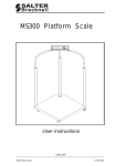
1
S122
Light Industrial Scale
User / Service Instructions
*76104-180*
ENGLISH
76104-180 Issue 0
21.07.2004
IMPORTANT
Before using the scale for the first time remove foam
packing from under the shroud.
1. Lift off weigh plate
2. Remove 4 x foam packaging blocks
3. Replace shroud
©Salter Brecknell 2005. All rights reserved.
The information contained herein is the property of Salter Brecknell Limited and is
supplied without liability for errors or omissions. No part may be reproduced or used
except as authorized by contract or other written permission. The copyright and the
foregoing restriction on reproduction and use extend to all media in which the
information may be embodied.
Contents
page no.
1
Warnings
1.1
1.2
1.3
1.4
1.5
Electrical installation
Risk of electric shock
Additional service precautions
Safe handling
ESD handling precautions
2
Introduction
2.1
2.2
2.3
Features
Keys
Error messages
3
Using the scale
3.1
3.2
3.3
3.4
3.5
3.6
3.7
3.8
3.9
3.10
3.11
Zeroing the scale
Data entry keys
Selecting weighing or counting
Using the backlight (option)
Switching between kgs and lbs
Sampling
Counting
Totalizing
Recalling totals
Canceling totals
Checkweighing
3.11.1 Setting check-weighing limits
3.11.2 To set the lower limit
3.11.3 To set the higher limit
3.11.4 To set the alarm
S122 User / Service Instructions
7
7
7
8
8
9
10
12
15
15
16
16
16
17
18
19
19
20
21
4
Contents
3.11.5 Limit indicators
3.12 Using tares
4
Installation/Maintenance
4.1
4.2
4.3
4.4
4.6
Connecting the column
Connecting the indicator
Opening the covers
RS232 PIN assignments
Replacing a load cell
5
Configuration Mode
5.1
25
28
30
31
32
33
Entering configuration mode
5.1.1 Service mode keys
5.2 Configuration menu
5.2.1 F6 - exiting configuration mode
5.3 F0 - weight calibration
5.4 F1 - specification settings
5.4.1 Keyboard check
5.5 F2 - noise filter setting
5.6 F3 - zero display setting
5.7 F4 - checkweighing function
5.8 F5 - print option
5.8.1 Printer outputs
5.8.2 RS232 interface specification
5.8.3 Data format
5.9 F6 - exiting configuration mode
5.10 F7 - displaying the internal count
5.11 F8 - setting the hold function
5.12 F9 - software lock
5
34
35
36
37
38
40
40
44
45
46
48
55
55
56
58
S122 User / Service Instructions
Contents
Wiring Diagrams
6.1
6.2
6.3
Power supply connections
Main board connections
Load cell connections
7
Parts Lists
7.1
7.2
Illustrated part lists
Additional parts
S122 User / Service Instructions
58
59
60
61
62
6
1.1 Electrical installation
1
Warnings
1.1
Electrical installation
1 Warnings
The power cord must be connected to a supply outlet with a
protective earth ground. The electrical supply at the socket
outlet must provide over current protection of an appropriate
rating.
Pluggable equipment must be installed near an easily
accessible socket outlet. Permanently connected equipment
must have a readily accessible disconnect device
incorporated in the fixed wiring.
For your protection all (110V or 230V) equipment used
out of doors or in wet or damp conditions should be supplied
from a correctly fused source and protected by an approved
RCD to BS7071 or BS7288 or BS4293. IF IN DOUBT SEEK
ADVICE FROM A QUALIFIED ELECTRICIAN.
1.2
Risk of electric shock
This equipment is powered by AC voltage which presents
an electric shock hazard.
Always completely disconnect the power supply:
1.3
7
●
Before removing the scale covers
●
Before performing any routine maintenance
●
Before cleaning the scale
Additional service precautions
●
When the covers are removed, do not apply power to the
unit unless specifically instructed to do in this handbook.
●
When working on live equipment, exercise great care,
use insulated tools and test equipment, and do not work
alone.
S122 User / Service Instructions
1 Warnings
1.4
1.4 Safe handling
●
When testing or fault finding, exercise extreme care.
Ensure that any test equipment used is in good condition
and capable of with standing the existing voltages.
●
All tools used must have insulated handgrips. Test probes
and jumper leads must be in good condition with
adequate insulation. Test probes with claw ends and
jumper leads must not have insecure parts that may fail
during use.
Safe handling
When lifting, moving or supporting the scale, take its
weight into consideration.
1.5
ESD handling precautions
When handling printed circuit boards and electronic
components, observe the following ESD handling
precautions:
8
●
Wear an grouned antistatic wrist strap.
●
Ensure that all electronic components/boards are stowed
appropriately, by use of conductive/antistatic work
surfaces and packaging.
S122 User / Service Instructions
1 Features
2 Introduction
2
Introduction
2.1
Features
1.
High performance A/D converter.
●
0.3µv/ sensitivity
●
Sample speed 16 times / second
●
Maximum resolution : 15000
●
Non-linearity 0.01 % FS
●
-1 mv ~ +5 mv
●
Used range -1 mv ~ +14 mv
●
Load cell excitation power 5VDC ±5% 100mA.
2.
Adjustable noise filter setting for the range of stability
from 01 ~ 15.
3.
Depending on the calibration division:
●
Standard division (under 10000)
Capacity and weight must be calibrated.
●
High precision division (over 10000 to 150000
divisions)
Linearity, capacity and weight must be calibrated.
4.
Option with RS232 output .
5.
Three options for the HOLD function.
6.
AC / DC power supply.
7.
LCD display.
8.
Auto-power cut off to ensure performance stability.
Power is cut off automatically if the power is below the
low battery warning.
9.
Built-in backlight.
S122 User / Service Instructions
9
2 Introduction
2.2
2.2 Keys
Keys
ZERO
Zero key. Remove any weight on the platform before
pressing the key.
Data entry key. Increments the value of the selected
digit.
Displays the backlight option.
ENTER
Data entry key. Go to the next digit.
CLEAR ENTRY
Resets all values on the current display to zero.
Selects units of measure.
Switches between kgs and lbs.
COUNT
SAMPLE
Selects counting mode.
Sample key. Displays the number of items in the
sample.
Totalize key. Displays the count number and total
weight each time you add a weight to the platform.
Remove the weight from the platform when finished.
RECALL
Recall totals. Displays the count number and then
the total for a few seconds. To cancel totals press
CLEAR ENTRY
while the count number or total is
displayed.
10
S122 User / Service Instructions
2.2 Keys
TARGET
TARE
2 Introduction
Sets checkweighing limits and beep option when in
counting mode.
Tares off the displayed weight of a container.
Enables you to enter a tare value when no weight is
RECALL
on the platform. To view a tare press
followed by the tare key. To cancel a tare remove the
container and press the tare key. To cancel a preset
CLEAR ENTRY
tare press
S122 User / Service Instructions
while the tare is displayed.
11
2.3 Error messages
2.3
2 Introduction
Error messages
E1
When the scale is switched on, the weight on the
platform is above or greater than the automatic zero
range (greater than 10% of the capacity of the scale).
Make sure that there is no weight on the platform. If the
error persists, re-calibrate the machine.
E2
When the scale is switched on, the weight on the
platform is below or lower than the automatic zero
range (greater than 10% of the capacity of the scale).
Correct service set up procedure has not been
followed. Ensure calibration weight is applied and
removed exactly in accordance with instructions.
E3
Not used.
E4
The weight on the platform is unsteady.
E5
There is a problem with the load cell. Check the wiring
(see page 60). If the error persists, replace the load cell
(see page 33).
E6
The internal zero value is greater than 360,000. The
error may occur in calibration mode.
E7
The internal zero value is less than 240,000. The error
may occur in calibration mode.
E8
This message will only appear for legal for trade scales.
If you are configuring the capacity of the scale, the
number of divisions cannot exceed 10,000.
--OL--
The weight is greater than the capacity of the scale.
------
Temporary error. Remove any weight from the platform,
switch off and then on again. If this error persists,
contact your authorized service agent.
S122 User / Service Instructions
12
Connecting to the AC power supply.
Make sure that there is no weight on the platform before switching
on.
Plug the power supply lead into the scale.
Make sure that the battery switch is set to the internal battery.
When the scale is connected to the AC power supply you will
see a red, yellow or green charging lamp depending on the
condition of the internal battery.
Using batteries
You can either use the internal rechargeable battery or use 6 size
’D’ cell batteries (alkaline batteries are recommended).
Use the battery switch to select either the internal battery or the ’D’
cells.
When this symbol flashes, you should either replace the ‘D’ cell
batteries or recharge the internal battery.
Do not leave discharged batteries in the scale, as they may leak
and cause serious damage. Do not store the machine with 'D' cell
batteries in the battery compartment.
Recharging the internal battery
While the machine is connected to the AC power supply and
internal battery is being recharged, the power supply light will turn
red, yellow, and then green.
To maintain the rechargeable battery in good condition, it should be
kept fully charged wherever possible. If the battery is to be stored,
the rechargeable battery should be fully charged before storage
and then recharged at 3 month intervals.
Disposing of the scale.
The scale contains a lead-acid battery. When disposing of the
machine, you should take it to an appropriate recycling facility.
3 Using the scale
3.1 Zeroing the scale
Using the scale
3
Depending on the option of the machine, some functions
may not be available.
If the ▼ icon above the STABLE legend flashes while you are
using the scale, it means that the weight on the platform is
unsteady.
3.1
Zeroing the scale
Remove any weight from the platform.
ZERO
3.2
.
0000
lb
Data entry keys
Whenever you need to enter values when setting totalizing,
check weighing or pre-set tares, use the following keys:
Increments the value of the selected digit.
ENTER
Go to the next digit.
CLEAR ENTRY
Restore all settings on the current display to zero.
S122 User / Service Instructions
15
3 Using the scale
3.3
3.3 Selecting weighing or counting
Selecting weighing or counting
COUNT
Weighing mode
Counting mode
If no sample size has been set you will be prompted to sample
some items.
3.4
Using the backlight (option)
Each press of the backlight key shows:
bL.
bL.
On
OFF
bL.AUtO
Always on
Always off
Automatic backlight
If set to automatic, the backlight comes on automatically when
the indicator is being used. A backlight may not be available
on some scale.
3.5
16
Switching between lbs and kgs
S122 User / Service Instructions
3 Using the scale
3.6 Sampling
3.6
Sampling
When selecting the number of items you wish to use as a
sample remember that the larger the sample size, the more
accurate the counting will be.
Display sample number
SAMPLE
C
C
C
C
Place sample items on the platform
10
20
50
100
COUNT
If you see ▼ above the piece weight icon it means that the
unit weight of each item is too small and this may lead to an
inaccurate count.
Unit weight too small
SAMPLE
PIECE
WEIGHT
C
C
C
C
10
20
50
100
COUNT
S122 User / Service Instructions
17
3 Using the scale
3.7 Counting
If you see ▼ above the add to sample icon it means that the
weight of the sample is too small. Unless you increase the
weight of the sample the count may be inaccurate count. You
should select a greater number of samples and add these to
the scale.
Weight of sample too small
SAMPLE
ADD TO
SAMPLE
C
C
C
C
10
20
50
100
COUNT
3.7
Counting
Select either weighing or counting mode:
COUNT
Weighing mode
Counting mode
If you select counting mode and no sample size has been set
you will be prompted to sample some items.
18
S122 User / Service Instructions
3 Using the scale
3.8 Totalizing
3.8
Totalizing
For each weight that you want to add:
lb
ADD
The count number and then the total weight will each be displayed
for a few seconds.
lb
Remove the weight from the platform when finished.
3.9
Recalling totals
The count number and then the total will each be displayed for
a few seconds before returning to the current display.
RECALL
- 0 004 -
S122 User / Service Instructions
lb
2 04 3 lb
19
3 Using the scale
3.10
3.10 Canceling totals
Canceling totals
Press the clear key while the count number or total is displayed.
RECALL
20
CLEAR ENTRY
S122 User / Service Instructions
3 Using the scale
3.11 Checkweighing
3.11
Checkweighing
3.11.1 Setting check-weighing limits
Select either weighing or counting mode:
COUNT
Weighing mode
Counting mode
If you select counting mode and no sample size has been set
you will be prompted to sample some items.
Display sample number
Place sample items on the platform
SAMPLE
C
C
C
C
10
20
50
100
COUNT
S122 User / Service Instructions
21
3 Using the scale
3.11 Checkweighing
3.11.2 To set the lower limit
Example: 50 items
TARGET
0- - - - L
To move along the display:
ENTER
4 times
00000l
To change the displayed value:
5 times
00005 l
To move along the display:
ENTER
00005 0
twice
To enter the lower limit:
ENTER
0- - - - H
22
S122 User / Service Instructions
3 Using the scale
.11 Checkweighing
3.11.3 To set the higher limit
Example: 1000 items
To move along the display:
ENTER
twice
000- -- HH
000-
To change the displayed value:
001000
4 times
To enter the higher limit:
ENTER
0- b
4
S122 User / Service Instructions
23
3 Using the scale
3.11 Checkweighing
3.11.4 To set the alarm
Example: beep when between targets
To move along the display:
ENTER
00b
To change the displayed value:
01b
To enter the alarm setting:
ENTER
0
The target beep can be:
00 = No target beeps
01 = Beep when between targets
02 = Beep when outside targets
3.11.5 Limit indicators
While using the scale you will see the following indicators to tell
you the status of the check-weighing:
LOW
The weight/number of items is below the lower limit.
OK
The weight/number of items is between the upper and lower
limit.
HIGH
24
The weight/number of items is above the upper limit.
S122 User / Service Instructions
Using tares
If you select counting mode and no sample size has been set you will be
prompted to sample some items.
Creating a tare
Viewing a tare
Canceling a tare
Creating a preset tare
Example: 1lb
Reviewing a pre-set tare value
Canceling a pre-set tare
4.1 Connecting the column
4 Installation/Maintenance
4
Installation/Maintenance
4.1
Connecting the column
1.
Lift the weigh plate off the platform and remove the
packing material.
2.
Thread the load cell cable A through the column.
3.
Fasten the column to the platform using the Allen key B
provided.
C
A
D
E
B
4.
Remove the knob C from the bracket D and slide the
hinge apart slightly so that the plug can be threaded
through the center of the bracket. Reassemble the
bracket.
S122 User / Service Instructions
28
4 Installation/Maintenance
29
4.1 Connecting the column
5.
For legal for trade scales, make sure that the grounding
connector E is attached to the lip of the column. If a
ferrite bead is used it should hang on wire between connector
A and bracket D.
6.
Fasten the bracket to the column. Make sure that the
clamp is at the back of the scale.
7.
For legal for trade scales in US territory the scale must
be sealed in the following manner.
S122 User / Service Instructions
4.2 Connecting the indicator
4.2
4 Installation/Maintenance
Connecting the indicator
1.
Slide the indicator onto the bracket until it clicks into
place.
2.
Plug the connector from the platform into the indicator.
A
B
3.
To adjust the angle of the indicator, loosen the knob A
and move the indicator until it clicks into the required
position.
4.
To remove the indicator, disconnect, then press the
release catch B and carefully slide the indicator off the
platform.
S122 User / Service Instructions
30
4 Installation/Maintenance
4.3
4.3 Opening the covers
Opening the covers
You will need to remove the covers in order to set up RS232 PIN
connections.
Electrostatic sensitive device
Observe all precautions for handling electrostatic
discharge sensitive devices.
31
1.
If required, remove the indicator from the column.
2.
Remove the battery cover.
3.
Unscrew and remove the two cross-head screws.
4.
Press in the bottom cover at point A to release the clips
on either side of the head. Then carefully slide the
covers apart. You do not need to disconnect any of the
wiring.
5.
To set up the PIN connections for RS232
communications, see section 4.4.
6.
Reassemble the covers replacing the screws.
7.
Replace the indicator onto the column.
S122 User / Service Instructions
4.4 RS232 PIN assignments
4.4
4 Installation/Maintenance
RS232 PIN assignments
The RS232 serial communications board allows the indicator
to send data to an external device such as a printer or
computer. The default baud rate is 2400. To change the
settings see section 5.8. The wiring circuit of the RS232
communication board is shown on page
.
59.
J1 and J3 SHORT; J2 and J4 OPEN (default)
PIN 2
PIN 3
PIN 7
RXD
TXD
GND
Other pins are not used.
J2 and J4 SHORT; J1 and J3 OPEN
PIN 2
PIN 3
PIN 7
TXD
RXD
GND
Other pins are not used.
S122 User / Service Instructions
32
4.6 Replacing a load cell
4.6
4 Installation/Maintenance
Replacing a load cell
1.
Switch off and disconnect the scale from the AC
power supply.
2.
Remove the shroud.
3.
Disconnect and remove the indicator from the column.
4.
Remove the knob from the bracket and slide the hinge
apart slightly so that the plug can be threaded through
the center of the bracket. Reassemble the bracket.
5.
Remove the bracket from the top of the column.
6.
For legal for trade scales, remove the grounded connection.
7.
Remove the column.
8.
Remove the two clips holding the cable to the platform.
9.
Remove the four M8x 20mm socket head screws and
remove the load bridge.
Note: these bolts will be very tight.
10. Turn the platform over and remove the four M8x 20mm
socket head screws holding the load cell to the platform.
Note: these bolts will be very tight.
11. Remove the load cell. Desolder the plug and retain.
To replace the load cell, reverse the above procedure and
resolder the plug if necessary.
Torque settings for all bolts to the load cell are: 440 pound-force.
S122 User / Service Instructions
33
5.1 Entering configuration mode
5 Configuration Mode
5
Configuration Mode
5.1
Entering configuration mode
In order to enter configuration mode you must first set the
configuration switch to the unlocked position. The switch is
located under the tamper proof seal above the serial communication
socket on the right-hand side of the head.
Locked position
Unlocked position
Set the configuration switch to
the unlocked position.
S122 User / Service Instructions
34
5 Configuration Mode
5.1 Entering configuration mode
While the test is displayed,
press and hold the key until you
see ...
ZERO
Release the key.
5.1.1
Service mode keys
The following keys are available in service mode:
TARE
Accept the entered values and go to the next section.
CLEAR ENTRY
Cancel all values for the current display.
ENTER
Go to the next digit or field.
Increment the value of the current (usually flashing) digit.
ZERO
Go to previous digit
35
S122 User / Service Instructions
5.2 Configuration menu
5.2
5 Configuration Mode
Configuration menu
The menu consists of functions F0 to F9. To go down the
functions press
(F0 to F9). To go back up the functions
TARE
press
(F9 to F0).
Function number Function description
TARE
F0
F1
F2
F3
F4
F5
F6
F7
F8
F9
See page...
Weight calibration
Page 38
Specification settings
Page 40
Noise filter setting
Page 44
Zero display setting
Page 45
Check-weighing settings
Page 46
Print option
Page 48
Exit configuration mode
Page 37
Display internal value
Page 55
HOLD function
Page 56
Software lock
Page 58
S122 User / Service Instructions
36
5 Configuration Mode
5.2.1
5.2 Configuration menu
F6 - exiting configuration mode
Remember to set the configuration switch back to the locked
position.
TARE
F6
or
ENTER
.
0000
lb
Set the configuration switch to
the locked position.
37
S122 User / Service Instructions
5.3 F0 - weight calibration
5.3
5 Configuration Mode
F0 - weight calibration
●
Ensure the hold function (F8) is set to hold 0.
Please remember .....
The calibration weight must be over 0 weight or any weight
less than the full capacity of the machine.
ENTER
2Ero
ENTER
0--.--C
kg
Unit of calibration
To change the unit of
calibration:
0 --.--C
lb
New unit of calibration
To change the flashing digit:
1--.--C
kg
lb
To go to the next digit:
ENTER
10-.--C
S122 User / Service Instructions
kg
lb
38
5 Configuration Mode
5.3 F0 - weight calibration
Repeat to enter the calibration
weight.
For example, to enter 30 lb:
ENTER
twice
3 times
ENTER
3 times
030.000
kg
lb
ENTER
030.000
kg
030.000
kg
lb
Place the calibration weight on
the platform. Press the enter
key.
ENTER
lb
Remove the calibration
weight.
.
0000
39
lb
S122 User / Service Instructions
5.4 F1 - specification settings
5.4
5 Configuration Mode
F1 - specification settings
Ensure the hold function (F8) is set to hold 0.
●
5.4.1
Keyboard check
You can perform a keyboard check. If the correct code
appears when you press a key then you know that the key is
functioning correctly, see the table below. You cannot check
ENTER
the
key as it takes you to the next step.
Function key
Code
Function key
Code
RECALL
COUNT
3E
PRESET TARE
27
CLEAR ENTRY
3d
2b
37
1E
ZERO
TARGET
TARE
3b
1d
2E
17
SAMPLE
ADD
2d
S122 User / Service Instructions
40
5 Configuration Mode
5.4 F1 - specification settings
FI
ENTER
set
To check a key press the key:
17 SEt
ENTER
273027
Internal count
If there is an error
you will see ...
E63027
E 73 027
Internal count
less than 240,000
Internal count
more than 360,000
41
S122 User / Service Instructions
5.4 F1 - specification settings
5 Configuration Mode
ENTER
U00000
Examples:
Unit options are:
digit 1
digit 2
digit 3
digit 4
digit 5
digit 6
kg only
lb only
kg, lb units
lb, kg units
1= kg, 2= lb
0= no 2nd unit
1= kg, 2= lb
Must be set to 0
0= kg display
1= g display
0= lb display
1= lb, oz display
Not used
100xxx
200xxx
120xxx
210xxx
To change the flashing digit:
200000
lb primary unit
To go to the next digit:
ENTER
200000
secondary unit
Repeat until you have entered
the required oiptions.
kg displayed
not used
kg secondary unit
Example: 210010
21 = dual units lb and kg
digit 4 = kg displayed
digit 5 = lb, oz displayed
210010
Must be 0
lb primary unit
lb, oz displayed
S122 User / Service Instructions
42
5 Configuration Mode
5.4 F1 - specification settings
ZERO
C00000
kg
lb
ENTER
Press
and
to
130lb capacity
enter the required capacity:
Full capacity + 9d
max lb wight=(max kg
wghtx2.24)
60kgx20g 006018
150kgx50g 015045
300kgx100g 003009
130lbx0.05lb 013045
330lbx0.10lb 003309
660lbx0.20lb 066010
ZERO
ENTER
Press
and
to
enter the weight settings:
digit 1 = divisions (1, 2, or 5)
digit 2 = decimal places
(1, 2, or 3)
digits 3 - 6 = 0
013045
kg
d00000
kg
530000
kg
lb
lb
lb
Divisions=0.05lb
ZERO
43
S122 User / Service Instructions
5.5 F2 - noise filter setting
5.5
5 Configuration Mode
F2 - noise filter setting
The range of stability is from 01 to 15. Enter a setting
appropriate to the environment.
●
The higher the value the quicker the machine reaches
stability but weighing is less accurate.
●
If the environment is unstable enter the value 15.
●
If the environment is stable enter the value 05. This is the
default value.
●
Ensure the hold function (F8) is set to hold 0.
F2
twice
ENTER
fiL 05
To change the value:
fiL 06
ENTER
S122 User / Service Instructions
F2
5 Configuration Mode
5.6
5.6 F3 - zero display setting
F3 - zero display setting
MUST BE SET TO 0 AT LEGAL FOR TRADE SCALES.
●
If the load cell gives unstable readings set to 5 which is
the maximum.
●
If the load cell gives stable readings set to 0 which is the
minimum.
●
Ensure the hold function (F8) is set to hold 0.
F3
3 times
ENTER
2Er o 0
3 = zero display reading within
Zero display setting
3 divisions
0 = default zero display reading within4 = zero display reading within
1 division
4 divisions
2 = zero display reading within
5 = zero display reading within
2 divisions
5 divisions
To change the value:
2Er o 1
ENTER
45
F3
S122 User / Service Instructions
5.7 F4 - checkweighing function
5.7
5 Configuration Mode
F4 - checkweighing function
●
Ensure the hold function (F8) is set to hold 0.
F4
4 times
ENTER
0--.--L
To cancel the high/low limits and
alarm setting:
ENTER
kg
lb
000.000 kg
lb
5 times
F4
ENTER
ENTER
Press
low limit = 2lb
and
to enter the required low limit:
002.000 kg
lb
Low limit > 10 divisions
ENTER
0--.--H
S122 User / Service Instructions
kg
lb
5 Configuration Mode
5.7 F4 - checkweighing function
ENTER
Press
high limit = 2.5lb
and
to
002.500 kg
enter the required high limit:
lb
High limit ≥ low limit
ENTER
0-b
Check-weighing alarm digit 1
0 = Stable, beeps and LCD on
1 = Stable, beeps whether
stable or not and LCD on
2 = Whether stable or not,
beeps and LCD on
kg
lb
Check-weighing alarm digit 2
0 = No beeps
1 = OK (over low limits and under
high limits), beeps
2 = Under or equal to low limit
(must be over 10d) and
over or equal to high limit, beeps
LCD indication
LOW
OK
HIGH
ENTER
Press
01 = Beep between targets
and
to
01b
enter the required alarm setting:
ENTER
47
kg
lb
F4
S122 User / Service Instructions
5.8 F5 - print option
5.8
5 Configuration Mode
F5 - print option
●
Ensure the hold function (F8) is set to hold 0.
●
To transmit to a computer short pins J1 and J3.
●
To transmit to a serial printer short pins J2 and J4.
F5
5 times
ENTER
Printer options are shown below:
0 Printing disabled.
1 Stable transmit for a PC.
2 Continuous printing for a PC.
ENTER
3 Simple printing for serial printer. Press
to print.
ENTER
4 Full printing for serial printer. Press
to print.
5 Stable printing (accumulation).
ENTER
6 Full printing for EZ-2 printer. Press
ENTER
7 EZ-2 printer. Press
S122 User / Service Instructions
to print.
to print.
5 Configuration Mode
5.8 F5 - print option
To change the printer setting:
Example EZ-2 printer
7 times
ENTER
Default baud rate
Display the setting required by
the EZ-2 printer:
Baud rate options are:
1200, 2400, 4800, 9600
3 times
New baud rate
ENTER
49
F5
S122 User / Service Instructions
5.8 F5 - print option
5.8.1
5 Configuration Mode
Printer outputs
The S122 can be connected to a computer running a suitable
application or a 40 column printer, see the typical outputs below.
rnP 1
ST,NT,+
ST,NT,+
ST,NT,+
ST,NT,+
ST,NT,+
ST,TR,+
ST,NT,+
ST,NT,+
ST,NT,+
ST,NT,+
PC stable transmit
When the weight is stable
press the key to transmit
each transaction to the PC.
1.000lb
1.000lb
2.002lb
2.004lb
0.000lb
1.000lb
0.990lb
0.990lb
1.000lb
1.000lb
ENTER
ST=Stable weight
NT=Gross weight
TR=Net weight in operation
ENTER ENTER
TARE
rnP 2
UlbS,NT,+1.000lb
US,NT,+ 1.000lb
ST,NT,+ 1.000lb
ST,NT,+ 1.000lb
US,NT,+ 1.000lb
US,NT,+ 1.000lb
ST,NT,+ 0.890lb
ST,NT,+ 0.890lb
ST,NT,+ 1.000lb
ST,NT,+ 1.000lb
Continuous
transmission to PC
The weight is continuously transmitted to the PC.
S122 User / Service Instructions
5 Configuration Mode
5.8 F5 - print option
rnP 3
Simple mode for serial printer
To transmit each transaction to the
printer:
ADD
ENTER
or
To transmit the total to
the printer:
S/N
WT/lb
________
001
2.000
002
1.000
________
0002
3.000
ENTER ENTER
rnP 4
Full mode for serial printer
To transmit each transaction
to the printer:
TICKET
G
T
N
NO.0001
1.000lb
0.000lb
1.000lb
TICKET
G
T
N
NO.0002
2.000lb
0.000lb
2.000lb
TICKET
G
T
N
NO.0003
2.000lb
1.000lb
2.000lb
ADD
ENTER
or
To transmit the total to
the printer:
ENTER ENTER
TOTAL NUMBER
OF TICKETS 0003
TOTAL
NET
4.000lb
51
S122 User / Service Instructions
5.8 F5 - print option
rnP
5 Configuration Mode
5
Stable printing (accumulation)
To transmit each transaction
to the printer:
ADD
ENTER
or
To transmit the total to
the printer:
S/N
WT/lb
________
001
1.000
002
2.000
003
2.000
004
2.000
005
2.000
________
005
9.000
ENTER ENTER
rnP
6
Full mode for EZ-2 printer
To transmit each transaction to the
printer:
ADD
ENTER
or
To transmit the total to
the printer:
ENTER ENTER
S122 User / Service Instructions
TICKET
G
T
10152
03
TICKET
G
T
10152
03
TICKET
G
T
N11
03
NO.0001
1.000lb
0.000lb
1.000lb
NO.0002
1.000lb
0.000lb
1.000lb
NO.0003
2.000lb
0.000lb
2.000lb
5 Configuration Mode
rnP
5.8 F5 - print option
7
Stable transmit to EZ-2 printer
To transmit each transaction to
the printer:
5.8.2
151123+
151123+
151123+
151123+
151123+
151123+
1.000lb
1.000lb
0.000lb
0.000lb
2.000lb
2.000lb
RS232 interface specification
I. Mode : EIA-RS0232 C’s UART signal
II. Format:
Baud rate
Can select
1200, 2400, 4800, 9600 BPS
Start bit
53
Data bit
8 bits
Parity bit
None
Stop bit
1 bit
Code
ASCII
Data bits
Stop bit
S122 User / Service Instructions
5.8 F5 - print option
5.8.3
5 Configuration Mode
Data format
Data format for stable and continuous transmission.
Head 1
(2 bytes)
Head 2
(2 bytes)
OL Overload, under load
ST Display is stable
NT Net mode
US Display is unstable
GS Gross mode
Data (8 bytes)
2D (HEX)= "-" (minus)
2E (HEX)= "."
(decimal point)
Unit (2 bytes)
kg
=6B (HEX) ; 67 (HEX)
lb
=6C (HEX) ; 62 (HEX)
Example 1: +0.876kg stable weight and net value
Example 2: -1.568lb unstable weight and net value
S122 User / Service Instructions
5 Configuration Mode
5.9
5.9 F6 - exiting configuration mode
F6 - exiting configuration mode
See page 37.
5.10
F7 - displaying the internal count
●
Ensure the hold function (F8) is set to hold 0.
F7
7 times
ENTER
273027
Internal count
ENTER
55
F7
S122 User / Service Instructions
5.11 F8 - setting the hold function
5.11
5 Configuration Mode
F8 - setting the hold function
ENTER
You can set up the hold function so pressing the
key
prints the displayed value. You must also set up the correct
transmit baud rate for the receiving device.
Hold 0
No hold function.
Hold 1
When the weight is continuously changing the scale
automatically holds the maximum value.
002.500
lb
ENTER
Press any key other than
to clear the hold.
Hold 2
When the weight becomes stable the scale automatically
ENTER
holds the displayed value. Press any key other than
clear the hold.
to
Hold 3
When the weight becomes stable the scale automatically
holds the displayed value. The hold clears when the weight is
removed and the machine returns to zero weight.
S122 User / Service Instructions
5 Configuration Mode
5.11 F8 - setting the hold function
F8
8 times
ENTER
h o1d-0
kg
h o1d-3
kg
lb
To change the hold setting:
ENTER
57
lb
F8
S122 User / Service Instructions
6.1 Power supply connections
6 Wiring Diagrams
6 Wiring Diagrams
Electrostatic sensitive device
Observe all precautions for handling electrostatic
discharge sensitive devices.
6.1
Power supply connections
Battery
selector
switch
Black
'D' cell batteries
Red
AC Power
in socket
Internal
rechargeable
battery
On/off
Switch
Note: All connections are soldered.
S122 User / Service Instructions
Red
Brown
Yellow
Orange
Blue
Green
To mainboard
= 0.1µFCapacitor
6.2 Wiring Diagrams
6.2
6.2 Main board connections
Main board connections
S122 User / Service Instructions
6.3 Load cell connections
6.3
Load cell connections
S122 User / Service Instructions
6.3 Wiring Diagrams
7.1 Illustrated part lists
7
Parts Lists
7.1
Illustrated part lists
7.1 Parts Lists
User/service Instructions
76103-986
S122 User / Service Instructions
7.2 Parts Lists
7.2
7.2 Additional parts
Additional parts
Description
Part number
Sealing screw kit
SER/L120/0002
Ground spring
SER/L120/0003
On/Off switch
1111001111
Battery selector switch
1111001221
Load cell connector - male 5-way
1240001051
Load cell connector - male 6-way
1240001061
Load cell connector - female - 5-way
1240001050
Load cell connector - female - 6-way (approved)
1240001060
Keyboard
KB4T1A0A2000
Keyboard overlay
1220355122
S122 User / Service Instructions
The address of your Salter Brecknell center is
This document contains a general guide only of the product and shall not form part of any contract unless specifically agreed by Salter Brecknell Weighing in writing
in each case on the Order Acknowledgement. The specification of the products described herein may vary from time to time and may be altered without notice.
USA
Salter Brecknell Weighing Products USA
1000 Armstrong Drive
Fairmont
MN 56031
Toll Free: 800-637-0529
Phone: 507-238-8702
Fax:
507-238-8271
Email: [email protected]
Web site: www.salterbrecknell.com
UK and Europe
Salter Brecknell Weighing
P.O. Box 9533
Smethwick
West Midlands
B66 2TE
Tel: +44 (0) 870 444 6132
Fax: +44 (0) 870 010 2241
Email: [email protected]
Web site: www.averyweigh-tronix.com