1
www.pulsar.pl
PowerSecurity
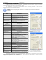
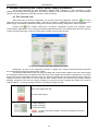
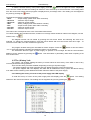
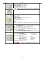
Information window with the PSU type
Current battery status:
- battery voltage [V]
- charging level
- TEST; performing battery test (see section 4.4)
- battery fuse status
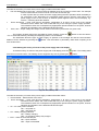
In case of the fuse activation, the symbol changes to red and
flashes.
Input of collective failure EXT IN status.
In case of the input activation, its backlight changes into red.
Status of the technical outputs of the PSU.
EPS - AC power ON indication
open, red backlight
closed, green backlight
PSU – PSU failure indication
open, red backlight
closed, green backlight
APS – battery failure indication
open, red backlight
closed, green backlight
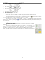
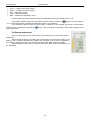
= AC power failure
= AC power ON:OK.
= failure
= PSU status OK.
= battery failure
= battery OK.
Failure example, the output is open and highlighted in red.
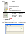
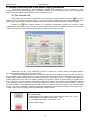
4.2 The „Diagrams” tab
The ”Diagrams” tab enables reading the history of the parameters (current, voltage) stored in the internal
memory of the PSU and reading the values from the charts. The ”Diagrams” tab is available only for power supplies
with LCD display.
During normal operation, the PSU records the voltage and current values at the AUX output circuit and
saves them in the internal nonvolatile memory. Recording is performed at 5 minute intervals and the memory
capacity allows for about 6100 entries. The data is stored in the circular buffer: when the memory is full, the oldest
entries are overwritten by the new ones.
Fig. 13. The „Diagrams” tab.
11