1
Manual de Instrucciones de Operación y Piezas
ESP25
Installation
Method 2
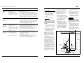
Problema
Posible(s) Causa(s)
Acción Correctiva
(Continued)
La bomba no
funciona
1. Conexiones flojas
2. Batería baja o defectuosa
3. El interruptor de flotador no puede
subir y bajar como es necesario
4. Fusible defectuoso o quemado
1. Revise todas las conexiones
2. Revise la batería y reemplácela si está baja o defectuosa
3. Compruebe que el cordón flexible del interruptor de flotador
tiene longitud suficiente para permitir que la bomba funcione
4. Revise el fusible interno ubicado dentro de la caja de control.
Desconecte el cargador del tomacorrientes de la pared y retire
el fusible. Si está quemado, cámbielo por un fusible tipo automotor de 20 amperios
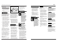
3. Cut a 4’ section of 1-1/4” or 1-1/2”
diameter rigid PVC pipe. Cement
1-1/4” pipe to a threaded fitting.
Cement 1-1/2” pipe into pipe
coupling. Attach 1-1/4” pipe
section to the ESP25 discharge
adapter.
If a separate, dedicated discharge is
not possible as in Method 1, the ESP25
pump can be tied in to the ACoperated pump’s discharge pipe by
installing a “Y” connector. Two check
valves will be required.
Guía de diagnóstico de averías
El motor zumba,
pero la bomba no
funciona
1. Batería defectuosa
2. El impulsor está bloqueado
La bomba
funciona pero
bombea poca o
nada de agua
1. Revise la válvula que falta o que
está mal instalada
Los ciclos de la
bomba son muy
frecuentes
2. Obstrucción en el tubo de descarga
3. La longitud y/o altura del tubo de
descarga excede la capacidad de la
bomba
4. Batería baja o defectuosa
1. La longitud del cconector del
flotante en el interruptor de
flotador es muy corta
2. Revise los problemas de válvulas
1. Revise la batería y reemplácela si está baja o defectuosa
2. Desconecte la bomba, retire la rejilla y revise para ver si el
impulsor puede girar libremente. Si el impulsor está bloqueado,
retire los 8 tornillos en la parte inferior de la bomba para
liberar la caja que cubre el impulsor. Retire la obstrucción.
Vuelva a armar la bomba y vuelva a conectar.
1. Revise para asegurarse de que las válvulas de retención
instaladas entre la bomba primaria y la bomba de respaldo para
sumideros estén funcionando adecuadamente.
2. Revise si hay obstrucción y remuévala si es necesario
3. Si la línea de descarga está muy alta, tal vez necesitará instalar
una línea de descarga adicional a una altura inferiro
4. Revise la batería y cámbiela si está baja o defectuosa
1. La longitud del conector del flotante debe ser de 5,1 cm por lo
menos. Ajústelo si es necesario
PRECAUCION: Cerciórese de que el conector del flotante se
puede mover sin obstrucciones
2. Revise para asegurarse de que las válvulas de retención
instaladas entre la bomba primaria y la bomba de respaldo para
sumideros estén funcionando adecuadamente.
4. Screw on to pump discharge.
NOTICE
Be careful not to strip or cross thread
plastic fittings or check valves. Flex
hose is not recommended. Rigid PVC or
metal pipe is required for a permanent
installation.
5. Place the pump with the 4’ section
of PVC pipe on a solid, level surface
in the sump pit on an elevated
surface.
6. Attach a rubber check valve (sold
separately) to the top of the
discharge pipe. This will allow the
pump or check valve to be
removed easily for servicing.
1. Locate the ESP25 on a solid, level
surface in the sump pit. Do not
place the pump on a loose or sandy
surface. Small stones or sand may
damage the pump resulting in
potential pump failure.
2. The pump has a 1-1/4” NPT
discharge adapter. If a 1-1/2”
discharge pipe is desired, glue pipe
coupling to outside of adapter.
Smaller diameter piping will reduce
pump flow, rate and performance.
3. A check valve will be required in
the discharge line of BOTH the
Main AC pump and the ESP25
pump to prevent recirculation of
NOTE: Check valves can be placed
directly in the pump discharge if
desired. However, for ease of
disassembly, it is recommended that
check valves be placed above the sump
as shown in Figure 1.
The remainder of the discharge pipe
installation will vary depending on
individual circumstances. Using sound
plumbing practices, route the
discharge pipe to an exterior wall by
the shortest path. Keep turns to a
minimum because they reduce flow
output of the pump. The pipe that
exits the building structure should be
sloped downward so that water will
not freeze in the pipe.
When installing the separate discharge
pipe, drill through the outside wall
with appropriate drilling equipment.
Seal the hole to prevent water from
entering.
water into the sump pit. System will
not function without two check
valves.
4. Cut a 4’ section of 1-1/4” or 1-1/2”
diameter rigid PVC pipe. Cement
1-1/4” pipe to a threaded fitting.
Cement 1-1/2” pipe into pipe
coupling. Attach 1-1/4” pipe section
to the ESP25 discharge adapter.
5. Screw on to pump discharge.
NOTICE
Be careful not to strip or cross thread
plastic fittings or check valves. Flex
hose is not recommended. Rigid PVC or
metal pipe is required for a permanent
installation.
6. Place the pump with the 4’ section
of PVC pipe on the sump floor or
on an elevated surface if required.
7. Attach a rubber check valve (sold
separately) to the top of the
discharge pipe. This will allow the
pump or check valve to be removed
easily for servicing.
Floor
Joist
“Y”
Connector
45°
Elbow
Rigid PVC
Pipe
Charger
Check Valve
(See Step 10)
Check
Valve
(See
Step 10)
Battery Box
Float Tied to Discharge Line
ESP25 Pump
Existing Pump
Figure 2 - Method 2
6 Sp
3
www.waynepumps.com