1
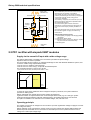
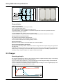
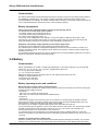
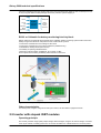
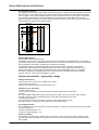
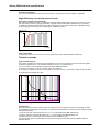
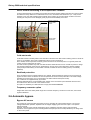
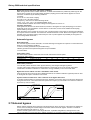
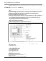
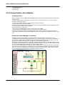
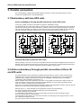
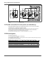
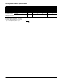
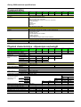
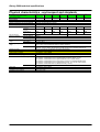
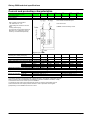
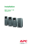
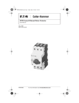
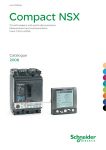
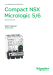
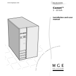
www.mgeups.com Galaxy 5000 20 to 120 kVA Technical specifications T H E U N I N T E R R U P T I B L E P O W E R P R O V I D E R Galaxy 5000 technical specifications Contents 1. Presentation ............................................................................................................... 2 1.1 Galaxy 5000 range.......................................................................................................... 2 1.2 The answer to the most demanding situations............................................................. 3 2. Technical specifications ........................................................................................ 6 2.1 2.2 2.3 2.4 2.5 2.6 2.7 2.8 2.9 Operating principle ........................................................................................................ 6 PFC rectifier with sixpack IGBT modules ..................................................................... 7 Charger........................................................................................................................... 8 Battery ............................................................................................................................ 9 Inverter with sixpack IGBT modules ............................................................................. 12 Automatic bypass .......................................................................................................... 16 External bypass ............................................................................................................. 16 UMI (User-machine interface) ........................................................................................ 16 Communication and software........................................................................................ 17 3. Parallel connection .................................................................................................. 19 3.1 3.2 3.3 3.4 Redundancy with two UPS units ................................................................................... 19 Active redundancy through parallel connection of three or four UPS units ............... 19 Parallel connection for more power (no redundancy).................................................. 20 External bypass ............................................................................................................. 20 4. Functions .................................................................................................................... 21 4.1 Main standard functions ................................................................................................ 21 4.2 Available options ........................................................................................................... 21 5. Installation .................................................................................................................. 21 5.1 Modular UPS cabinets ................................................................................................... 21 5.2 Cabinet layout ................................................................................................................ 22 Tables of characteristics.............................................................................................. 23 Electrical characteristics ..................................................................................................... 23 Communication .................................................................................................................... 24 Physical characteristics....................................................................................................... 24 Environment and standards ................................................................................................ 25 Current and protection characteristics ............................................................................... 26 MGE UPS SYSTEMS SPTC5 500 UK – 09/2005 page 2 Galaxy 5000 technical specifications 1. Presentation 1.1 Galaxy 5000 range Optimised power protection offering high availability and upgradeability for data centres, telecommunications and industrial processes Galaxy 5000 7 power ratings: 20 - 30 - 40 - 60 - 80 - 100 - 120 kVA Three-phase input and output Parallel connection of up to six UPS units, i.e. 6 x 120 = 720 kVA On-line double conversion (VFI) providing voltage regeneration and isolation from the distribution system Automatic and manual bypasses PFC rectifier with sixpack IGBT modules to avoid upstream distortion (upstream THDI < 3%) and with a PF close to 1 Sixpack IGBT modules designed to reduce the number of connections for greater reliability, compactness and easy access from the front Sealed lead-acid batteries installed in the UPS cabinet up to 80 kVA Backup times from 5 minutes to 4 hours and more with a rapid charger for more secure operation (recharge < 11 hours) Wide input-voltage range from 250 to 470 V to handle disturbed distribution systems High overload and discrimination capacity Input-current limiting during genset start Multilingual, graphic display, high resolution quarter VGA Battery digital monitoring by Digibat (calculation of real backup time and remaining battery life) and block by block monitoring Monitoring and communication possibilities via networks and the web with preventive maintenance (Life Cycle monitoring) Low TCO due to an optimised environment (cables, protection, genset compatibility), small footprint, high efficiency and monitoring of multiple UPS units using Enterprise Power Manager software The culmination of long experience The new range of Galaxy 5000 three-phase UPSs, from 20 to 120 kVA, are the result of over 40 years of experience at MGE UPS SYSTEMS, the leading firm in complete, high-quality solutions for electrical energy. It combines both innovation and the reliability characteristic of the Galaxy ranges. Galaxy 5000 uses sixpack IGBT modules and has fewer components and connections. The result is high performance in a compact package offering easy access through the front to all components for simple maintenance. Compactness is enhanced by placing the sealed lead-acid batteries in the UPS cabinets up to 80 kVA. The modular design means customised solutions become standard procedure and can be adapted to changes in the installation through parallel connection of up to four UPS units with redundancy if necessary, for very high availability. Galaxy 5000 is part of an overall approach (expert advice, design studies and audits, complete hardware solutions, state-of-the-art services) that is the trademark of MGE UPS SYSTEMS. It can adapt to a wide array of installation architectures to precisely meet your needs. It can also be combined with other protection products from MGE UPS SYSTEMS such as the STS, synchronisation modules, intelligent PDUs, etc. The many advanced monitoring and communication possibilities for the UPS and the battery over standard MGE UPS SYSTEMS SPTC5 500 UK – 09/2005 page 3 Galaxy 5000 technical specifications networks and the web make for proactive maintenance that enhances the availability of the installation. MGE UPS SYSTEMS SPTC5 500 UK – 09/2005 page 4 Galaxy 5000 technical specifications Optimised protection for applications such as data centres, telecommunications and industrial processes Galaxy 5000 meets the needs of the most sensitive applications in terms of high energy availability, installation flexibility and control over operating costs through a set of specific advantages: Data centres - high energy quality and availability are combined with a wide range of power-upgrade possibilities from a few dozen to several hundred kVA, easily, in complete safety and without interrupting operations. Telecommunications - uninterrupted, mission-critical operation 24/365 is ensured by redundant architectures. Long backup times are guaranteed by continuous battery monitoring and installation supervision via computer networks or the internet. These systems increase availability and make it possible to plan preventive maintenance. Industrial processes - operation in severe environments is possible due to the robust electrical characteristics capable of handling disturbed distribution systems and a vast catalogue of options and functions (reinforced IP, Ni-Cad batteries, marine versions, etc.). Fig. 1 a-b-c. Applications. 1.2 The answer to the most demanding situations Highest availability The performance level of Galaxy 5000 contributes to providing high-quality energy 24/365 in all environments and for all applications. Double conversion (VFI as per IEC 62040-3/EN 62040-3), providing regeneration of the output voltage and frequency. PFC rectifier with sixpack IGBT modules to avoid disturbances on the upstream system: - low current distortion upstream, THDI < 3% - input power factor (PF) > 0.99. Digital control (free frequency) of the voltage combined with the sixpack IGBT modules, ensuring: - a wide input-voltage range from 250 to 470 V, depending on the percent load, suited to all types of applications and disturbed distribution systems - high quality and stability of the output voltage, THDU < 2% (linear and capacitive loads) - high dynamic performance for load-step changes (< 2% for 100 to 0% and for 0 to 100%), return to the +1% range (rms value) in less than 100 ms. Backup time remains available due to digital management of batteries and the Digibat system that checks and enhances battery status, and informs the user. The B1000 and Cellwatch battery-monitoring systems are available for monitoring of each battery block. Powerful standard charger for long battery backup times (several hours) and fast recharging (10 minutes of backup time in less than 11 hours and 4 hours of backup time in less than 24 hours, i.e. 90% of battery capacity). Discrimination due to high overload capacity (2.2 In for 1 second) and a permissible crest factor of 3 to 1. Redundancy with up to four UPS units to protect servers requiring high availability. Automatic static switch for no-break transfer to AC power if an internal fault occurs (fault tolerance). UPS servicing and replacement of communication cards and battery modules without interrupting operation. Cold start on battery power if AC power is not available. MGE UPS SYSTEMS SPTC5 500 UK – 09/2005 page 5 Galaxy 5000 technical specifications Flexibility Galaxy 5000 can meet the upgrade needs of sites, in terms of both power increases and different types of applications, without interrupting operation. Changes in available power - the initial power rating can be multiplied by four through parallel connection, in step with the needs of the application. Tailored batteries (sealed or vented lead acid, Ni-Cad) and backup times from 5 minutes to 4 hours, fast recharging. Many possible architectures through parallel connection of up to four modular units, isolated redundancy, redundant distribution with an STS (static transfer system). Catalogue of built-in options to cover all safety needs including lightning arrestors, backfeed protection to avoid injecting DC power upstream, industrial adaptation kits, etc. No derating of the active power, whether for inductive or capacitive loads. Operation without a neutral. Easy start-up and operation The most compact UPS in its category, Galaxy 5000 is easy to set up and install. It has intuitive user-machine interfaces based on graphics and pictograms to enhance safety and comfort: Black and white graphical display, wide (quarter VGA, 120 x 93 mm) and high resolution (320 x 240 pixels), easy to read under all lighting conditions. Step-by-step help on the screen for operations. Animated mimic diagram. Time-stamping of 2 500 events. Galaxy 5000 offers the entire MGE UPS SYSTEMS range of communication systems to: inform on UPS operation and the environment protect server data by automatic, clean shutdown of operating systems actively supervise an entire set of UPSs. These functions implement different protocols depending on the environment, including dry contacts, the JBus/Modbus protocols for communication with a BMS (Building Management System) and Ethernet for web supervision. Reduction in operating costs and the TCO The high level of availability protects against operating losses. But the cost must be proportionate to the risks covered and optimised. To that end, it is necessary to calculate the direct investment and installation costs as well as the operating costs (personnel, energy, maintenance, etc.). TCO analysis shows that Galaxy 5000 provides the best return on the investment. Reduced installation costs - System components (protection circuit breakers, cables, genset) can be sized to the precise need due to the absence of upstream harmonic currents (THDI < 3%). - System compactness, installation of batteries in the UPS cabinets up to 80 kVA and positioning with the back to the wall all reduce the Galaxy 5000 footprint. Reduced operating costs Galaxy 5000 efficiency is 94%, even at low percent loads. That means significant savings on the energy bill and in sizing air-conditioning and ventilation systems. Proactive maintenance Easy product maintenance was a major guideline in designing Galaxy 5000, with: - computer tools for improved servicing and diagnostics - remarkable access to all modules for fast and safe repairs - the Life-cycle monitoring system comprising a range of sensors for preventive maintenance on components such as batteries and capacitors. The system signals the approaching end of component life to the diagnostics tool for timely replacement and enhanced continuity of service for the protected application. MGE PowerServices High availability from MGE UPS SYSTEMS includes MGE PowerServices with: 900 experts and technicians in the field to ensure continuity of service 24/365 170 service centres in over 100 countries, stocked with original replacement parts, all checked and available within 4 hours 22 Teleservice centres. Services include support by experts using advanced tools for: Preliminary studies and site audits Commissioning and technical support suited to each context Maintenance contracts to manage and monitor the entire UPS system and maintain equipment in optimum operating condition Certified training for all intervention levels. MGE UPS SYSTEMS SPTC5 500 UK – 09/2005 page 6 Galaxy 5000 technical specifications 2. Technical specifications 2.1 Operating principle Purpose These technical specifications present the Galaxy 5000 three-phase uninterruptible power system (UPS), implementing sixpack IGBT modules and installed in series between the distribution system and a set of critical loads. This type of system is designed to supply the application with high-quality energy (precise tolerances) that is available without interruption (no outages or micro-outages) whatever the conditions on the distribution system. The Galaxy 5000 UPS configuration may comprise a single or parallel UPS units, with or without redundancy. Operating modes Galaxy 5000 UPSs are the double-conversion type (VFI as per IEC 62040-3/EN 62040-3), that regenerate the output voltage and frequency. This ensures consistently high-quality voltage to the critical loads and an isolation from the distribution system disturbances. UPS operating modes are presented below (fig. 2). Normal (AC power present and within tolerances) The load is supplied via the double-conversion line (rectifier/charger and inverter). The rectifier is supplied by the normal AC input. It in turn supplies the inverter with the necessary DC current and the charger with the DC current required to maintain the battery-charge level. The inverter supplies the critical loads with a precisely defined, high-quality voltage that is free of outages. Operation on battery power (AC power has failed or is outside tolerances) When AC power fails or its characteristics are no longer within set tolerances, the inverter automatically disconnects from the rectifier and operates independently on power supplied by the parallel-connected battery. The battery is also disconnected from the charger. Recharging (AC power present and within tolerances, following operation on battery power) When AC power returns to within tolerances, the rectifier supplies the inverter and the charger recharges the battery. The inverter supplies a voltage identical to that under normal operating conditions. Automatic bypass (Automatic transfer to the bypass AC input) In the event of overloads exceeding UPS capacities or shutdown (voluntary or not), the static switch makes possible no-break transfer of the critical loads to the bypass AC input. Load transfer back to the inverter takes place automatically when the UPS is turned back on. Load transfer can also be forced by the user via the user-machine interface (UMI), following confirmation of the order. Manual bypass (maintenance and tests) (Voluntary transfer to the bypass AC input) The manual bypass switch isolates the inverter output and the static switch for maintenance operations. It is then possible to test or repair the UPS without interrupting the loads, which remain supplied directly with AC power. ECO mode (single-UPS configurations) (Optimum efficiency when bypass AC power is within tolerances) ECO mode, configured by the user, is a means to increase UPS efficiency when bypass AC power is within tolerances. The load is supplied with bypass AC power via the static switch. If bypass AC power fails or goes outside tolerances, the load is transferred (no break) to the inverter. When normal conditions are restored, the load is again transferred without a break to the bypass AC input. The user can, at all times, force transfer from ECO mode to normal mode. MGE UPS SYSTEMS SPTC5 500 UK – 09/2005 page 7 Galaxy 5000 technical specifications Utility power (disturbances) Normal AC input Bypass AC input UPS Rectifier /charger Battery Maintenance bypass Static bypass Inverter Operating principle The UPS draws power from the normal AC input (disturbances are possible). It completely regenerates the power in the double-conversion process (rectifier/charger and inverter) to supply the critical loads with high-quality energy that is continuously available. The battery, charged by the normal AC input, can replace the latter for autonomous operation within the specified backup time. The automatic bypass ensures continuous operation by no-break switching to the bypass AC input if the inverter stops (voluntary shutdown or not). The manual bypass short-circuits the inverter and the automatic bypass to supply the load during maintenance. Different UPS operating modes 1 - Normal (battery charged) or Recharging (battery recharging) 2 - Operation on battery power 3 - Automatic bypass or ECO (user decision, bypass AC power must be within tolerances) 4 - Manual bypass 2 1 3 4 Load UPS power (clean) Fig. 2. Galaxy 5000 double-conversion technology. 2.2 PFC rectifier with sixpack IGBT modules Supply via the normal AC input with a wide voltage range The Galaxy 5000 rectifier is supplied by the normal AC input with three-phase voltage. Operation without a neutral is possible. The input-voltage range is wide (fig. 3), a definite advantage on sites with disturbed distribution systems, due to the PFC rectifier using sixpack IGBT modules: 342 to 470 V for operation at full rated load 250 to 470 V for a 70% load (*), except with the backfeed option. The permissible frequency range is 45 to 65 Hz. (*) On almost 90% of sites, the UPS percent load is < 75%. P/Pn 100% 70% Backfeed zone Normal AC input 250V 340V 470 V Fig. 3. Input-voltage range depending on the percent load. If normal AC power goes outside the above voltage and frequency tolerances, the system switches to operation on battery power. Galaxy 5000 UPSs can operate with all system earthing arrangements. If galvanic isolation is required between the normal AC input and the load (e.g. for a change in system earthing arrangements between upstream and downstream), an isolation transformer must be used. This option is available in the cabinets for the standard voltages, 380, 400 and 415 V. Operating principle The rectifier converts the AC voltage from the normal AC input into regulated DC voltage to supply the inverter and charge the battery. Galaxy 5000 has a fully controlled PFC (Power Factor Correction) rectifier with sixpack IGBT modules that draw three-phase sinusoidal current. The result is a sinusoidal input current in phase with the AC source voltage over a wide input-voltage range. MGE UPS SYSTEMS SPTC5 500 UK – 09/2005 page 8 Galaxy 5000 technical specifications Input rectifier Sixpack Sixpack component D AC Input T U1 i1 U2 i2 U3 i3 Vout THDI < 3 % PF > 0.998 Fig. 4 a-b. Three-phase rectifier with sixpack IGBT modules, drawing sinusoidal current. Characteristics High input performance THDI < 3% (total distortion of the input current) PF > 0.99 (input power factor) System design and the above performance levels ensure: Complete freedom for the installation, no precautions required due to the lack of upstream harmonics. No harmonic filtering is required. Total compatibility with gensets, even at low percent loads. Reduced RMS current (up to 20%) due to optimum sizing of the upstream transformer and cables. Input protection using ultra-fast fuses The rectifier input is protected by ultra-fast fuses: 125 A for 20 to 60 kVA, with a breaking capacity of 20 kA 315 A for 80 to 120 kVA, with a breaking capacity of 30 kA. Input-current limiting There are no in-rush currents. The rectifier starts with a 10-second walk-in. Input-current limiting during genset start This function is particularly useful in installations where the margin between the power rating of the genset and the UPS is low. It gradually increases the power drawn on the genset for ten seconds, thus enabling generators equipped with a turbo to ramp up and supply the full rated load. During the 10-second period, the battery supplies part of the necessary energy, using the charger as a chopper to step-up the voltage. 2.3 Charger Operating principle The charger is supplied by the 800 V DC bus of the PFC rectifier. It supplies the battery charge or float voltage according to a float mode with two charge phases (fig. 5). First, a constant current equal to 0.1 x IC10 until reaching an end-of-charge float voltage (sealed lead-acid batteries) or an equalising voltage (vented lead-acid batteries). Then a constant float or equalising voltage to maintain a slight overcharge. The current gradually drops until reaching a residual level of approximately IC10 / 5000. Voltage U Current I Equalising voltage Float voltage I 0.1 C10 U Float current = C10 5000 Charge Charge maintenance Charge time t Fig. 5. Battery recharge in float mode. MGE UPS SYSTEMS SPTC5 500 UK – 09/2005 page 9 Galaxy 5000 technical specifications Characteristics The Galaxy 5000 charger can handle backup times from 5 minutes to 4 hours, thus making for easy selection and adaptation of backup times. The charger is sized for high battery ratings and short charge times to improve availability. For example, 10 minutes of backup time in less than 11 hours and 4 hours in less than 24 hours (complete discharge to Pn/2 and recovery of 90% of battery capacity). Battery management Charge system with independent digital regulation and monitoring devices A microprocessor-based digital system regulates: - the battery voltage using a measurement circuit - the charge current using a measurement circuit. The result is a DC voltage with ripple < 1%. A second circuit, independent of the regulation, monitors the battery voltage and the charge current. Consequently, if the regulation system fails, the monitoring system steps in to shut down the charger and avoid overcharging. This system is required by certain standards (e.g. NFC 58-311). Regulation of the battery voltage depending on the ambient temperature A temperature sensor adapts the charge voltage to the ambient temperature. The measurement is carried out locally (built-in batteries) by a sensor in the UPS cabinet or remotely by a sensor in the battery cabinet. This regulation system takes into account the chemical reaction and prolongs the battery service life. The permissible temperature range (0 to 40°C by default) is set in the personalisation parameters. An alarm is issued for temperatures outside the permissible range. 2.4 Battery Characteristics Galaxy 5000 batteries are sealed or vented lead-acid batteries, or Ni-Cad (on request). They cover all UPS ratings (20 - 30 - 40 - 60 - 80 - 100 - 120 kVA). Available backup times are: 5, 10, 15, 30 minutes (catalogue) 1, 2, 3 or 4 hours (on request). Batteries are made up of 30 to 36 blocks, each 12 volts. Each block is made up of cells. Voltages for charged batteries are: minimum 410 V (180 cells) maximum 492 V (216 cells). Battery operating modes and conditions Normal AC power (charger input) is outside tolerances The UPS switches to operation on battery power (inverter in autonomous mode) if the normal AC power goes outside the input-voltage tolerances. Amplitude: - 342 to 470 V for operation at full rated load - 250 to 470 V for a 70% load, except with the backfeed option. Frequency: - 45 to 65 Hz. In this case, the quality of the normal AC power is not sufficient to correctly supply the double-conversion process via the charger. The battery supplies the necessary energy during the available backup time. The UPS continues to supply the load with a high-quality output voltage. The frequency of the voltage is regulated with respect to the rated value (50 or 60 Hz): by synchronising with the bypass AC power if it is within tolerances (see section 2.6). This technique makes possible no-break transfer of the load to the bypass AC input (e.g. in the event of an overload). The synchronisation range is user set (between ± 0.5% and ± 8%). or autonomously by an internal quartz clock if the bypass AC power is outside tolerances. In this case, transfer to the bypass AC input takes place with an interruption (permissible duration is user set from 13 ms to 1 second). Limitation of operating time on battery power Operation on battery power is limited to avoid excessive discharge and damage to the battery. The minimum voltage is 297 V. Below this value, the inverter shuts down and the battery circuit breaker opens (see below MGE UPS SYSTEMS SPTC5 500 UK – 09/2005 page 10 Galaxy 5000 technical specifications the section on battery protection). For batteries on racks, it is necessary to take into account the voltage drop in cables (approximately 5 V). In the personalisation parameters, it is possible to disable this protection function and authorise inverter operation until destruction of the battery (contractual option). This is often the case for fire protection where continuity of service is the overriding priority. Sleep mode Galaxy 5000 offers a sleep mode (two minutes minimum) at the end of battery backup time, before opening of the battery circuit breaker. In this mode, the control electronics and communications cards are supplied and the UPS can communicate with a supervision system before opening of the battery circuit breaker and complete shutdown. Sleep-mode parameters can be set up using the UPS Tuner software. Load supplied by normal AC source Load supplied by battery Sleep mode Opening of the t 2 min. to 2 hrs. Fig. 6. Sleep mode. Battery protection Built-in circuit-breaker protection against excessive discharges Galaxy 5000 is equipped with a circuit breaker to protect the battery. The breaker has an undervoltage release to disable incorrect closing and provoke opening if necessary (e.g. emergency off). It provides battery protection against excessive discharges. The rating and position depend on the battery configuration (in the UPS cabinet or a separate battery cabinet). For batteries on racks, a circuit-breaker enclosure is installed as close as possible to the batteries and an isolated input on the communication card is available to receive information on ventilation faults in the battery room and shut down the charger in compliance with certain regulations (e.g. NF C15-100). Opening of the battery circuit breaker is provoked by any of the following conditions: - emergency power off, which results in shutdown of all converters - end of UPS sleep mode (see here above) - I battery charge > I safety, adjustable value (by default 50 A from 20 to 60 kVA, 70 A from 100 to 120 kVA) - U Batt per cell > U Batt max. = 2.75 V (adjustable) for a duration of 200 ms. Management of two battery circuit breakers Galaxy 5000 can be equipped with and manage two battery circuit breakers. This function can be set up using the UPS Tuner software. Battery availability is improved by dividing it into two sections. If one section is faulty, the second is still available. Battery circuit-breaker kit and enclosure The kit comprising the circuit breaker(s) and the auxiliaries is housed in an enclosure that can be ordered with or without an insulation-monitoring device. It covers all UPS ratings (20 - 30 - 40 - 60 - 80 - 100 - 120 kVA). Circuit-breaker selection is presented in the table on page 26. Temperature Battery operation is possible between 0°C and +35°C (40°C for 8 hours), but operation is optimum between +20°C and +25°C. Backup time is significantly affected by temperature and is reduced at temperatures below 10°C. Above 25°C, battery service life is cut in half for every 10°C increase. Above 40°C, battery manufacturers no longer guarantee operation (risk of thermal runaway). Battery meter with automatic initialisation The battery-meter function estimates the available backup time as a function of the battery charge and the percent load. The meter is activated following a complete battery charge cycle (charge to 100%) during which battery parameters are automatically identified. Digibat battery technical monitoring Galaxy 5000 is equipped with the Digibat system for battery digital management. Based on a large number of parameters (percent load, temperature, battery type and age), Digibat controls the battery charge voltage and continuously calculates: The true available backup time The remaining service life. The system calculates the optimum cutoff value at the end of the backup time to avoid damaging the battery MGE UPS SYSTEMS SPTC5 500 UK – 09/2005 page 11 Galaxy 5000 technical specifications (excessive discharge) when the percent load is low. This is because when loads are low, the backup time can be very long and result in battery damage without the protection system stepping in. Voltage Backup time Current Percent load Temperature Digibat Calculation Software Battery shutdown warning Service life Battery parameters Fig. 7. Digibat. B1000 or Cellwatch for battery monitoring block by block Galaxy 5000 can be equipped with the B1000 or the Cellwatch battery-monitoring systems that monitor each battery string around the clock and predict the risk of failure block by block. Continuous measurement of the voltage of each block. Continuous measurement of the internal resistance (Cellwatch only). Identification of faulty blocks (trend curves). Possibility of replacing individual blocks. Remoting of all information via Ethernet, dry contacts or JBus. These options ensure battery availability and maximise its service life. Fig. 8. B1000 for battery monitoring block by block. Other characteristics For backup times, weights, charge times and input currents, see the tables on pages 24 and 25. 2.5 Inverter with sixpack IGBT modules Operating principle The inverter produces a high-quality output voltage, without outages, using the AC source voltage, converted to DC by the rectifier, or battery power if the AC source has failed or is outside tolerances. The three-phase MGE UPS SYSTEMS SPTC5 500 UK – 09/2005 page 12 Galaxy 5000 technical specifications inverter uses sixpack IGBT modules (capacitive half bridge, not isolated). It operates at a variable frequency of approximately 5 kHz. MGE UPS SYSTEMS SPTC5 500 UK – 09/2005 page 13 Galaxy 5000 technical specifications Free-frequency chopping The regulation system for the output voltage uses the free-frequency PWM (pulse width modulation) technique shown in figure 9. The chopping frequency, used to remain within the tolerances of the reference sinusoidal wave, is higher in zones with significant variations where the regulation must react more quickly. It also takes into account the load behaviour. Individual regulation of each phase that controls IGBT on and off times. Using this regulation technique, the inverter output impedance remains very low, thus ensuring a high-quality output voltage and improving the overall efficiency. Modulation U ref + U U ref Small variation U ref - U Large variation t High chopping frequency Lower chopping frequency Fig. 9. Operating principle of free-frequency chopping. Sixpack IGBT modules Use of sixpack IGBT modules ensures: Reliability of the converter : significantly higher than what is obtained with standard IGBTs. This is based on operational observations, and explained by the reduction in the number of components, and the control boards directly soldered on the Sixpack. (suppression of cable and connection) Smaller dimensions for an equal power rating, thus enhancing access and reducing the footprint Better EMC (electromagnetic compatibility) performance due to closer positioning of functions (PFC, inverter, static switch, etc.) that reduces wiring inductances. The standard EMC level "C3 - monitored distribution" guarantees compatibility with severe environments and compliance with the IEC 62040-2 standard. The "C2 - class A" level is available on option. Output characteristics - high-quality voltage Voltage and frequency 380, 400 or 415 V AC at 50 Hz; by default 400 V, 50 Hz 380 or 400 V AC at 60 Hz These two parameters may be personalised by the user. Voltage accuracy and setting Steady-state accuracy ± 1% of rms values of phase-to-neutral and phase-to-phase voltages and of peak values. Setting The output voltage is adjustable using the fine setting on the UMI in the Un ± 3% range, which makes it possible to take into account voltage drops due to long cables downstream of then UPS. Transient performance ± 2% for load step changes from 100% to 0 and 0 to 100% (loads turned on or off). The return to the ± 1% range (rms values) takes place in less than 100 ms. Low voltage distortion The low distortion level means all types of loads are possible, including linear, capacitive and non-linear (RCD as per ENV 50091-3). Phase-to-phase distortion < 2% Phase-to-neutral distortion < 3 % Frequency stability The speed of inverter frequency variation can be user set to 1 Hz/s or 2 Hz/s. This protects sensitive loads from the rapid frequency variations in bypass AC power when the inverter output frequency is synchronised with the latter. MGE UPS SYSTEMS SPTC5 500 UK – 09/2005 page 14 Galaxy 5000 technical specifications Imbalanced conditions For a 100% load imbalance, shift remains less than 2% of the phase-to-neutral voltage in amplitude. High efficiency even at low percent loads Up to 94% in double-conversion mode Due to the innovative technology implemented in Galaxy 5000 (sixpack IGBT modules, no transformer, hightech output filter), efficiency is high, particularly at typical percent loads. Galaxy 5000 efficiency is virtually constant for percent loads between 25 and 100%, whatever the type of load. That means significant savings on the energy bill and in sizing air-conditioning and ventilation systems. Efficiency (%) 100 0 94 93 92 25 50 75 94 100 Load (%) Fig. 10. Efficiency. 97% in ECO mode In ECO mode, efficiency can rise to 97% when bypass AC power is stable and within tolerances. Thermal overloads High overload capacity The inverter operates for a maximum time that depends on the current drawn to protect components against excessive temperature rise. The overload-capacity curve (fig. 11) corresponds to: 2.7 In for 150 ms (current limiting), bypass AC power outside tolerances 125% for 10 minutes - 150% for 1 minute - 220% for 1 second. This capacity is sufficient to clear most overloads. If capacity is overrun, the inverter shuts down and the load is transferred to the bypass AC input. 2,2 2 I / In 1,8 1,6 1,4 1,2 1 0.1 1 10 60 100 600 1000 1000 10000 Time (ms ) Fig. 11. Overload-capacity curve. Discrimination If bypass AC power is within tolerances and a load fault occurs, the system transfers to the bypass AC input and installation discrimination is ensured by the upstream and downstream protection devices. Recommended upstream devices are: from 20 to 60 kVA, Compact NS 125 N, H or L (*) circuit breaker with TMD 125D trip unit de 80 to 120 kVA, Compact NS 250 N H or L (*) circuit breaker with TMD 250D trip unit. (*) depending on the short-circuit current upstream of the installation point. The downstream device (circuit breaker or fuse) must correspond to the load and be compatible with the upstream device. MGE UPS SYSTEMS SPTC5 500 UK – 09/2005 page 15 Galaxy 5000 technical specifications Direct thermal monitoring of the sixpack IGBT modules A sensor placed directly on the base of the rectifier and inverter sixpack modules monitors the cooling system. This allows an early detection of a malfunction that, so far, could have been destructive. (i.e. : body on the heatsink). Then, the UPS transfers without a break to the bypass AC input and sends an alarm to the user. Avoiding the component to be damaged greatly improves the availability of the UPS. Sensor on base of sixpack IGBT module. Sixpack IGBT components Fig. 12. Direct thermal monitoring of the sixpack IGBT modules. Cold-start mode A standard function of Galaxy 5000 is the cold-start mode where the UPS starts on battery power if normal AC power is not available. This mode is initiated by buttons on the control panel. Once started, the UPS operates on battery power until the end of the backup time or on genset power that comes on line to replace the AC power. This start mode is possible only when the UPS has been started at least once on normal AC power to charge the chemical capacitors of the DC bus. Subsequently, as long as the control electronics remain supplied (sleep mode) and the battery circuit breaker is closed, the UPS can start on battery power (if not already depleted). Backfeed protection There is sufficient space in Galaxy 5000 for two, optional, electromechanical contactors on the normal and bypass AC lines. These contactors cut the lines upstream of the UPS if AC power fails. This avoids voltage backfeed on the AC lines if one or more SCRs in the static switches fault (short-circuit). The contactors are supplied directly by the lines. With the backfeed option, the permissible input voltage on the normal AC input is between 342 and 470 V. This restriction is due to the coil of the contactor used. This option is mandatory for UPSs that must comply with standard EN60950. Frequency-converter option Single-UPS units in the Galaxy 5000 range can be used as frequency converters. In this case, the manual bypass is disabled. 2.6 Automatic bypass Bypass AC source The bypass AC source supplies the bypass AC input, generally via a three-phase outgoer + N in the lowvoltage switchboard upstream, separate from the outgoer supplying the normal AC input. It can operate without a neutral. However, both AC inputs (normal and bypass) can be supplied by the same outgoer (second cable). Operation on the bypass AC input is a downgraded mode (except in ECO mode) indicated by an orange LED on the control panel. MGE UPS SYSTEMS SPTC5 500 UK – 09/2005 page 16 Galaxy 5000 technical specifications Bypass AC source tolerances and transfer conditions When the bypass AC source is within tolerances, no-break load transfers are possible by switching from the inverter to the bypass AC input (decoupling) and back (coupling) via the static switch. Bypass AC source tolerances are defined by the following conditions: Voltage: Un -8% to Un +10% before coupling Un -20% to Un +15% after coupling. Frequency, user set to one of the following values: ± 0.5%, ± 1%, ± 2%, ± 4%, ± 8% (standard default value). Phase deviation between the inverter voltage and the bypass AC source ≤ 3°. Coupling / decoupling If the bypass AC source is not within tolerances, transfer to the bypass AC input (decoupling) occurs with a break that can be user set between 13 and 1000 ms. In this case, the user must validate the decoupling request made by the system. When the load is on the bypass AC input, the user can transfer back to the inverter by pressing the ON button. This request must be confirmed. The load is then transferred without a break. Return to the bypass AC input is possible only by forced decoupling confirmed by the user to protect against the possibility of the bypass AC source being outside tolerances. Automatic bypass No-break transfer The automatic bypass ensures automatic, no-break switching to the bypass AC input if the control electronics detect one of the following conditions: Load on inverter greater than the permissible rating. Battery protection time expired and bypass AC input available. Inverter failure. Static-switch sizing The static switch is sized to clear most short-circuits and transient current spikes. Capacity for 400 V (kAmp.) Rated power of the UPS unit (kVA) Single-UPS unit In peak / In for 20 ms Parallel unit 20 45 117 30 29 77 40 22 58 60 15 39 80 29 38 100 23 30 120 19 25 Static-switch protection An RC filter protects the static switch against switching overvoltages and lightning strikes. Fuses at the inverter output ensure discrimination if a major fault occurs on the inverter output filter. Redundant ventilation is standard. It contributes to energy availability in the most critical cases. Bypass AC source without a neutral - distribution of the neutral If the bypass AC source does not have a distributed neutral, an isolation transformer (optional) must be used on the bypass AC input to recreate a local neutral. Synchronisation conditions for "fast" variations on the bypass AC source To protect sensitive loads from excessive frequency variations, the inverter does not synchronise directly with the bypass AC source. The inverter limits the speed of its frequency synchronisation to a maximum value set by the user (1 Hz/s or 2 Hz/s). F bypass AC source frequency F bypass AC source frequency limit limit F inverter F inverter t If df/dt of the bypass AC source is less than limit t If df/dt of the bypass AC source is greater than limit Fig. 13. Synchronisation conditions for frequency variations. 2.7 External bypass Galaxy 5000 is equipped with an external (manual) bypass for direct connection of the load to the bypass AC source, short-circuiting the rectifier/charger-inverter line and the automatic bypass. Transfer is carried out using three switches (see section 2.1, fig. 2). A built-in manual bypass exists in each single-UPS unit. In parallel configurations, starting with two units without redundancy or three units with or without redundancy, the bypass is external, where the standard 150 MGE UPS SYSTEMS SPTC5 500 UK – 09/2005 page 17 Galaxy 5000 technical specifications kVA bypass is housed in an enclosure and the 360 and 600 kVA versions are housed in a cubicle (see section 3.4). 2.8 UMI (User-machine interface) Galaxy 5000 has an intuitive user-machine interface based on graphics and pictograms to enhance safety and comfort. Black and white graphic display, wide (quarter VGA, 120 x 93 mm) and high resolution (320 x 240 pixels), easy to read under all lighting conditions. It displays measurements and status conditions. Step-by-step help on the screen for operations, in 18 languages. Animated mimic panel with LEDs (green if function activated, orange is deactivated, red if fault). Operating LEDs (load protected, minor fault, major fault). ON and OFF buttons with time delay (press for three seconds) to avoid errors. The UPS can be turned OFF remotely via an isolated dry contact to create an EPO (emergency power off) function that: - shuts down the inverter - opens the static switch, the battery circuit breaker and a dry contact on the serial communication card. Time-stamping of events that can be accessed via the UMI for: - storage in memory - reading of the last 2 500 events affecting the UPS - reading of general statistics on UPS operation - reading of measurement histories for a number of important UPS values. Audio alarm with adjustable noise level (menu), can be turned off using a function button on the panel. Graphical display Load protected LED Minor fault LED Major fault LED Help key Function keys Menu key OFF button ON button Load supplied LED UPS ON LED Operation on battery power LED Bypass in operation LED PFC ON LED Fig. 14. UMI (User-machine interface). Display of information The screen provides access to the information listed below (rms values for voltage and current). Input voltage (ph-ph). Input current per phase. Bypass input voltage (ph-ph and ph-N). Inverter output voltage (ph-ph and ph-N). Inverter output current per phase. Output, bypass and input frequency. Percent load at inverter output. Power factor of inverter output. Inverter output kVA and kW. DC voltage. Crest factor. Battery charge and discharge current. Battery backup time and remaining service life. Battery temperature. Operation on battery, on inverter or on automatic bypass. MGE UPS SYSTEMS SPTC5 500 UK – 09/2005 page 18 Galaxy 5000 technical specifications Low-battery warning. General alarm. Battery fault. 2.9 Communication and software Communication Galaxy 5000 offers the entire MGE UPS SYSTEMS range of communication systems designed to meet three essential needs: Inform on UPS operation and its environment, warn the user wherever he/she may by concerning any potential and existing problems Protect server data by automatic, clean shutdown of operating systems Actively supervise an entire set of UPSs. These functions are carried out by communication cards running under different protocols, depending on the environment in which Galaxy 5000 is installed. Programmable dry-contact card. Card using the JBus/ModBus protocol for communication with a BMS. Ethernet card using the SNMP protocol for supervision via computer networks. Ethernet 10/100 Mbps card using the Https standard (secure connection) for supervision via the web. Stored data on UPS events can be made available for Teleservice using the JBus RS232/485 communication card. Enterprise Power Manager v2 software Enterprise Power Manager (EPM) is a management tool for networked UPSs. It provides an overall, consolidated view of the main operating parameters of an entire set of UPSs. The information is available via any computer equipped with an internet browser. EPM centralises all alarms and can send them via e-mail and SMS. The history of events and action makes for easier proactive management. Enterprise Power Manager is based on the SNMP, XML and SSL standards. It is very easy to deploy in that, immediately following installation, the software automatically identifies of all UPSs from MGE UPS SYSTEMS, as well as all intelligent PDS, STS and other power-protection solutions. This new version of Enterprise Power Manager offers a detailed view of and remote alarms for complex threephase UPS systems, used alone or in the framework of a high-availability solution (redundant systems, STS units, etc.). In all cases, Enterprise Power Manager informs the user as needed on system status (available level of redundancy as a function of the instantaneous percent load, etc.). Galaxy 5000 120 kVA Fig. 15. Example of an Enterprise Power Manager screen. MGE UPS SYSTEMS SPTC5 500 UK – 09/2005 page 19 Galaxy 5000 technical specifications 3. Parallel connection The modular design of Galaxy 5000 enables parallel connection of units with identical ratings in order to increase the available power or provide redundancy. 3.1 Redundancy with two UPS units Active redundancy through parallel connection of two UPS units In this case, parallel connection is intended to increase the availability of energy. Two identical UPS units, each with its built-in manual bypass, supply the load in parallel. They both operate at the same time (hence the term active redundancy). However, each unit can supply the load alone if the other fails. This type of redundancy is called 1/2. The second unit can be connected in parallel without interrupting the load. Connection is possible with separate or common normal and bypass AC inputs (fig. 16). Normal AC input Module 1 (a) Bypass AC input Normal AC input Normal AC input Bypass AC input Module 1 Module 2 Load (b) Bypass AC input Normal AC input Bypass AC input Module 2 Load Fig. 16 a-b. Modular active redundancy with two units, with separate (a) or common (b) normal and bypass AC inputs. Isolated redundancy with two UPS units Strictly speaking, in this case, the units are not parallel connected. One UPS unit supplies the load. A second identical unit is connected to the bypass AC input of the first. The second is on standby (passive redundancy) and if the first unit fails, it steps in to supply the load via the bypass of the first unit. 3.2 Active redundancy through parallel connection of three till six UPS units The basic idea behind active redundancy is splitting the load between a number of units, but with enough available power to continue supplying the load if one unit fails (one redundant unit) or if two units fail (two redundant units). Studies show, however, that optimum availability is achieved with two units parallel connected for active redundancy (see section 3.1). Galaxy 5000 also offers active redundancy with three or four parallel-connected units of which at least one must be redundant. The UPS units share the entire load. Shutdown of one unit does not stop the system which can continue to operate with the remaining units. Units can be connected in parallel without interrupting the load. This configuration requires a common external bypass for all units, sized for the total power rating (see section 3.4). Example (see fig. 1), active redundancy through parallel connection of three UPS units. The external bypass is sized to handle the total power of the three UPS units. Two types of redundancy are possible: 1/3 redundancy (also called 2+1). If one unit shuts down, the remaining units can supply the load. (E.g. three 30 kVA units for a 50 kVA load.) 2/3 redundancy (also called 1+2). If two units shut down, the remaining unit can supply the load, i.e. each unit is sufficient to supply the load. (E.g. three 30 kVA units for a load less than 30 kVA.) MGE UPS SYSTEMS SPTC5 500 UK – 09/2005 page 20 Galaxy 5000 technical specifications Réseau AC by-pass COFFRET BYPASS EXTERN E Normal AC input Bypass AC input Réseau AC normal ASI1 P1(kVA) Réseau AC normal Réseau AC normal ASI2 ASI3 P1(kVA) P1(kVA) Load Utilisation Fig. 17. Manual bypass for a singleUPS unit. Fig. 18. Bypass for a parallel UPS system (higher power rating) with a common bypass AC source. 3.3 Parallel connection for more power (no redundancy) For this type of parallel connection, up to six UPS units are added to cover the needs of the installation: at least two units, i.e. a minimum of 2 x 20 kVA = 40 kVA up to six units, i.e. a maximum of 4 x 120 kVA = 480 kVA. The UPS units share the entire load. Shutdown of one unit stops the entire UPS system because the remaining units are not sufficient to supply the load (e.g. three 30 kVA units for a 70 kVA load). This configuration requires a common external bypass for all units. The general idea is presented in figure 17, but with a load rated 2 P1 < P < 3 P1. 3.4 External bypass For parallel connection with: 2, 3 or 4 UPS units for more power (no redundancy) 3 or 4 UPS units with redundancy the configuration requires a common external bypass for all units, sized for the total power rating of the units. The characteristics are presented below. Maximum number of UPS units connected in parallel, depending on the type of bypass Rated power (kVA) of each unit 20 30 40 60 80 100 150 kVA enclosure 4 4 3 2 1 1 360 kVA cubicle 4 4 4 4 4 3 600 kVA cubicle 4 4 4 4 4 4 Dimensions (mm) and weight (kg) of the bypass 150 kVA enclosure 360 kVA cubicle 600 kVA cubicle MGE UPS SYSTEMS SPTC5 500 UK – 09/2005 H 1000 1900 1900 W 800 715 1015 D 303 825 825 120 1 3 4 Weight 71 190 280 page 21 Galaxy 5000 technical specifications 4. Functions Main standard functions Double-conversion topology (VFI as per standard EN50091) with built-in static switch and manual bypass. Detection of phase sequence. PFC rectifier with sixpack IGBT modules to eliminate harmonic injection upstream. Rectifier/charger walk-in and current limiting to ensure compatibility with gensets. Backup times up to four hours. Battery charger adapts to ambient temperature. Start on battery power (cold start). Battery housed in UPS cabinet up to 80 kVA. Battery protected against excessive discharges by a circuit breaker. Redundant ventilation for the static switch. Modular parallel connection. Sequential start of UPS units (parallel configuration). Multilingual graphical display. Animated mimic diagram (LEDs). Time-stamping of last 25 000 events. Terminal for EPO (emergency power off). EMC C3 monitored distribution is standard, C2 class A is available on option. Available options Operation in ECO mode. Transversal communication cards (up to four simultaneously). Supervision and shutdown software. Galvanic-isolation transformer. Connections from the top. B1000 or Cellwatch for battery monitoring block by block. Backfeed protection on normal and/or bypass AC inputs (built into the UPS cabinet). Lightning arrestor (built into the UPS cabinet). EMC C2 class A. Synchronisation module. 5. Installation 5.1 Modular UPS cabinets Compact, modular design with total access through the front Galaxy 5000 implements the latest technical and mechanical advances in terms of electrical and powerelectronic components. The significantly reduced number of components makes possible: A particularly compact solution, but that ensures easy access for maintenance Integration of many functions in a single cabinet (eliminationn of harmonics, lightning arrestor, backfeed protection and redundant ventilation) Integration of the battery up to 80 kVA (5 minutes backup time), in lateral compartments. The battery can be hot swapped (inverter running). This innovative design makes for easy handling and connections, while maintaining access through the front, a requirement for fast maintenance. Small dimensions UPS cabinet with built-in battery - width 1 110 mm H x W x D: 1900 x 1110 x 850 mm Up to: - 80 kVA, backup time 5 minutes - 60 kVA, backup time 10 minutes - 40 kVA, backup time 15 minutes - 30 kVA, backup time 30 minutes. MGE UPS SYSTEMS SPTC5 500 UK – 09/2005 page 22 Galaxy 5000 technical specifications UPS cabinet without battery (in separate cabinet) - width 710 mm H x W x D: 1900 x 710 x 850 mm Same dimensions for the entire range from 20 to 120 kVA. Battery cabinets - two widths, 710 and 1000 mm For 20 - 30 - 40 - 60 kVA: H x L x P: 1900 x 710 x 850 mm For 80 - 100 - 120 kVA: H x L x P: 1900 x 1000 x 850 mm. Dimensions and weight: See details in table on page 25. Faster, less expensive installation Terminal blocks with pre-mounted screws, simply tighten the lugs. Terminal blocks in front at a comfortable height. Large bending radius, no problem in running cables to the terminal block. Doors open 120° for easier and faster movement around the UPS. Battery housed in the UPS cabinet up to 80 kVA, one less cabinet to handle and wire. One standard colour for the entire range Colour RAL 9023. 5.2 Cabinet layout Installation in a limited-access room (qualified personnel). Battery integrated in the UPS cabinet 1 110 mm wide up to 80 kVA (5 minutes backup time) (see fig. 19), for higher ratings, the UPS is installed in a cabinet 710 mm wide and the battery in cabinet(s) 710 or 1 000 mm wide (see fig. 20). Can be positioned back to the wall, 250 mm minimum overhead clearance. 1000 mm 1110 mm 710 mm Fig. 19. UPS cabinet with or without built-in battery. MGE UPS SYSTEMS SPTC5 500 UK – 09/2005 710 mm Fig. 20. Two widths for battery cabinets. page 23 Galaxy 5000 technical specifications > 250 mm > 1000 mm 710 mm Fig. 22. Installation with separate battery cabinets. Fig. 21. No major constraints on installation. Electrical characteristics Power rating Pn (kVA at PF = 0.8) (rated apparent output power) Active power (kW) Input (rated values and tolerances) Number of phases Voltage Normal AC input Frequency Power factor (2) Bypass AC input Utility 50% Pn 75 to 100% Pn 20 30 40 60 80 100 120 16 24 32 48 64 80 96 3ph + N or 3ph (for operation without neutral) (1) Un = 400 V ± 15% i.e. 340 to 470 V at Pn and 250 V to 470 V at 70% Pn (except with backfeed) (1) 400 V ± 10% or ± 15% (option) 50 or 60 Hz ± 10% i.e. 45 to 65 Hz 0.999 0.992 0.999 0.998 < 3% at Pn, < 5% from 25 to 75% Pn 20 kA (input protected by 125 A fuses) 30 kA (protected by 125 A fuses) See the "input and output currents" table below THDI Max. upstream short-circuit power Currents Output (rated values and tolerances) Number of phases 3 + N or 3ph (for operation without neutral) Voltage 380 / 400 / 415 V ± 1% 3-phase at 50 Hz (rated rms output 380 / 400 ± 1% 3-phase at 60 Hz value) Fine adjustment possible via user-machine interface to Un ± 3% Frequency AC power sync 50 or 60 Hz ± 0.5 Hz (adjustable) free running ± 0.25 Hz (adjustable from 0.25 to 2 Hz in 0.25 Hz steps) Power factor 0.8 for inductive and resistive loads - 0.9 on capacitive loads (3) THDU linear load ≤ 1% ph/ph, ≤ 1.5% ph/N (RL loads at cos ϕ = 0.8 and 0.9) non-linear load ≤ 2% ph/ph, ≤ 3.5% ph/N (RCD loads as per standard ENV 50091-3) (4) Short-circuit capacity of inverter 2.7 In peak for 150 ms Overload capacity of inverter 125% for 10 min. - 150% for 1 min. - 220% for 1s (4) Overload capacity of bypass (SS) Ipeak / In for 20 ms – see values below (of static switch SS) Single UPS unit 45 29 22 15 29 23 19 Parallel config. 117 77 58 39 38 30 25 Permissible crest factor Up to 3 : 1 Dynamic performance: voltage transients ± 2% on 0 to 100% or 100 to 0% load step changes during load step changes recovery time (return to ± 1%) < 100 ms Voltage and phase imbalance 1.5% and 2 degrees for 50% current imbalance ??? Maximum frequency variation 1 Hz/s or 2 Hz/s (adjustable) Efficiency On-line mode 100% Up to 94% for linear loads and 92% for non-linear loads 50% Up to 92% for linear and non-linear loads ECO mode 100% Up to 97% Conditions for transfer without interruption between normal and bypass lines Bypass source voltage tolerances Un ± 10% before bypass to normal transfer Un - 20% to + 15% after bypass to normal transfer (load supplied by inverter) Bypass source frequency tolerances ± 8% of 50 or 60 Hz as standard adjustable to ± 0.5% ± 1%, ± 2%, ± 4%, ± 8% Phase difference tolerances 3 degrees Transfer with interruption If any parameter is outside tolerances, transfer can be carried out with an adjustable (bypass source outside tolerances) interruption of 13 ms to 1 s, after authorisation by the user via the operator keypad MGE UPS SYSTEMS SPTC5 500 UK – 09/2005 page 24 Galaxy 5000 technical specifications Battery Type Service life Backup time Built-in battery (max. avail. backup time) Recharge time (hours) 5 minutes for different backup 10 minutes times (complete 15 minutes discharge at Pn/2 and 30 minutes recharge to 90%) Sealed lead-acid or optional vented lead-acid or nickel-cadmium Up to 10 years or more 5 - 10 - 15 - 30 min. (standard) or 1 - 2 - 4 - 8 hours (optional) 5 min. for 80 kVA, 10 min. for 60 kVA, 15 min. for 40 kVA and 30 min. for 30 kVA 9 10 10 9 10 9 9 10 10 12 11 11 11 12 12 12 12 13 14 16 16 14 16 13 9 11 13 14 (1) Other voltages available on request: (2) THDI (Total Harmonic Distortion - I for current) (3) THDU (Total Harmonic Distortion - U for voltage) (4) In = rms output current (for PF = 0.8) i.e. MGE UPS SYSTEMS In = Pn 0 ,8 U n 3 SPTC5 500 UK – 09/2005 page 25 Galaxy 5000 technical specifications Communication Power rating Pn (kVA at PF = 0.8) (rated output apparent power) Active power (kW) User-Machine Interface (UMI) Standard Communication Standard Options Software Standard Options 20 30 40 60 80 100 120 16 24 32 48 64 80 96 Black and white graphical display - quarter VGA (120 x 93 mm) - high resolution (320 x 240 pixels) Operating LEDs (load protected, minor fault, major fault) On and Off buttons Help key Function keys Menu key Mimic panel with status LEDs 1 relay card with dry contacts, 2 inputs and 6 outputs, 250 V 2 A A second relay card with dry contacts, 2 inputs and 6 outputs Communication cards: - RS232 / U-Talk - JBus/ModBus RS232 or RS485 - SNMP / Ethernet - XML-Web (HTTP) - 2 ports with dry contacts and/or remote shutdown Soft Tunor (parameter setting by trained and qualified personnel) Enterprise Power Manager v2 Physical characteristics - dimensions and weight Power rating Pn (kVA at PF = 0.8) 20 30 (rated output apparent power) Active power (kW) 16 24 UPS cabinet with built-in battery Width 1 110 mm H x W x D (mm) 1900 x 1110 x 850 Weight (kg) Without battery 453 (depends on backup 5 minutes 738 738 time) 10 minutes 738 738 15 minutes 738 888 30 minutes 888 975 UPS cabinet without battery Width 710 mm H x W x D (mm) 1900 x 710 x 850 Weight (kg) 400 Battery and auxiliary cabinets Width 710 mm H x W x D (mm) 1900 x 710 x 850 Weight (kg) 135 Width 1 000 mm H x W x D (mm) 1900 x 1000 x 850 Weight (kg) 150 Combinations of battery cabinets for given backup times Width and weight of > 5 min W (mm) cabinets with batteries kg depending on the > 10 min W (mm) backup time kg > 30 min W (mm) kg Bypass enclosure or cubicle for parallel connection 150 kVA enclosure, H x W x D (mm) / kg 1000 x 800 x 303 / 71 Max. number of parallel UPS units 4 4 360 kVA cubicle, H x W x D (mm) / kg 1900 x 715 x 825 / 190 Max. number of parallel UPS units 4 4 600 kVA cubicle, H x W x D (mm) / kg 1900 x 1015 x 825 / 280 Max. number of parallel UPS units 4 4 MGE UPS SYSTEMS 40 60 80 100 120 32 48 64 80 96 738 888 975 888 975 1050 520 710 985 885 1000 1142 710+1000 2439 985 710 882 1000 1307 710 885 2x710 1764 3 2 1 1 1 4 4 4 3 3 4 4 4 4 4 SPTC5 500 UK – 09/2005 1307 2x1000 2742 page 26 Galaxy 5000 technical specifications Physical characteristics - environment and standards Power rating Pn (kVA at PF = 0.8) (rated output apparent power) Active power (kW) Environment Colour of cabinets Degree of protection (as per IEC 60529) Noise level (dBA) ISO 3476 Heat losses (kW) Single UPS 20 30 40 60 80 100 120 16 24 32 48 64 80 96 RAL 9023 IP20 and anti-dust filter are optional 65 2400 2700 3150 4350 4900 6150 7350 2200 2400 2700 3500 4000 4750 5550 2000 2200 2300 2700 3400 3700 3950 100% load Single UPS 75% load Single UPS 50% load Fan throughput Maximum altitude 3 m /h without derating with derating Storage temperature without battery range with battery Operating temperature inverter range battery Relative humidity Standards Construction and safety Performance and topology EMC Immunity emission Harmonics Design, manufacturing Certification and marking MGE UPS SYSTEMS 105 200 1000 m 0.85 at 1500 m - 0.79 at 2000 m - 0.75 at 2300 m - 0.69 at 3000 - 0.59 at 4000 m -25°C to +70°C dry heat -10°C to +45°C Full rated load, PF = 0.8: 0 to 40°C 20°C to 25°C recommended for optimum battery operation tolerable: 0 to 35°C (40°C for 8 hours) optimum: +15°C to +25°C (service life cut in half for every 10°C increase above 25°C) 45% to 75% without condensation at ambient temperature IEC 62040-1-2 / IEC 60950 IEC 62040-3 / EN 62040-3 IEC 61000-4-2 / EN 62040-2 level 4 (electrostatic discharges: 15 kV air, 8 kV contact) IEC 61000-4-3 / EN 62040-3 level 3 (radiated electromagnetic fields: 10 V/m) IEC 61000-4-4 / EN 62040-2 level 4 (fast transients: 4 kV on mains cables) IEC 61000-4-5 / EN 62040-2 level 4 (high-energy surges: 2 kV coupling between lines) IEC 61000-4-6 / EN 62040-2 level 3 (conducted immunity: 10 V rms on mains cables) IEC 61000-4-8 / EN 55024 level 4 (radiated immunity: 30 A/m) IEC 62040-2: C3 monitored distribution is standard / C2 class A is optional IEC 61003-2 / IEC 61003-4 ISO 14001 / ISO 9001 TÜV / CE / LCIE SPTC5 500 UK – 09/2005 page 27 Galaxy 5000 technical specifications Current and protection characteristics Power rating Pn (kVA at PF = 0.8) (rated output apparent power) Active power (kW) Input currents 20 30 40 60 80 100 120 16 24 32 48 64 80 96 Currents and measurement conditions I1: current at normal AC input N.B. Currents are measured at: - full rated load, PF = 0.8 - rated voltage of normal AC source is 400 V - battery float charging. For normal AC-source rated voltages of 380 and 415 V, multiply the I1 and Iu values by 1.05 and 0.96 respectively. Iu: load current Ibmax: maximum battery current Fig 22. Input currents. Max. input current I1 (A) for 5 to 10 minutes 29 41 of backup time, battery recharging 53 Load current Iu (A) 29 44 58 Max. current supplied by battery Ibmax (A) 60 90 120 Battery protection using Schneider Electric circuit breakers is advised Battery protection Type (3P) NS100 NS100 NS100 Trip unit TM63D TM100D TM100D Mag. setting (A) 500 800 800 Thermal position 1 1 1 (1) Upstream protection using Schneider Electric circuit breakers is advised Separate normal and bypass AC inputs (2) Normal AC input (3P) Type (3P) Compact NS 125N, H or L Trip unit TMD125D (2) Bypass AC input (4P) Type (4P) Compact NS 125N, H or L Trip unit TMD125D 78 104 130 155 87 180 116 240 145 300 174 360 NS160 TM160D 800 1 NS160 TM160D 800 1 NS250 TM250D 1250 1 NS250 TM250D 1250 1 (2) Compact NS 250N, H or L TMD 250D (2) Compact NS 250N, H or L TMD 250D (1) Protection devices for single-UPS units, supplied with 400 V, 50 to 60 Hz, confirmation required. Check compliance with local standards and suitability for specific installation conditions, notably: withstand for short-circuit current at point of installation protection of static-switch semiconductors with respect to maximum permissible currents discrimination with UPS output protection devices in case of operation via the bypass. (2) Depending on the installation short-circuit current. MGE UPS SYSTEMS SPTC5 500 UK – 09/2005 page 28 MGE UPS SYSTEMS 140 avenue Jean-Kuntzmann Zirst Montbonnot Saint-Martin 38334 SAINT-ISMIER Cedex France Tel: +33 (0) 4 76 18 30 00 www.mgeups.com SPTC5 500 UK As standards, specifications and designs change from time to time, please ask for confirmation of the information given in this publication. Product names mentioned herein may be trademarks and/or registered trademarks of their respective companies. Publication: MGE UPS SYSTEMS – 08/2005 Design and writing: P. Andréani – Consulting Engineer