1
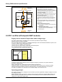
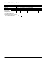
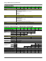
Galaxy 5000 technical specifications Current and protection characteristics Power rating Pn (kVA at PF = 0.8) (rated output apparent power) Active power (kW) Input currents 20 30 40 60 80 100 120 16 24 32 48 64 80 96 Currents and measurement conditions I1: current at normal AC input N.B. Currents are measured at: - full rated load, PF = 0.8 - rated voltage of normal AC source is 400 V - battery float charging. For normal AC-source rated voltages of 380 and 415 V, multiply the I1 and Iu values by 1.05 and 0.96 respectively. Iu: load current Ibmax: maximum battery current Fig 22. Input currents. Max. input current I1 (A) for 5 to 10 minutes 29 41 of backup time, battery recharging 53 Load current Iu (A) 29 44 58 Max. current supplied by battery Ibmax (A) 60 90 120 Battery protection using Schneider Electric circuit breakers is advised Battery protection Type (3P) NS100 NS100 NS100 Trip unit TM63D TM100D TM100D Mag. setting (A) 500 800 800 Thermal position 1 1 1 (1) Upstream protection using Schneider Electric circuit breakers is advised Separate normal and bypass AC inputs (2) Normal AC input (3P) Type (3P) Compact NS 125N, H or L Trip unit TMD125D (2) Bypass AC input (4P) Type (4P) Compact NS 125N, H or L Trip unit TMD125D 78 104 130 155 87 180 116 240 145 300 174 360 NS160 TM160D 800 1 NS160 TM160D 800 1 NS250 TM250D 1250 1 NS250 TM250D 1250 1 (2) Compact NS 250N, H or L TMD 250D (2) Compact NS 250N, H or L TMD 250D (1) Protection devices for single-UPS units, supplied with 400 V, 50 to 60 Hz, confirmation required. Check compliance with local standards and suitability for specific installation conditions, notably: withstand for short-circuit current at point of installation protection of static-switch semiconductors with respect to maximum permissible currents discrimination with UPS output protection devices in case of operation via the bypass. (2) Depending on the installation short-circuit current. MGE UPS SYSTEMS SPTC5 500 UK – 09/2005 page 28