1
MELDAS is a registered trademark of Mitsubishi Electric Corporation.
Other company and product names that appear in this manual are trademarks or registered
trademarks of their respective companies.
Introduction
Thank you for selecting the Mitsubishi numerical control unit.
This instruction manual describes the handling and caution points for using this AC
servo/spindle.
Incorrect handling may lead to unforeseen accidents, so always read this instruction
manual thoroughly to ensure correct usage.
Make sure that this instruction manual is delivered to the end user.
Always store this manual in a safe place.
All specifications for the MDS-C1-SPA Series are described in this manual. However,
each CNC may not be provided with all specifications, so refer to the specifications for
the CNC on hand before starting use.
Notes on Reading This Manual
(1) Since the description of this specification manual deals with NC in general, for the
specifications of individual machine tools, refer to the manuals issued by the
respective machine manufacturers. The "restrictions" and "available functions"
described in the manuals issued by the machine manufacturers have precedence
to those in this manual.
(2) This manual describes as many special operations as possible, but it should be
kept in mind that items not mentioned in this manual cannot be performed.
i
Precautions for safety
Please read this manual and auxiliary documents before starting installation, operation,
maintenance or inspection to ensure correct usage. Thoroughly understand the device, safety
information and precautions before starting operation.
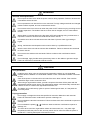
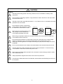
The safety precautions in this instruction manual are ranked as "WARNING" and "CAUTION".
DANGER
WARNING
CAUTION
When there is a potential risk of fatal or serious injuries if
handling is mistaken.
When operator could be fatally or seriously injured if handling
is mistaken.
When a dangerous situation may occur if handling is mistaken
leading to medium or minor injuries, or physical damage.
Note that some items described as
CAUTION may lead to major results depending on
the situation. In any case, important information that must be observed is described.
The numeric control unit is configured of the control unit, operation board, servo drive unit,
spindle drive unit, power supply, servomotor and spindle motor, etc.
In this section "Precautions for safety", the following items are generically called the "motor".
• Servomotor
• Spindle motor
In this section "Precautions for safety", the following items are generically called the "unit".
• Servo drive unit
• Spindle drive unit
• Power supply unit
ii
WARNING
1. Electric shock prevention
Do not open the front cover while the power is ON or during operation. Failure to observe this
could lead to electric shocks.
Do not operate the unit with the front cover removed. The high voltage terminals and charged
sections will be exposed, and can cause electric shocks.
Do not remove the front cover even when the power is OFF unless carrying out wiring work or
periodic inspections. The inside of the servo drive units is charged, and can cause electric
shocks.
Wait at least 15 minutes after turning the power OFF before starting wiring, maintenance or
inspections. Failure to observe this could lead to electric shocks.
Ground the servo drive unit and servomotor with Class C (former class 3) grounding or
higher.
Wiring, maintenance and inspection work must be done by a qualified technician.
Wire the servo drive unit and servomotor after installation. Failure to observe this could lead
to electric shocks.
Do not touch the switches with wet hands. Failure to observe this could lead to electric
shocks.
Do not damage, apply forcible stress, place heavy items on the cables or get them caught.
Failure to observe this could lead to electric shocks.
CAUTION
1. Fire prevention
Install the servo drive units, servomotors and regenerative resistor on noncombustible
material. Direct installation on combustible material or near combustible materials could lead
to fires.
Shut off the power on the servo drive unit side if the servo drive unit fails. Fires could be
caused if a large current continues to flow.
When using a regenerative resistor, provide a sequence that shuts off the power with the
regenerative resistor's error signal. The regenerative resistor could abnormally overheat and
cause a fire due to a fault in the regenerative transistor, etc.
The battery unit could heat up, ignite or rupture if submerged in water, or if the poles are
incorrectly wired.
2. Injury prevention
Do not apply a voltage other than that specified in Instruction Manual on each terminal.
Failure to observe this item could lead to ruptures or damage, etc.
Do not mistake the terminal connections. Failure to observe this item could lead to ruptures or
damage, etc.
Do not mistake the polarity ( + , – ). Failure to observe this item could lead to ruptures or
damage, etc.
The servo drive unit's fins, regenerative resistor and servomotor, etc., may reach high
temperatures while the power is ON, and may remain hot for some time after the power is
turned OFF. Touching these parts could result in burns.
iii
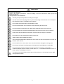
CAUTION
3. Various precautions
Observe the following precautions. Incorrect handling of the unit could lead to faults, injuries and
electric shocks, etc.
(1) Transportation and installation
Correctly transport the product according to its weight.
Use the servomotor's hanging bolts only when transporting the servomotor. Do not transport
the servomotor when it is installed on the machine.
Do not stack the products above the tolerable number.
Do not hold the cables, axis or detector when transporting the servomotor.
Do not hold the connected wires or cables when transporting the servo drive units.
Do not hold the front cover when transporting the servo drive units. The unit could drop.
Follow this Instruction Manual and install in a place where the weight can be borne.
Do not get on top of or place heavy objects on the unit.
Always observe the installation directions.
Secure the specified distance between the servo drive unit and control panel's inner wall, and
between other devices.
Do not install or run a servo drive unit or servomotor that is damaged or missing parts.
Do not block the intake or exhaust ports of the servomotor provided with a cooling fan.
Do not let foreign objects enter the servo drive units or servomotors. In particular, if
conductive objects such as screws or metal chips, etc., or combustible materials such as oil
enter, rupture or breakage could occur.
The servo drive units and servomotors are precision devices, so do not drop them or apply
strong impacts to them.
iv
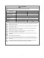
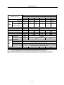
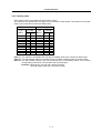
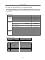
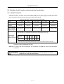
CAUTION
Store and use the units under the following environment conditions.
Environment
Ambient temperature
Ambient humidity
Storage temperature
Storage humidity
Atmosphere
Altitude
Vibration
Conditions
Servo drive unit
Servomotor
0°C to +55°C (with no freezing) 0°C to +40°C (with no freezing)
90%RH or less
80%RH or less
(with no dew condensation)
(with no dew condensation)
–15°C to +70°C
90%RH or less (with no dew condensation)
Indoors (where unit is not subject to direct sunlight),
with no corrosive gas, combustible gas, oil mist, or dust
1,000m or less above sea level
Follows each specifications
4.9m/s2 (0.5G) or less
manual
Securely fix the servomotor to the machine. Insufficient fixing could lead to the servomotor
slipping off during operation.
Always install the servomotor with reduction gear in the designated direction. Failure to do
so could lead to oil leaks.
Structure the rotary sections of the servomotor so that it can never be touched during
operation. Install a cover, etc., on the shaft.
When installing a coupling to a servomotor shaft end, do not apply an impact by
hammering, etc. The detector could be damaged.
Do not apply a load exceeding the tolerable load onto the servomotor shaft. The shaft
could break.
Store the motor in the package box.
When inserting the shaft into the built-in IPM motor, do not heat the rotor higher than
130°C. The magnet could be demagnetized, and the specifications characteristics will not
be ensured.
If the unit has been stored for a long time, always check the operation before starting
actual operation. Please contact the Service Center or Service Station.
v
CAUTION
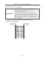
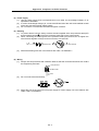
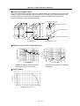
(2) Wiring
Correctly and securely perform the wiring. Failure to do so could lead to runaway of the
servomotor.
Do not install a condensing capacitor, surge absorber or radio noise filter on the output side
of the servo drive unit.
Correctly connect the output side (terminals U, V, W). Failure to do so could lead to abnormal
operation of the servomotor.
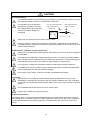
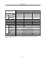
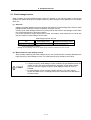
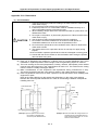
Do not directly connect a commercial
power supply to the servomotor. Failure
to observe this could result in a fault.
Servodrive unit
Servodrive unit
COM
(24VDC)
When using an inductive load such as a
relay, always connect a diode as a
noise measure parallel to the load.
Control output
signal
COM
(24VDC)
RA
Control output
signal
RA
When using a capacitance load such as a lamp, always connect a protective resistor as a
noise measure serial to the load.
Do not reverse the direction of a diode which connect to a DC relay for the control output
signals to suppress a surge. Connecting it backwards could cause the drive unit to
malfunction so that signals are not output, and emergency stop and other safety circuits are
inoperable.
Do not connect/disconnect the cables connected between the units while the power is ON.
Securely tighten the cable connector fixing screw or fixing mechanism. An insecure fixing
could cause the cable to fall off while the power is ON.
When using a shielded cable instructed in the connection manual, always ground the cable
with a cable clamp, etc.
Always separate the signals wires from the drive wire and power line.
Use wires and cables that have a wire diameter, heat resistance and flexibility that conforms
to the system.
vi
CAUTION
(3) Trial operation and adjustment
Check and adjust each program and parameter before starting operation. Failure to do so
could lead to unforeseen operation of the machine.
Do not make remarkable adjustments and changes as the operation could become unstable.
(4) Usage methods
Install an external emergency stop circuit so that the operation can be stopped and power
shut off immediately.
Turn the power OFF immediately if smoke, abnormal noise or odors are generated from the
servo drive unit or servomotor.
Unqualified persons must not disassemble or repair the unit.
Never make modifications.
Reduce magnetic damage by installing a noise filter. The electronic devices used near the
servo drive unit could be affected by magnetic noise.
Use the servo drive unit, servomotor and regenerative resistor with the designated
combination. Failure to do so could lead to fires or trouble.
The brake (magnetic brake) assembled into the servomotor are for holding, and must not be
used for normal braking.
There may be cases when holding is not possible due to the magnetic brake's life or the
machine construction (when ball screw and servomotor are coupled via a timing belt, etc.).
Install a stop device to ensure safety on the machine side.
After changing the programs/parameters or after maintenance and inspection, always test the
operation before starting actual operation.
Do not enter the movable range of the machine during automatic operation. Never place body
parts near or touch the spindle during rotation.
Follow the power supply specification conditions given in the separate specifications manual
for the power (input voltage, input frequency, tolerable sudden power failure time, etc.).
Set all bits to "0" if they are indicated as not used or empty in the explanation on the bits.
Do not use the dynamic brakes except during the emergency stop. Continuous use of the
dynamic brakes could result in brake damage.
If a breaker is shared by several power supply units, the breaker may not activate when a
short-circuit fault occurs in a small capacity unit. This is dangerous, so never share the
breakers.
vii
CAUTION
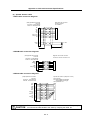
(5) Troubleshooting
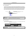
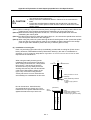
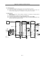
If a hazardous situation is predicted during power failure or product trouble, use a servomotor
with magnetic brakes or install an external brake mechanism.
Use a double circuit configuration
that allows the operation circuit for
the magnetic brakes to be operated
even by the external emergency
stop signal.
Shut off with the servomotor
brake control output.
Servomotor
MBR
Shut off with NC brake
control PLC output.
EMG
Magnetic
brake
24VDC
Always turn the input power OFF when an alarm occurs.
Never go near the machine after restoring the power after a power failure, as the machine
could start suddenly. (Design the machine so that personal safety can be ensured even if the
machine starts suddenly.)
(6) Maintenance, inspection and part replacement
Always carry out maintenance and inspection after backing up the servo drive unit's programs
or parameters.
The capacity of the electrolytic capacitor will drop over time. To prevent secondary disasters
due to failures, replacing this part every five years when used under a normal environment is
recommended. Contact the Service Center or Service Station for replacement.
Do not perform a megger test (insulation resistance measurement) during inspections.
If the battery low warning is issued, save the machining programs, tool data and parameters
with an input/output unit, and then replace the battery.
Do not short circuit, charge, overheat, incinerate or disassemble the battery.
(7) Disposal
Dispose of this unit as general industrial waste. Note that MDS Series unit with a heat
dissipating fin protruding from the back of the unit contains substitute Freon. Do not dispose
of this type of unit as general industrial waste. Always return to the Service Center or Service
Station.
Do not disassemble the servo drive unit or servomotor parts.
Dispose of the battery according to local laws.
(8) General precautions
The drawings given in this Specifications and Maintenance Instruction Manual show the covers and
safety partitions, etc., removed to provide a clearer explanation. Always return the covers or partitions
to their respective places before starting operation, and always follow the instructions given in this
manual.
viii
CONTENTS
1. Introduction
1-1 Spindle drive system configuration................................................................................................... 1-2
1-1-1 System configuration ................................................................................................................. 1-2
1-1-2 Unit outline type ......................................................................................................................... 1-3
1-2 Explanation of type ........................................................................................................................... 1-4
1-2-1 Spindle motor type ..................................................................................................................... 1-4
1-2-2 Spindle drive unit type ............................................................................................................... 1-5
1-2-3 Power supply unit type............................................................................................................... 1-6
1-2-4 AC reactor type .......................................................................................................................... 1-7
2. Specifications
2-1 Spindle motor.................................................................................................................................... 2-2
2-1-1 Specifications............................................................................................................................. 2-2
2-1-2 Output characteristics ................................................................................................................ 2-7
2-2 Drive unit......................................................................................................................................... 2-12
2-2-1 Installation environment conditions.......................................................................................... 2-12
2-2-2 Spindle drive unit ..................................................................................................................... 2-12
2-2-3 Power supply unit..................................................................................................................... 2-17
2-2-4 AC reactor................................................................................................................................ 2-18
2-2-5 D/A output specifications for spindle drive unit........................................................................ 2-19
2-2-6 Explanation of each part .......................................................................................................... 2-20
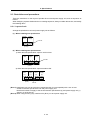
2-3 Restrictions and precautions .......................................................................................................... 2-22
2-3-1 Layout of unit ........................................................................................................................... 2-22
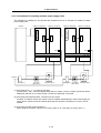
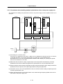
2-3-2 Precautions for installing multiple power supply units ............................................................. 2-23
2-3-3 Precautions when installing multiple spindle drive units to one power supply unit ................. 2-24
3. Characteristics
3-1 Spindle motor.................................................................................................................................... 3-2
3-1-1 Environmental conditions........................................................................................................... 3-2
3-1-2 Shaft characteristics................................................................................................................... 3-2
3-2 Drive unit characteristics................................................................................................................... 3-3
3-2-1 Environmental conditions........................................................................................................... 3-3
3-2-2 Heating value ............................................................................................................................. 3-4
4. Dedicated Options
4-1 Orientation option ............................................................................................................................. 4-2
4-1-1 Magnetic sensor......................................................................................................................... 4-3
4-1-2 Spindle side detector (OSE-1024-3-15-68, OSE-1024-3-15-68-8) ........................................... 4-6
4-2 Cables and connectors ..................................................................................................................... 4-8
4-2-1 Cable connection diagram ......................................................................................................... 4-8
4-2-2 List of cables and connectors .................................................................................................... 4-9
5. Peripheral Devices
5-1 Selection of wire ............................................................................................................................... 5-2
5-1-1 Example of wires by unit............................................................................................................ 5-2
5-2 Selection the AC reactor, contactor and no-fuse breaker ................................................................ 5-4
5-2-1 Standard selection ..................................................................................................................... 5-4
5-2-2 Selection of contactor for changing over spindle motor drive wire ............................................ 5-5
5-3 Earth leakage breaker ...................................................................................................................... 5-6
5-4 Branch-circuit protection ................................................................................................................... 5-7
5-4-1 Circuit protector.......................................................................................................................... 5-7
5-4-2 Fuse protection .......................................................................................................................... 5-7
5-5 Noise filter......................................................................................................................................... 5-8
5-6 Surge absorber ................................................................................................................................. 5-9
5-7 Speedometer and load meter ......................................................................................................... 5-10
5-8 Cable for peripheral control ............................................................................................................ 5-11
5-8-1 Cable for external emergency stop.......................................................................................... 5-11
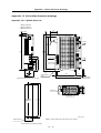
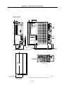
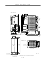
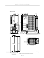
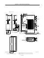
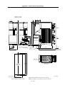
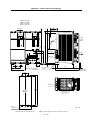
Appendix 1. Outline Dimension Drawings
Appendix 1-1 Outline dimension drawings of spindle motor.................................................................A1-2
Appendix 1-1-1 SJ Series..................................................................................................................A1-2
Appendix 1-1-2 SJ-V Series..............................................................................................................A1-5
Appendix 1-1-3 SJ-VS Series .........................................................................................................A1-15
Appendix 1-2 Unit outline dimension drawings...................................................................................A1-17
Appendix 1-2-1 Spindle drive unit ...................................................................................................A1-17
Appendix 1-2-2 Power supply unit ..................................................................................................A1-21
Appendix 1-2-3 AC rector................................................................................................................A1-25
Appendix 2. Cable and Connector Specifications
Appendix 2-1 Selection of cable ...........................................................................................................A2-2
Appendix 2-1-1 Cable wire and assembly.........................................................................................A2-2
Appendix 2-2 Cable connection diagram..............................................................................................A2-4
Appendix 2-3 Connector outline dimension drawings ..........................................................................A2-8
Appendix 3. Selection
Appendix 3-1 Selecting the power supply.............................................................................................A3-2
Appendix 3-1-1 Selecting according to the continuous rated capacity .............................................A3-2
Appendix 3-1-2 Selection example ...................................................................................................A3-3
Appendix 4. Explanation of Large Capacity Spindle Unit Specifications
Appendix 4-1 Explanation of large capacity spindle unit specifications ...............................................A4-2
Appendix 4-1-1 Outline......................................................................................................................A4-2
Appendix 4-1-2 List of units...............................................................................................................A4-2
Appendix 4-1-3 Selection of AC reactor (B-AL), contactor and NFB ................................................A4-2
Appendix 4-1-4 Outline dimension drawings.....................................................................................A4-3
Appendix 4-1-5 Panel cut dimension drawing...................................................................................A4-8
Appendix 4-1-6 Heating value...........................................................................................................A4-9
Appendix 4-1-7 Selecting the power capacity ...................................................................................A4-9
Appendix 4-1-8 Selecting the wire size .............................................................................................A4-9
Appendix 4-1-9 Drive unit connection screw size ...........................................................................A4-10
Appendix 4-1-10 Connecting each unit ...........................................................................................A4-10
Appendix 4-1-11 Restrictions ..........................................................................................................A4-12
Appendix 4-1-12 Parameters ..........................................................................................................A4-14
Appendix 4-1-13 Precautions..........................................................................................................A4-14
Appendix 5. Explanation of Small Capacity Spindle Drive Unit Specifications
Appendix 5-1 Explanation of small capacity spindle drive unit specifications ......................................A5-2
Appendix 5-1-1 Outline......................................................................................................................A5-2
Appendix 5-1-2 List of units...............................................................................................................A5-2
Appendix 5-1-3 Outline dimension drawings.....................................................................................A5-2
Appendix 5-1-4 Drive unit specifications list......................................................................................A5-4
Appendix 5-1-5 Heating value...........................................................................................................A5-5
Appendix 5-1-6 Selecting the wire size .............................................................................................A5-5
Appendix 5-1-7 Drive unit connection screw size .............................................................................A5-5
Appendix 5-1-8 Restrictions ..............................................................................................................A5-6
Appendix 6. Compliance to EU EC Directives
Appendix 6-1 Compliance to EC Directives..........................................................................................A6-2
Appendix 6-1-1 European EC Directives ..........................................................................................A6-2
Appendix 6-1-2 Cautions for EC Directive compliance .....................................................................A6-2
Appendix 7. EMC Installation Guidelines
Appendix 7-1 Introduction .....................................................................................................................A7-2
Appendix 7-2 EMC instructions ............................................................................................................A7-2
Appendix 7-3 EMC measures ...............................................................................................................A7-3
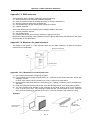
Appendix 7-4 Measures for panel structure..........................................................................................A7-3
Appendix 7-4-1 Measures for control panel unit ...............................................................................A7-3
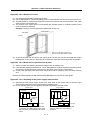
Appendix 7-4-2 Measures for door....................................................................................................A7-4
Appendix 7-4-3 Measures for operation board panel........................................................................A7-4
Appendix 7-4-4 Shielding of the power supply input section ............................................................A7-4
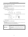
Appendix 7-5 Measures for various cables...........................................................................................A7-5
Appendix 7-5-1 Measures for wiring in panel....................................................................................A7-5
Appendix 7-5-2 Measures for shield treatment .................................................................................A7-5
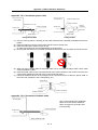
Appendix 7-5-3 Servomotor power cable..........................................................................................A7-6
Appendix 7-5-4 Servomotor feedback cable .....................................................................................A7-6
Appendix 7-5-5 Spindle motor power cable ......................................................................................A7-7
Appendix 7-5-6 Spindle motor feedback cable .................................................................................A7-7
Appendix 7-6 EMC countermeasure parts............................................................................................A7-8
Appendix 7-6-1 Shield clamp fitting...................................................................................................A7-8
Appendix 7-6-2 Ferrite core ..............................................................................................................A7-9
Appendix 7-6-3 Power line filter ......................................................................................................A7-10
Appendix 7-6-4 Surge protector ......................................................................................................A7-15
Appendix 8. Instruction Manual for Compliance with UL/c-UL Standard
Appendix 8 Instruction Manual for Compliance with UL/c-UL Standard...............................................A8-2
Appendix 9. Compliance with China Compulsory Product Certification (CCC Certification) System
Appendix 9-1 Outline of China Compulsory Product Certification System...........................................A9-2
Appendix 9-2 First Catalogue of Products subject to Compulsory Product Certification .....................A9-2
Appendix 9-3 Precautions for Shipping Products .................................................................................A9-3
Appendix 9-4 Application for Exemption...............................................................................................A9-4
Appendix 9-5 Mitsubishi NC Product Subject to/Not Subject to CCC Certification ..............................A9-5
1. Introduction
1-1 Spindle drive system configuration .................................................................................................... 1-2
1-1-1 System configuration................................................................................................................... 1-2
1-1-2 Unit outline type........................................................................................................................... 1-3
1-2 Explanation of type............................................................................................................................. 1-4
1-2-1 Spindle motor type ...................................................................................................................... 1-4
1-2-2 Spindle drive unit type ................................................................................................................. 1-5
1-2-3 Power supply unit type ................................................................................................................ 1-6
1-2-4 AC reactor type ........................................................................................................................... 1-7
1-1
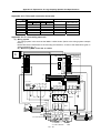
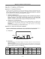
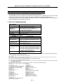
1. Introduction
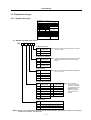
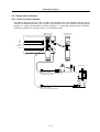
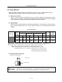
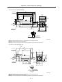
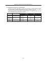
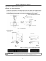
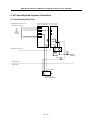
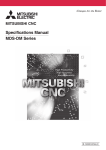
1-1 Spindle drive system configuration
1-1-1 System configuration
Spindle drive unit
(MDS-C1-SPA)
Power supply unit
(MDS-C1-CV)
Terminator
• NC
• Sequencer
• DIO device
• Meter
Breaker
or
fuse
(Note)
Prepared by
user
Contactor
(Note)
Prepared by
user
AC reactor
(B-AL)
Spindle motor
NFB
(Note)
Prepared by
user
Magnesensor or
spindle side detector (1024p/rev encoder)
1-2
3-phase 200VAC power supply
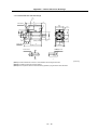
1. Introduction
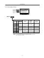
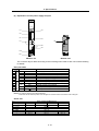
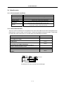
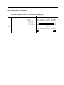
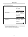
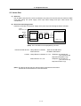
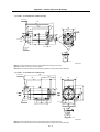
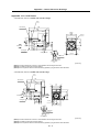
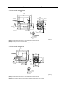
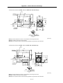
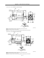
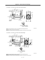
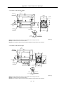
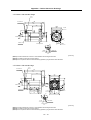
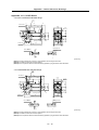
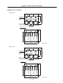
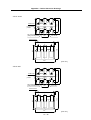
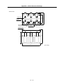
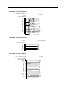
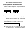
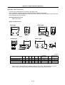
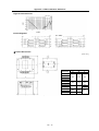
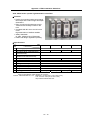
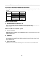
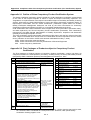
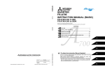
1-1-2 Unit outline type
Unit outline
type
B1
C1
Fin
D:260
Outline
dimensions
[mm]
H:380
D:260
/263
200
H:380
W:90
Heat dissipation method
Fin
Fin
D:260
200
D1/D2
200
H:380
W:120
W:150
Wiring allowance at front: 50mm
Required ventilation space at back:
15mm
Wiring allowance at front: 50mm
Required ventilation space at back:
15mm
Wiring allowance at front: 50mm
Required ventilation space at back:
15mm (D2: 12mm)
Heat radiated outside panel
(forced wind cooling)
Heat radiated outside panel
(forced wind cooling)
Heat radiated outside panel
(forced wind cooling)
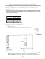
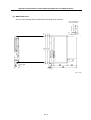
(Note) Refer to "Appendix 1 Outline dimension drawings" for detailed outline drawings.
For customers switching from MDS-A/B Series
The MDS-C1-SPA Series incorporates a highly efficient heat dissipating structure, so the depth of the fin
section is smaller than the MDS-A/B Series. Units with an "S" at the end of the type have a smaller unit
width than the MDS-A/B Series.
When designing the control panel with these unit outline dimensions, it may not be possible to mount the
conventional drive unit.
1-3
1. Introduction
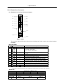
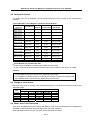
1-2 Explanation of type
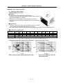
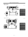
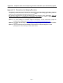
1-2-1 Spindle motor type
MITSUBISHI AC SPINDLE MOTOR
SJ-V5. 5-01
TYPE
SI CONT
4 POLE
3 PHASES
kW
r/min
A(~)
max
WIND
CONNECT
3.7
1500-6000
25
P OW ER FAC TOR
17
MOTOR INPUT(~)
137 162 V
2.8
S2
8000
30 min
S3
50 %
A(~)
max
U
82 %
kW
r/min
5.5
1500-6000
33
AMP INPUT(~)
200-230V 50/60Hz
4.1
8000
23
INSULATION CLASS F
AMB TEMP. 0-40ºC
SERIAL
DATE
FRAME
D90F
WEIGHT 49 kg
IEC 34-1 1994
IP
44
SPEC No.RSV00023*
MITSUBISHI ELECTRIC CORPORATION
MADE IN JAPAN
A19103-01
995291-01
Rating nameplate
(1) Standard spindle motor series
SJ-
(1)
(2)
(3) (4) (5)
(5) Z-phase detection
SymZ-phase
bol
presences
(Note) Presence of the Z-phase applies only to the SJ
and SJ-V Series.
None
No Z-phase
M
Z-phase present
(4) Special specifications
SymSpecial
(Note) A number indicating the constant output range is
bol
specifications
indicated after the symbol for the wide range
output.
None
None
Z
W
High-speed
Wide-range
constant output
(3) Base speed
SymBase speed
bol
A
B
L
X
(Note) The SJ-V Series is indicated with a specification
code (–01 to –99).
1500r/min
1150r/min
5000r/min
Special
(2) Short time rated output
SymShort time
Symbol
rated output
bol
2.2
3.7
5.5
7.5
11
15
18.5
2.2kW
3.7kW
5.5kW
7.5kW
11kW
15kW
18.5kW
(1) Motor series
Symbol
None
V
VS
Short time
rated output
22
26
30
37
45
55
22kW
26kW
30kW
37kW
45kW
55kW
(Note) The 3.7kW and
smaller or the 37kW
and larger capacities
are available with the
MDS-B-SP Series.
Refer to Appendix 4
and Appendix 5 for
details.
Motor series
Large capacity
Compact medium to large capacity
Hollow shaft
(Note) Refer to the "MELDAS AC Spindle Built-in Series Standard Specifications" (BFN-14118-04) for
details on the built-in spindle motor.
1-4
1. Introduction
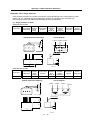
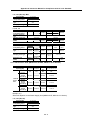
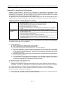
1-2-2 Spindle drive unit type
MITSUBISHI
Motor type
SERVO DRIVE UNIT
MDS-C1-SPA-55
TYPE
POWER 5.5kW
INPUT 20A DC270-311V
0.2A 1PH 200/200-230V 50/60Hz
OUTPUT 18A 3PH 155V 0-240Hz
MANUAL# IB-1500148
S/W BNDXXXXXXXXX H/W VER. *
SERIAL# XXXXXXXXXXX
DATE 00/01
MITSUBISHI ELECTRIC CORPORATION JAPAN
Rated input
Rated output
Current state
Serial No.
*
X
X
X
X
X
X
X
X
X
X
X
*
Rating nameplate
MDS-C1- (1) - (2)
-
(3)
(3) Option
Symbol
None
Compatible optional function
None
R
Orientation function
D
Digital speed command input function
T
S-analog synchronous tapping function
RD
Orientation function and digital speed command input function
RT
Orientation function and S-analog synchronous tapping function
(2) Capacity
Symbol
Capa-
Outline type
city
(unit width)
(Note) The 3.7kW and smaller or
the 37kW and larger
capacities are available
(kW)
with the MDS-B-SP
55
5.5
75
7.5
110
11
150
15
C1
185
18.5
(120mm wide)
220
22
260
26
D2
300
30
(150mm wide)
B1
(90mm wide)
Series.
Refer to Appendix 4 and
Appendix 5 for details.
D1
(150mm wide)
(1) Spindle drive unit series
Compatible motor rotation
Symbol
speed
SPA
Less than 10,000r/min
SPAH
10,000r/min or more
Details
Standard specifications
(Note 1) The 3.7kW and smaller or the 37kW and larger capacities are available with the MDS-B-SP
Series. Refer to Appendix 4 and Appendix 5 for details.
(Note 2) The Outline of unit is determined according to symbol in the above table “(2)” and it is not
affected by the above table “(3)”.
1-5
1. Introduction
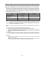
1-2-3 Power supply unit type
POWER SUPPLY UNIT
MDS-C1-CV-150
TYPE
POWER 15kW
INPUT 49A 3PH 200/200-230V 50/60Hz
0.2A 1PH 200/200-230V 50/60Hz
OUTPUT 58A DC270-311V
3040
DIN VDE0160 MANUAL# BNP-C3000
MITSUBISHI
Motor type
Rated input
Rated output
Current state
Serial No.
S/W BND538W000A1 H/W VER. D
SERIAL# XXXXXXXXXXX DATE 02/09
MITSUBISHI ELECTRIC CORPORATION JAPAN
*
X
X
X
X
X
X
X
X
X
X
X
*
Rating nameplate
MDS-C1-
(1)
Power supply unit
(1) Motor Capatype
city Outline type
(unit width)
(kW)
MDS-C1CV-37
3.7
CV-55
5.5
CV-75
7.5
CV-110
11
CV-150
CV-185
15
A2
(60mm wide)
B1
(90mm wide)
C1
18.5 (120mm wide)
CV-220
22
CV-260
26
D1
CV-300
30
(150mm wide)
CV-370
37
Compatible AC
reactor
Compatible
contactor
(Mitsubishi)
(Note 1)
Compatible NFB
(Mitsubishi)
(Note 1)
B-AL-7.5K
S-N25 200VAC
NF50CS3P-40A05
B-AL-11K
S-N35 200VAC
NF50CS3P-50A05
B-AL-18.5K
S-N50 200VAC
NF100CS3P-100A05
B-AL-30K
S-N80 200VAC
NF225CS3P-150A05
B-AL-37K
S-N150 200VAC
NF225CS3P-175A05
(Note 1) This is an optional part, and must be prepared by the user.
(Note 2) The 45kW and larger capacities are available with the MDS-B-CVE Series.
Refer to Appendix 4 for details.
1-6
1. Introduction
1-2-4 AC reactor type
Type
B-AL-7.5K
Nameplate
Top surface of AC reactor
B-AL-
(1)
AC reactor
Motor
Capatype
city
(kW)
B-AL-
Compatible
power supply unit
MDS-C1-CV-37
7.5K
7.5
MDS-C1-CV-55
MDS-C1-CV-75
11K
18.5K
11
18.5
MDS-C1-CV-110
MDS-C1-CV-150
MDS-C1-CV-185
MDS-C1-CV-220
30K
30
MDS-C1-CV-260
MDS-C1-CV-300
37K
37
MDS-C1-CV-370
1-7
2. Specifications
2-1 Spindle motor ..................................................................................................................................... 2-2
2-1-1 Specifications .............................................................................................................................. 2-2
2-1-2 Output characteristics.................................................................................................................. 2-7
2-2 Drive unit .......................................................................................................................................... 2-12
2-2-1 Installation environment conditions ........................................................................................... 2-12
2-2-2 Spindle drive unit....................................................................................................................... 2-12
2-2-3 Power supply unit ...................................................................................................................... 2-17
2-2-4 AC reactor ................................................................................................................................. 2-18
2-2-5 D/A output specifications for spindle drive unit ......................................................................... 2-19
2-2-6 Explanation of each part............................................................................................................ 2-20
2-3 Restrictions and precautions............................................................................................................ 2-22
2-3-1 Layout of unit ............................................................................................................................. 2-22
2-3-2 Precautions for installing multiple power supply units............................................................... 2-23
2-3-3 Precautions when installing multiple spindle drive units to one power supply unit................... 2-24
2-1
2. Specifications
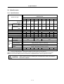
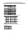
2-1 Spindle motor
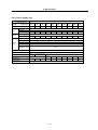
2-1-1 Specifications
Base rotation speed
1500r/min Series
Spindle motor type
SJ-V
Compatible spindle drive unit type
MDS-B/C1Continuous rating
[kW]
Output
30-minute rating
capacity
50%ED rating
[kW]
Base speed
[r/min]
Maximum speed
[r/min]
Frame No.
Continuous rated torque [N·m]
GD2
[kg·m2]
Inertia
[kg·m2]
Tolerable radial load
[N]
Input voltage
Cooling
Maximum power
fan
consumption
Ambient temperature
Environment
Ambient humidity
Atmosphere
Altitude
Weight
Insulation
[kg]
2.2-01
3.7-01
5.5-01
7.5-01
11-01
15-01
18.5-01
22-01
26-01
MDS-BSPAH22
MDS-BSPAH37
SPA-55
SPA-75
SPA110
SPA150
SPA185
SPA220
SPA300
1.5
2.2
3.7
5.5
7.5
11
15
18.5
22
2.2
3.7
5.5
7.5
11
15
18.5
22
26
1500
10000
8000
A90
B90
D90
A112
B112
9.5
14.0
23.5
35.0
47.7
0.027
0.035
0.059
0.098
0.12
0.007
0.009
0.015
0.025
0.03
980
1470
1960
Single-phase 200V
42W
40W
6000
A160
70.0
0.23
0.06
95.5
0.23
0.06
B160
118
0.32
0.08
2940
C160
140
0.38
0.10
3-phase 200V
63W
Operation: 0 to 40°C (non freezing), Storage: –20 to 65°C (non freezing)
Operation: 90%RH or less (non condensing),
Storage: 90%RH or less (non condensing)
Indoors (no direct sunlight); no corrosive gas, inflammable gas, oil mist, or dust
Operation: 1000 meters or less above sea level,
Storage: 1000 meters or less above sea level
25
30
49
60
70
110
135
155
Class F
(Note 1) The rated output is guaranteed at the rated input voltage (200/220/230VAC) to the power supply unit.
If the input voltage fluctuates and drops below 200VAC, the rated output may not be attained.
(Note 2) The 50%ED rating applies for a 10-minute cycle time consisting of ON for five minutes and OFF for five minutes.
(Note 3) The 3.7kW and smaller capacities are available with the MDS-B-SPA Series. Refer to Appendix 5 for details.
CAUTION
When replacing the SJ-V series by the conventional SJ series, the shorter L
dimension is applied.
2-2
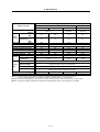
2. Specifications
Large capacity series
Spindle motor type
SJ30A
Compatible spindle drive unit type
MDS-BContinuous rating
[kW]
Output
30-minute rating
capacity
50%ED rating
[kW]
Base speed
[r/min]
Maximum speed
[r/min]
Frame No.
Continuous rated torque [N·m]
GD2
[kg·m2]
Inertia
[kg·m2]
Tolerable radial load
[N]
Input voltage
Cooling
Maximum power
fan
consumption
Ambient temperature
Environment
Ambient humidity
Atmosphere
Altitude
Weight
Insulation
[kg]
37BP
SPA-370
SJ-V
45BP
55-01
SPA-450
SPA-550
22
30
37
45
30
37
45
55
1500
4500
B160
B180
140
249
0.69
1.36
0.17
0.34
2940
4900
Single-phase 200V
1150
3450
A200
307
2.19
0.55
5880
A225
374
3.39
0.85
5880
130W
60W
3-phase 200V
115W
Operation: 0 to 40°C (non freezing), Storage: –20 to 65°C (non freezing)
Operation: 90%RH or less (non condensing),
Storage: 90%RH or less (non condensing)
Indoors (no direct sunlight); no corrosive gas, inflammable gas, oil mist, or dust
Operation: 1000 meters or less above sea level,
Storage: 1000 meters or less above sea level
200
300
390
450
Class F
(Note 1) The rated output is guaranteed at the rated input voltage (200/220/230VAC) to the power supply unit.
If the input voltage fluctuates and drops below 200VAC, the rated output may not be attained.
(Note 2) The 50%ED rating applies for a 10-minute cycle time consisting of ON for five minutes and OFF for five minutes.
(Note 3) The 37kW and larger capacities are available with the MDS-B-SPA Series. Refer to Appendix 4 for details.
2-3
2. Specifications
Wide range constant
output series
Wide range (1:8) constant output series
Spindle motor type
SJ-V
11-01
Compatible spindle drive unit type
MDS-C1Continuous rating
[kW]
Output
capacity 30-minute rating
50%ED rating [kW]
Base speed
[r/min]
Maximum speed
Frame No.
Continuous rated torque
GD2
Inertia
Tolerable radial load
[r/min]
Cooling
fan
Environment
[N·m]
[kg·m2]
[kg·m2]
[N]
SPA-110
SJ-
15-03
18.5-03
22-05
22XW5
22XW8
SPA-185
SPA-220
SPA-260
SPA-300
SPA-300
3.7
5.5
7.5
9
11
19.5
18.5
5.5
7.5
9
11
15
22
22
140
0.32
0.08
600
(800)
5000
B180
239
1.36
0.34
3920
Singlephase
200V
550
(600)
4000
A200
294
2.19
0.55
5880
750
6000
B112
47.1
0.12
0.03
1960
Input voltage
A160
70.0
0.23
0.06
B160
95.5
0.23
0.06
115
0.32
0.08
2940
3-phase 200V
Maximum power
consumption
Ambient temperature
Ambient humidity
Atmosphere
Altitude
Weight
Insulation
11-09
[kg]
40W
63W
180W
3-phase
200V
60W
Operation: 0 to 40°C (non freezing), Storage: –20 to 65°C (non freezing)
Operation: 90%RH or less (non condensing),
Storage: 90%RH or less (non condensing)
Indoors (no direct sunlight); no corrosive gas, inflammable gas, oil mist, or dust
Operation: 1000 meters or less above sea level,
Storage: 1000 meters or less above sea level
70
110
135
300
390
Class F
(Note 1) The rated output is guaranteed at the rated input voltage (200/220/230VAC) to the power supply unit.
If the input voltage fluctuates and drops below 200VAC, the rated output may not be attained.
(Note 2) The 50%ED rating applies for a 10-minute cycle time consisting of ON for five minutes and OFF for five minutes.
2-4
2. Specifications
High-speed series
Spindle motor type
Compatible spindle drive unit type
MDS-B/C1Continuous rating
[kW]
Output
30-minute
rating
capacity
50%ED rating
[kW]
Base speed
[r/min]
Maximum speed
Frame No.
[r/min]
SJ-V
3.7-02ZM
7.5-03ZM
11-06ZM
11-08ZM
22-06ZM
30-02ZM
MDS-BSPAH-37
SPAH-110
SPAH-150
SPA-185
SPA-220
SPA-300
2.2
5.5
5.5
7.5
11
18.5
3.7
(15min. rating)
7.5
7.5
11
15
22
3000
1500
15000
12000
A90
A112
8000
B112
A160
B160
7.0
35.0
35.0
47.7
70.0
118
[kg·m2]
0.027
0.098
0.098
0.12
0.23
0.32
Inertia
[kg·m2]
0.007
0.025
0.03
0.06
Tolerable radial load
[N]
Continuous rated torque [N·m]
GD2
Cooling
fan
490
Maximum power
consumption
0.08
1960
3-phase 200V
42W
40W
63W
Operation: 0 to 40°C (non freezing), Storage: –20 to 65°C (non freezing)
Operation: 90%RH or less (non condensing),
Storage: 90%RH or less (non condensing)
Ambient humidity
Indoors (no direct sunlight); no corrosive gas, inflammable gas, oil mist, or dust
Atmosphere
Operation: 1000 meters or less above sea level,
Storage: 1000 meters or less above sea level
Altitude
Weight
Insulation
1470
Single-phase
200V
Input voltage
Ambient temperature
Environment
0.025
980
[kg]
25
60
70
125
155
Class F
(Note 1) The rated output is guaranteed at the rated input voltage (200/220/230VAC) to the power supply unit.
If the input voltage fluctuates and drops below 200VAC, the rated output may not be attained.
(Note 2) The 50%ED rating applies for a 10-minute cycle time consisting of ON for five minutes and OFF for five minutes.
(Note 3) The 3.7kW and smaller capacities are available with the MDS-B-SPA Series. Refer to Appendix 5 for details.
2-5
2. Specifications
Hollow shaft series
Spindle motor type
Compatible spindle drive unit type
MDS-C1Continuous rating
[kW]
Output
30-minute rating
capacity
50%ED rating
[kW]
Base speed
[r/min]
Maximum speed
[r/min]
Frame No.
Continuous rated torque [N·m]
GD2
[kg·m2]
Inertia
[kg·m2]
Tolerable radial load
[N]
Input voltage
Cooling
Maximum power
fan
consumption
SJ-VS
7.5-03ZM
22-06ZM
30-02ZM
SPAH-110
SPA-220
SPA-300
5.5
11
18.5
7.5
15
22
1500
12000
A112
35.0
0.099
0.025
0 (Note 3)
Single-phase 200V
40W
Ambient temperature
Environment
Ambient humidity
Atmosphere
Altitude
Weight
Insulation
[kg]
65
1500
8000
A160
70.0
0.23
0.058
0 (Note 3)
B160
118
0.32
0.08
0 (Note 3)
3-phase 200V
40W
Operation: 0 to 40°C (non freezing),
Storage: –20 to 65°C (non freezing)
Operation: 90%RH or less (non condensing),
Storage: 90%RH or less (non condensing)
Indoors (no direct sunlight); no corrosive
gas, inflammable gas, oil mist, or dust
Operation: 1000 meters or less above sea level,
Storage: 1000 meters or less above sea level
115
Class F
140
(Note 1) The rated output is guaranteed at the rated input voltage (200 to 230VAC) to the power supply unit.
(Note 2) The 50%ED rating applies for a 10-minute cycle time consisting of ON for five minutes and OFF for five minutes.
(Note 3) Do not apply a radial load.
2-6
2. Specifications
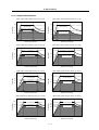
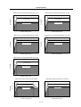
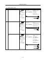
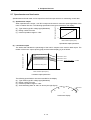
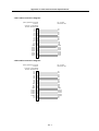
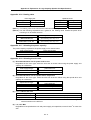
2-1-2 Output characteristics
[Base rotation speed 1500r/min series SJ-V2.2-01]
[Base rotation speed 1500r/min series SJ-V3.7-01]
3.7
2.2
Output [kW]
Output [kW]
15-minute rating
1.5
Continuous rating
1.3
0.9
15-minute rating
2.2
Continuous rating
1.3
0
0
1500
6000
0
10000
1500
6000
Rotation speed [r/min]
[Base rotation speed 1500r/min series SJ-V5.5-01]
[Base rotation speed 1500r/min series SJ-V7.5-01]
7.5
4.1
3.7
15-minute rating
Output [kW]
15-minute rating
Continuous rating
2.8
0
0
1500
6000
5.5
Continuous rating
4.1
0
8000
0
1500
6000
Rotation speed [r/min]
[Base rotation speed 1500r/min series SJ-V11-01]
[Base rotation speed 1500r/min series SJ-V15-01]
15
15-minute rating
Output [kW]
Output [kW]
15-minute rating
8.3
7.5
Continuous rating
5.6
0
1500
4500
11
Continuous rating
8.3
0
6000
0
1500
6000
Rotation speed [r/min]
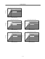
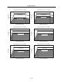
[Base rotation speed 1500r/min series SJ-V18.5-01]
[Base rotation speed 1500r/min series SJ-V22-01]
22
15-minute rating
15-minute rating
15
13.9
Output [kW]
Output [kW]
4500
Rotation speed [r/min]
18.5
Continuous
11.3
0
8000
Rotation speed [r/min]
11
0
10000
Rotation speed [r/min]
5.5
Output [kW]]
0
0
1500
4500
6000
18.5
16.5
13.9
0
Rotation speed [r/min]
Continuous rating
0
1500
4500
Rotation speed [r/min]
2-7
6000
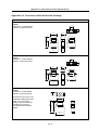
2. Specifications
[Base rotation speed 1500r/min series SJ-V26-01]
26
Output [kW]
30-minute rating
22
Continuous rating
0
0
1500
6000
Rotation speed [r/min]
[Large capacity series SJ-30A]
[Large capacity series SJ-37BP]
30
37
30-minute rating
Output [kW]
Output [kW]
30-minute rating
22
Continuous rating
0
0
1500
30
Continuous rating
0
4500
0
1150
Rotation speed [r/min]
[Large capacity series SJ-45BP]
[Large capacity series SJ-V55-01]
55
45
30-minute rating
37
Output [kW]
Output [kW]
30-minute rating
Continuous rating
0
3450
Rotation speed [r/min]
0
1150
45
Continuous
0
3450
0
1150
Rotation speed [r/min]
Rotation speed [r/min]
2-8
3450
2. Specifications
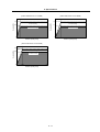
[Wide range (1:8) constant output series SJ-V11-01]
[Wide range (1:8) constant output series SJ-V11-09]
5.5
7.5
30-minute rating
Output [kW]
Output [kW]
30-minute rating
3.7
Continuous rating
0
0
750
5.5
Continuous rating
0
6000
0
750
Rotation speed [r/min]
[Wide range (1:8) constant output series SJ-V15-03]
[Wide range (1:8) constant output series SJ-V18.5-03]
9
11
30-minute rating
7.5
Output [kW]
Output [kW]
30-minute rating
Continuous rating
0
6000
Rotation speed [r/min]
0
750
9
Continuous rating
0
6000
0
6000
750
Rotation speed [r/min]
Rotation speed [r/min]
[Wide range (1:8) constant output series SJ-V22-05]
15
Output [kW]
30-minute rating
11
Continuous rating
0
0
750
6000
Rotation speed [r/min]
[Wide range constant output series SJ-22XW8]
[Wide range constant output series SJ-22XW5]
22
22
30-minute rating
Output [kW]
30-minute rating
19.5
13
11.5
0
18.5
Continuous rating
Continuous rating
0
600 800
3000
5000
Rotation speed [r/min]
0
0
4000
500 600
Rotation speed [r/min]
2-9
2. Specifications
[High speed series SJ-V7.5-03ZM]
[High speed series SJ-V3.7-02ZM]
3.7
7.5
3
2.2
1.8
0
Continuous rating
0
3000
12000
15-minute rating
6.3
5.5
Output [kW]
Output [kW]
15-minute rating
4.6
0
15000
Continuous rating
0
1500
10000
Rotation speed [r/min]
Rotation speed [r/min]
[High speed series SJ-V11-06ZM]
[High speed series SJ-V11-08ZM]
11
7.5
30-minute rating
Output [kW]
Output [kW]
30-minute rating
5.5
Continuous rating
0
0
1500
7.5
Continuous rating
0
12000
1500
8000
Rotation speed [r/min]
[High speed series SJ-V22-06ZM]
[High speed series SJ-V30-02ZM]
22
30-minute rating
Output [kW]
30-minute rating
Output [kW]
0
Rotation speed [r/min]
15
11
Continuous rating
0
12000
0
1500
18.5
8000
Rotation speed [r/min]
Continuous rating
0
0
1500
8000
Rotation speed [r/min]
2 - 10
2. Specifications
[Hollow shaft series SJ-V7.5-03ZM]
[Hollow shaft series SJ-V22-06ZM]
7.5
15
30-minute rating
Output [kW]
Output [kW]
30-minute rating
5.5
Continuous rating
0
0
1500
12000
Rotation speed [r/min]
22
30-minute rating
Output [kW]
18.5
Continuous rating
0
1500
Continuous rating
0
0
1500
8000
Rotation speed [r/min]
[Hollow shaft series SJ-V30-02ZM]
0
11
8000
Rotation speed [r/min]
2 - 11
2. Specifications
2-2 Drive unit
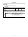
2-2-1 Installation environment conditions
Common installation environment conditions for servo, spindle and power supply unit are shown below.
Ambient
temperature
Environment
Operation: 0 to 55°C (with no freezing), Storage / Transportation: -15°C to 70°C (with no freezing)
Ambient humidity
Atmosphere
Altitude
Vibration/impact
Operation: 90%RH or less (with no dew condensation)
Storage / Transportation: 90%RH or less (with no dew condensation)
Indoors (no direct sunlight)
With no corrosive gas, inflammable gas, oil mist or dust
Operation/Storage: 1000 meters or less above sea level, Transportation: 10000 meters or less above sea level
4.9m/s2 (0.5G) / 49m/s2 (5.0G)
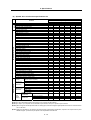
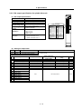
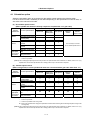
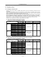
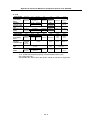
2-2-2 Spindle drive unit
(1) Specifications
Spindle drive unit MDS-C1-SP Series
Spindle drive
unit type
MDS-C1-SPMDS-C1-SPH-
Rated output
Output
[kW]
110
150
3.7
5.5
7.5
11
185
220
260
300
15
18.5
22
26
63
79
97
130
95
115
144
155AC
18
26
37
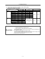
Rated voltage [V]
Rated current [A]
Control
power
75
Rated voltage [V]
Rated current [A]
Input
55
49
270 to 311DC
20
30
41
58
76
Voltage
[V]
200/200 to 230AC
Frequency
[Hz]
50/60
Current
[A]
Max. 0.2
Rush current [A]
Rush
conductivity [ms]
time
Earth leakage current
MAX. 35
MAX. 6
6 (MAX. 15)
[mA]
Control method
Sine wave PWM control method, current control method
Braking
Regenerative braking
Analog voltage ±10V (or +10V) MAX (input impedance approx.10kΩ),
Speed command input
or digital (option) (12 bit binary, signed binary, BCD code 2 digits, BCD code 3 digits)
External analog output
0 to +10V, 2ch (speed meter output, load meter output, data for various adjustments)
Structure
Protection type (Protection method: IP20 [over all] / IP00 [Terminal block TE1])
Cooling method
Weight
Heat radiated
at rated output
Forced wind cooling (fin)
[kg]
[W]
4.4
108
137
5.7
181
Noise
235
6.5
342
Less than 55dB
2 - 12
366
6.3
483
620
2. Specifications
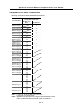
(2) Spindle drive unit function specifications list
MDS-C1-SPA(H)-55~300*
*: Option symbol
R
D
T
RD
RT
○
○
○
○
○
○
○
○
○
○
○
○
○
○
○
○
○
○
○
○
○
○
○
○
○
○
○
○
○
○
○
○
○
○
○
○
○
○
○
○
○
○
○
○
○
○
○
○
○
○
○
○
○
○
○
○
○
○
○
○
○
○
○
○
○
○
○
○
○
○
○
○
○
○
○
○
○
○
○
○
○
○
○
○
○
○
○
○
○
○
○
○
○
○
○
○
○
○
○
○
○
○
○
○
○
○
○
○
○
○
○
○
○
○
○
○
○
○
○
○
○
○
○
○
○
○
○
○
○
○
○
○
○
○
○
○
○
○
○
○
○
○
○
○
○
○
○
○
○
○
○
○
○
○
○
○
○
○
○
○
○
○
○
○
○
○
○
○
○
○
○
○
○
○
○
○
○
○
○
○
○
○
○
○
○
○
○
○
○
○
○
○
○
○
○
○
○
○
○
○
○
○
○
○
○
○
○
○
○
○
○
○
-
○
○
○
○
-
○
○
○
○
○
○
-
○
○
○
○
○
○
○
○
○
○
○
○
-
-
-
-
-
-
○
-
-
-
○
-
○
○
○
Function
Optional function
Miscellaneous function
Basic
function
None
S analog command voltage input±10V
S analog command voltage input 0 to +10V
Machine ready complete input
Forward run/reverse run command input
Override analog input
Torque limit 1 to 3 input
Gear selection1, 2 input
Alarm reset input
Emergency stop input
Speed selection 1 to 3 input
Override valid/invalid input
L coil selection input
Index forward run/reverse run input
Digital speed command input
S-analog high-speed tapping input
Sub-motor selection input
Speed meter output
Load meter output
Controller emergency output signal (contact output)
Pulse feedback output signal
Zero speed output signal
Up-to-speed output signal
Speed detection output signal
Torque reach output signal
In torque limit output signal
In motor forward run/reverse run output signal
In alarm output signal
In emergency stop output signal
In ready ON output signal
Current detect output signal
In coil changeover output signal
In L coil selected output signal
Alarm code output 1 to 4 signal
Orientation complete output signal
Positioning complete output signal
In 1-drive unit 2-motor changeover output signal
In sub-motor selection output signal
1-drive unit
Spindle motor + spindle motor
2-motor
(FR-TK unit is required.)
changeover
Spindle motor + general-purpose motor
Magnetic sensor orientation (1 point)
Orientation
Encoder orientation (multipoint • index)
Motor PLG orientation (multipoint • index )
12 bit binary
Digital speed
Signed binary
command
BCD3 digits
BCD2 digits
1024p/rev encoder
Only for encoder orientation
S-analog specification
high1) Motor PLG orientation
speed
Motor PLG
2) Magnetic sensor orientation
tapping
specification
3) Orientation not available
(Note 1) ○: available
-: not available
(Note 2) For input excluding a basic function input, up to 12 points can be selected.
(Note 3) For output, up to 8 points can be selected for open emitter, and up to 6 points for open collector.
(Note 4) When using the override input terminal in S analog input, and when using the digital speed command, the override function
can not be used.
(Note 5) When the orientation is not applied in the S-analog high-speed tapping specification, Z phase is not output from the pulse
feedback signal. A position loop of spindle must be operated in the NC side.
2 - 13
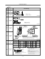
2. Specifications
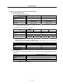
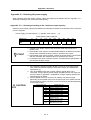
(3) Details on spindle drive unit function specifications
(a) Speed command input
1) Analog speed command input
Input voltage
Tolerable maximum input
voltage
Input part connector, pin No.
Resolution
When using bipolar input
-10 to +10V
When using unipolar input
0 to +10V
-15 to +15V
-15 to +15V
Between CN8A-No.7 pin (SE1) and
No.8 pin (SE2)
10V/ approx. 1940 divisions
(approx. 5.1mV)
Between CN8A-No.17 pin (OR2) and
No.18 pin (OR1)
10V/ approx. 3570 divisions
(approx. 2.8mV)
(Note 1) Tolerable maximum input does not guarantee the speed linearity, but specifies the maximum voltage in which
the drive unit will not be damaged.
2)
Digital speed command input (option)
Binary
(12bit binary)
Signed binary
Contact input Sink • source input available
Input
Tolerable maximum input
voltage
Input part connector
Resolution
3)
BCD code 3digits BCD code 2digits
26.4V
Motor maximum
speed/4095
CN12
Motor maximum
Motor maximum
speed/2048
speed/999
Motor maximum
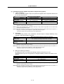
speed/99
Speed selection input
With this function, 8 patterns of speed commands are selected using up to 3 bits in
combination. Speed can be set with a parameter.
Input
Tolerable maximum input
voltage
Input part connector
Minimum setting unit
Speed selection
Contact input Sink and source input available
26.4V
Select maximum three of CN10 general-purpose input
1r/min
(b) Override input
This function is valid when the override input contact set with the general-purpose input is
turned ON.
Input voltage
Tolerable maximum input
voltage
Input part connector, pin No.
Resolution
When using unipolar input
0 to +10V
-15 to +15V
Between CN8A-No.17 pin (OR2) and No.18 pin (OR1)
10V/ approx. 3570 divisions (approx. 2.8mV)
(Note 1) When using unipolar analog input, digital speed command input and speed selection for the speed command,
the override function cannot be used.
2 - 14
2. Specifications
(c) Orientation function (spindle set position stop function) (option)
1) 1 point orientation
When the orientation signal is input, the spindle is stopped at the set position determined
by an internal parameter.
When using external 1024p/rev
encoder or motor PLG
Available stop position
setting range
Stop position resolution
Repeated stop position
accuracy
When using magnetic sensor
360°/4096 divisions
±5°
based on center of magnet and sensor
Approx. 5°/512 divisions
±0.1°
±0.1°
360°
(Note 1) The repeated stop accuracy or resolution in the above table may not satisfy the accuracy according to
backlash or friction torque, etc of machine.
(Note 2) When using magnetic sensor, the position accuracy or stop position range differs from the above table
according to the installation radius.
(Note 3) Motor PLG orientation is possible only when the spindle and motor are coupled, when they are coupled at 1:1
with gears, or when they are coupled at 1:1 (pulley ratio) with a timing belt.
The Z phase signal must be provided to the motor speed detector.
2)
Orientation
The spindle stop position in the orientation command input is changed arbitrarily using
external 12 bits stop position command.
When using external 1024p/rev encoder or motor PLG
Available stop position
setting range
Stop position resolution
Repeated stop position
accuracy
360°(arbitrary according to external stop command)
360°/4096 divisions
±0.1°
(Note 1) The repeated stop accuracy or resolution in the above table may not satisfy the accuracy according to
backlash or friction torque, etc of machine.
(Note 2) Motor PLG orientation is possible only when the spindle and motor are coupled, when they are coupled at 1:1
with gears, or when they are coupled at 1:1 (pulley ratio) with a timing belt.
The Z phase signal must be provided to the motor speed detector.
3)
Multi-point indexing orientation
By setting the orient command and indexing forward run/reverse run to the
general-purpose input, the stop position is changed arbitrarily without one rotation of the
spindle.
When using external 1024p/rev encoder or motor PLG
Available stop position
setting range
Stop position resolution
Repeated stop position
accuracy
360°(arbitrary according to external stop command)
360°/4096 divisions
±0.1°
(Note 1) The repeated stop accuracy or resolution in the above table may not satisfy the accuracy according to
backlash or friction torque, etc of machine.
(Note 2) Motor PLG orientation is possible only when the spindle and motor are coupled, when they are coupled at 1:1
with gears, or when they are coupled at 1:1 (pulley ratio) with a timing belt.
The Z phase signal must be provided to the motor speed detector.
2 - 15
2. Specifications
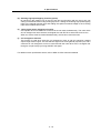
(d) S-analog high-speed tapping function (option)
By structuring the position loop in the NC side and synchronizing with the servo axis, tap
cutting is carried out without using floating tap chuck. Setting the S-analog high-speed tapping
input to the general-purpose input and adding the speed command voltage to the S-analog
input section realize this function.
(e) 1-drive unit 2-motor changeover function
One spindle drive unit rotates two motors that are not used simultaneously. The motor drive
wire is changed over with contactor, and signal wire with FR-TK to select which one to use.
When two motors must be rotated simultaneously, this function cannot be used.
(f) Coil changeover function
This function is used when using the coil changeover motor to gain an extensive constant
output range without a gear. The coil selection signal is set to the general-purpose input, and a
contactor for coil changeover, which is connected with the motor drive wire, is changed over
through a compact relay by turning ON/OFF this signal.
For details on each specification above, refer to MDS-C1-SPA Instruction Manual.
2 - 16
2. Specifications
2-2-3 Power supply unit
Power supply unit MDS-C1-CV Series
Power supply
unit type
MDS-C1-CV-
Rated output
[kW]
37
55
75
110
3.7
5.5
7.5
11.0
Rated voltage [V]
Input
Frequency
Output
Rated current [A]
[V]
220
260
300
370
15.0
18.5
22.0
26.0
30.0
37.0
81
95
107
121
95
115
144
164
50/60 Frequency fluctuation within ±3%
16
20
26
35
49
Rated voltage [V]
Voltage
185
200/200 to 230AC
[Hz]
Rated current [A]
150
66
270 to 311DC
17
20
30
41
58
76
200/200 to 230AC
Frequency
[Hz]
50/60
Control
Current
[A]
Max.0.2
power
Rush current [A]
Rush
conductivity [ms]
time
MAX.35
MAX.6
Converter with power regeneration circuit
Main circuit method
Protection type (Protection method: IP20 [over all] / IP00 [Terminal block TE1])
Structure
Selfcooling
Cooling method
Weight
Heat radiated
at rated output
[kg]
[W]
Forced wind cooling
(internal)
3.4
55
65
80
Forced wind cooling (fin)
4.6
5.8
6.0
8.3
8.4
8.6
8.8
125
155
195
210
260
320
400
Noise
Less than 55dB
2 - 17
2. Specifications
2-2-4 AC reactor
An AC reactor must be installed for each power supply unit.
(1) Specifications
AC reactor type
B-AL-
Compatible
power
MDS-C1-CVsupply unit
type
Rated capacity
[kW]
(30-minute rating)
Rated voltage
[V]
Rated current
[A]
Frequency
[Hz]
Ambient
temperature
7.5K
11K
AC reactor
18.5K
30K
37K
37,55,75
110
150,185
220,260,300
370
7.5
11
18.5
30
37
27
Ambient humidity
Environment
Atmosphere
Altitude
Weight
Vibration/impact
[kg]
3.6
200/200 to 230AC
33
66
110
50/60 Frequency fluctuation within ±3%
Operation: -10 to 60°C (with no freezing),
Storage/Transportation: -10°C to 60°C (with no freezing)
Operation: 80%RH or less (with no dew condensation),
Storage/Transportation: 80%RH or less (with no dew condensation)
Indoors (no direct sunlight)
With no corrosive gas, inflammable gas, oil mist or dust
Operation/Storage: 1000 meters or less above sea level,
Transportation: 10000 meters or less above sea level
9.8m/s2 (1G) / 98m/s2 (10G)
3.0
5.2
6.0
2 - 18
129
10
2. Specifications
2-2-5 D/A output specifications for spindle drive unit
(1) D/A output specifications
Item
Explanation
No. of channels
Output cycle
Output precision
Output voltage range
Output magnification
setting
2ch
444µs (min. value)
8bit
0V to +5V (zero) to +10V,
0V to +10V for meter output
CN9 connector
Pin
1
2
3
4
5
6
7
8
9
10
±1/256 to ±128-fold
CN9 connector
MO1 = Pin 9
MO2 = Pin 19
GND = Pin 1
Phase current feedback output function
U phase current FB : Pin 7
V phase current FB : Pin 17
Output pin
Function
Name
LG
UIFB
MO1
Pin
11
12
13
14
15
16
17
18
19
20
Name
VIFB
MO2
MDS-C1-SPA
(2) Setting the output data
No.
Abbrev.
Parameter name
SP253
DA1NO
D/A output channel 1 data No.
Input the No. of the data to be output to each D/A output channel.
SP254
DA2NO
D/A output channel 2 data No.
1deg=(64000÷65536)
Original data unit
Output magnification
standard setting value
(SP255, SP256)
Output unit for standard
setting
ch1: Speedometer output
10V=max. speed (Zero=0V)
0
Depends on maximum speed
3.5ms
ch2: Load meter output
10V=120% load (Zero=0V)
0
30-minute rating 12%/V
3.5ms
No.
0
Explanation
Output data
Output
cycle
1
–
2
Current command
Rated 100%=4096
8
30-minute rating 20%/V
3.5ms
3
Current feedback
Rated 100%=4096
8
30-minute rating 20%/V
3.5ms
4
Speed feedback
r/min
13
500rpm/V
3.5ms
5
–
80
Control input 1
81
Control input 2
82
Control input 3
83
Control input 4
84
Control output 1
85
Control output 2
86
Control output 3
87
Control output 4
HEX
Bit correspondence
2 - 19
3.5ms
2. Specifications
2-2-6 Explanation of each part
(1) Explanation of each spindle drive unit part
<1>
<2>
<3>
<4>
<5>
<6>
<7>
<8>
<9>
<10>
<11>
<12>
<13>
<14>
MDS-C1-SPA
The connector layout differs according to the unit being used. Refer to each unit's outline drawing
for details.
Each part name
Name
---
Unit status indication LED
---
SW1: Axis No. setting switch
PB1,2,3: Parameter setting button
CN10
---
CN11
CN9A
CN4
CN5
CN6
CN12
CN8A
TE2
TE3
TE1
--------------L+, L–
L11, L21
U, V, W
<14>
Main circuit
<4>
<5>
<6>
<7>
<8>
<9>
<10>
<11>
<12>
<13>
Control circuit
<2>
<3>
Description
LED
SW1,
PB1,
PB2,
PB3
<1>
PE
General-purpose input output / DC power supply connection
connector
Orient position shift / general-purpose output connector
Personal computer connection / analog output connector
Power supply communication connector
Internal PLG encoder connection connector
Magnetic sensor / external encoder connection connector
Digital speed command / general-purpose output connector
Analog speed command / override / pulse output connector
Converter voltage input terminal (DC input)
Control power input terminal (single-phase AC input)
Motor power output terminal (3-phase AC output)
Grounding terminal
(Note1) For customer switching from MDS-A/B Series
Make sure that PE terminal position has changed from UVW terminal to the bottom of the cooling fan.
Screw size
Type
Unit width (mm)
<11> L+, L–
<12> L11,L21
<13> U, V, W
<14>
04 to 37
60
M4 x 12
M4 x 8
Spindle drive unit MDS-C1-SPA55 to 110,150S
150 to 185
90
120
M6 x 14
M4 x 10
M5 x 12
M5 x 12
2 - 20
220 to 300
150
M8 x 14
M8 x 14
2. Specifications
(2) Explanation of each power supply unit part
<2>
<1>
<3>
<4>
<5>
<7>
<6>
<8>
<9>
<10>
<11>
MDS-C1-CV
Bottom view
The connector layout differs according to the unit being used. Refer to each unit's outline drawing
for details.
Each part name
Main circuit
<11>
Control circuit
Name
<1>
<2>
<3>
<4>
<5>
<6>
<7>
<8>
<9>
<10>
LED
SW1
CN4
CN9
--CN23
TE2
TE3
TE1
Description
--------CHARGE LAMP
--L+, L–
L11, L21
MC1
L1, L2, L3
Power supply status indication LED
Power supply setting switch
Spindle communication connector (master)
Spindle communication connector (slave)
TE2 output charging/discharging circuit indication LED
External emergency stop input connector
Converter voltage output terminal (DC output)
Control power input terminal (single-phase AC input)
External contactor control terminal
Power input terminal (3-phase AC input)
Grounding terminal
PE
(Note1) CN23 is located at the bottom of the power supply unit.
(Note2) For customer switching from MDS-A/B Series
Make sure that PE terminal position has changed from UVW terminal to the bottom of the cooling fan.
Screw size
Type
Unit width (mm)
<7> L+, L–
<8> L11, L21
<9> MC1
<10> L1, L2, L3
<11>
37 to 75
60
M4 x 10
M4 x 8
Power supply unit MDS-C1-CV110
150 to 185
90
120
M6 x 16
M4 x 10
M4 x 10
M5 x 12
M5 x 8
2 - 21
220 to 370
150
M8 x 14
M8 x 14
2. Specifications
2-3 Restrictions and precautions
There are restrictions on the layout of spindle drive unit and power supply unit, and on sequence as
follows.
When designing a power distribution box or creating sequence, always consider this section, and satisfy
the following items.
2-3-1 Layout of unit
Arrange the spindle drive unit and power supply unit as follows.
(1) When installing one spindle drive
Spindle
drive
Power
supply
Link bar
(Front)
(2) When installing two spindle drives
1) When the total spindle drive output is 37kW or less
Spindle
drive
Power
supply
Spindle
drive
Link bar
(Front)
2) When the total spindle drive output exceeds 37kW
Spindle
drive
(1)
Power
supply
(1)
Spindle
drive
(2)
Power
supply
(2)
(Front)
Link bar
(Note 1) Install each unit next to each other (vertical direction is not acceptable) with a 3cm or less
clearance between spindle drive unit and power supply unit.
Note that this does not apply to the section between spindle drive (2) and power supply unit (1)
shown in 2) of section (2).
(Note 2) When using section (2) 2), install an ACL (B-AL) on each power supply unit.
2 - 22
2. Specifications
2-3-2 Precautions for installing multiple power supply units
The methods for installing the two spindles are explained here as an example for installing multiple
power supply units.
NC(PC)
MDS-C1-SPA (No.1)
C
N
10
11
12
8A
9A
MDS-C1-CV (No.1)
C
N
4
MDS-C1-SPA (No.2)
C
N
10
11
12
8A
9A
C
N
4
C
N
4
MDS-C1-CV (No.2)
C
N
4
MC1
MC1
L+, LL11, L21
L+, LL11, L21
L1, L2, L3
L1, L2, L3
MC
MC
200VAC
NFB1(No.1)
AC rector
(B-AL No.1)
Contactor (No.1)
NFB1 (No.2)
AC reactor Contactor (No.2)
(B-AL No.2)
(1) Connecting the L+, L-, L11 and L21 link bars
Connect the L+ and L- link bars independently with C1-CV(No.1) and C1-CV(No.2) as shown above.
Make sure that both C1-CV link bars are not short-circuited when connected.
(2) Connecting and selecting NFB1, contactor and AC reactor
An NFB1, a contactor and an AC reactor must be installed independently to each power supply as
shown above. (These cannot be shared.) Note that the contactor, excluding C1-CV-370, can be
omitted.
(3) Connecting the MC1 terminal (A/B-CV)
When using the contactor, set the C1-CV rotary switch to "0", and when not using, set to "1".
2 - 23
2. Specifications
2-3-3 Precautions when installing multiple spindle drive units to one power supply unit
The methods for installing two spindle drive units to one power supply unit are explained here as an
example.
NC(PC)
MDS-C1-SPA (No.1)
C
N
10
11
12
8A
9A
MDS-C1-CV
C
N
4
MDS-C1-SPA (No.2)
C
N
10
11
12
8A
9A
C
N
4
C
N
4
C
N
9
MC1
L+, LL11, L21
L1, L2, L3
MC
200VAC
NFB1
AC reactor
(B-AL)
Contactor
(1) Connecting C1-CV and C1-SPA
Connect C1-CV CN4 and C1-SPA (No. 1) CN4 to C1-CV CN9 and C1-SPA (No.2) CN4. If C1-SPA is
connected with three or more axes, leave CN4 for C1-SPA (No. 3) and following open.
Note that the C1-CV can be controlled (READY ON/OFF, alarm display, etc.) only by the spindle
drive unit connected to C1-CV CN4.
(2) Make sure that the machine ready complete input turns ON and OFF simultaneously for all the
spindle drive units. Do not allow the signal to turn ON and OFF for only one spindle drive unit.
(3) When turning the machine ready complete input OFF during an emergency stop, always have all the
spindle drive units output the zero speed signal before turning the signal OFF.
(4) If an alarm occurs in one of the spindle drive units, turn OFF the machine ready complete input OFF
for all the spindle drive units.
(5) When connecting three or more spindle drive units, install the large-capacity spindle drive units on
both sides of the power supply unit.
2 - 24
3. Characteristics
3-1 Spindle motor ..................................................................................................................................... 3-2
3-1-1 Environmental conditions ............................................................................................................ 3-2
3-1-2 Shaft characteristics .................................................................................................................... 3-2
3-2 Drive unit characteristics .................................................................................................................... 3-3
3-2-1 Environmental conditions ............................................................................................................ 3-3
3-2-2 Heating value .............................................................................................................................. 3-4
3-1
3. Characteristics
3-1 Spindle motor
3-1-1 Environmental conditions
Environment
Conditions
Ambient temperature
Ambient humidity
Storage temperature
Storage humidity
0°C to +40°C (with no freezing)
90%RH or less (with no dew condensation)
–20°C to +65°C (with no freezing)
90%RH or less (with no dew condensation)
Indoors (no direct sunlight);
no corrosive gases, inflammable gases, oil mist or dust
Operation/storage: 1000m or less above sea level
Transportation: 10000m or less above sea level
Atmosphere
Altitude
3-1-2 Shaft characteristics
There is a limit to the load that can be applied on the motor shaft. Make sure that the load applied on the
radial direction, when mounted on the machine, is below the tolerable values given below. These loads
may affect the motor output torque, so consider them when designing the machine.
Spindle motor
Tolerable radial load
SJ-V3.7-02ZM
SJ-V2.2-01, SJ-V3.7-01
SJ-V7.5-03ZM, SJ-V11-06ZM
SJ-V5.5-01, SJ-V11-08ZM
SJ-PMF01830-00
SJ-V7.5-01, SJ-V11-01
SJ-V22-06ZM, SJ-V30-02ZM, SJ-PMF03530-00
SJ-V11-09, SJ-V15-01, SJ-V15-03, SJ-V18.5-01, SJ-V18.5-03
SJ-V22-01, SJ-V22-05, SJ-V26-01, SJ-30A
SJ-22XW5
SJ-37BP
SJ-22XW8, SJ-45BP
SJ-V55-01
490 N
980 N
1470 N
1960 N
2940 N
3920 N
4900 N
5880 N
Radial load
The load point is at the one-half of the shaft length.
3-2
3. Characteristics
3-2 Drive unit characteristics
3-2-1 Environmental conditions
Environment
Ambient temperature
Ambient humidity
Storage temperature
Storage humidity
Atmosphere
Altitude
Vibration
Conditions
0°C to +55°C (with no freezing)
90%RH or less (with no dew condensation)
–15°C to +70°C (with no freezing)
90%RH or less (with no dew condensation)
Indoors (no direct sunlight);
no corrosive gases, inflammable gases, oil mist or dust
Operation/storage: 1000m or less above sea level
Transportation: 10000m or less above sea level
2
Operation/storage: 4.9m/s (0.5G) or less
2
Transportation: 49m/s (5G) or less
(Note) When installing the machine at 1,000m or more above sea level, the heat dissipation
characteristics will drop as the altitude increases. The upper limit of the ambient
temperature drops 1°C with every 100m increase in altitude. (The ambient temperature at
an altitude of 2,000m is between 0 and 45°C.)
3-3
3. Characteristics
3-2-2 Heating value
Each heating value is calculated with the following values.
The values for the spindle drive unit apply for the continuous rated output. The values for the power
supply unit include the AC reactor's heating value.
Servo drive unit
Heating
Type
value [W]
MDS-C1Inside Outside
SPA- 55
SPA- 75
SPA-110
SPA-150S
SPA-150
SPA-185
SPA-220
SPA-260
SPA-300
panel
panel
31
35
41
48
48
62
65
80
98
76
102
140
140
187
280
301
403
522
Power supply unit
Heating
Type
value [W]
MDS-C1Inside Outside
CV- 37
CV- 55
CV- 75
CV-110
CV-150
CV-185
CV-220
CV-260
CV-300
CV-370
panel
panel
21
23
25
26
29
33
35
40
46
54
34
42
55
99
126
162
175
220
274
346
(Note 1) The values for the spindle drive unit are the heating value at the continuous rated output.
(Note 2) The total heating value for the power supply includes the heating value for the AC reactor.
(Note 3) The total heating value for the unit is the total sum of the heating values for the above
corresponding units which are mounted in the actual machine.
Example) When the CV-185, SP-185 units are mounted
Unit total heating value (W) =195+242=437(W)
3-4
4. Dedicated Options
4-1 Orientation option ............................................................................................................................... 4-2
4-1-1 Magnetic sensor .......................................................................................................................... 4-3
4-1-2 Spindle side detector (OSE-1024-3-15-68, OSE-1024-3-15-68-8)............................................. 4-6
4-2 Cables and connectors ...................................................................................................................... 4-8
4-2-1 Cable connection diagram .......................................................................................................... 4-8
4-2-2 List of cables and connectors...................................................................................................... 4-9
4-1
4. Dedicated Options
4-1 Orientation option
Select the orientation option to be required for the spindle control based on the following table.
For each control function, availability of use differs depending on the specifications in the NC side, so
also refer to the manuals of NC side.
(a) No-variable speed control
(When spindle and motor are directly coupled or coupled with a 1:1 gear ratio)
Without orientation option
Spindle
control item
Speed
control
Orientation
control
S-analog
high-speed
synchronous
tap control
Control specifications
Normal cutting control
Constant surface speed
control (lathe)
Thread cutting (lathe)
1-point orientation
control
Multi-point orientation
control
Orientation indexing
Standard synchronous
tap
Synchronous tap after
zero point return
With orientation option
Motor PLG
with Z-phase
Motor PLG
Motor PLG
with Z-phase
{
{
{
{
{
{
×
{
{
×
×
{
×
×
{
×
×
{
{
{
{
×
{
{
Magnetic
sensor
Spindle side
detector
(1020p/rev encoder)
This normally is not used
for no-variable speed control.
(Note 1) { : Control possible
× : Control not possible
(Note 2) The S-analog high-speed synchronous tap control is an option deferent from orientation. For details, refer to “2-2-2 (2)
Spindle drive unit function specifications list”. Setting position loop in the NC side is required.
(b) Variable speed control
(When using V-belt, or when spindle and motor are connected with a gear ratio other than 1:1)
Without orientation option
Spindle
control item
Speed
control
Orientation
control
S-analog
high-speed
synchronous
tap control
Control specifications
Normal cutting control
Constant surface speed
control (lathe)
Thread cutting (lathe)
1-point orientation
control
Multi-point orientation
control
Orientation indexing
Standard synchronous
tap
Synchronous tap after
zero point return
Motor PLG
Motor PLG
with Z-phase
With orientation option
Motor PLG
with Z-phase
Magnetic
sensor
Spindle side
detector
(1020p/rev encoder)
{
{
{
{
{
U
U
U
U
{
×
×
×
×
{
×
×
×
{
{
×
×
×
×
{
×
×
×
×
{
S
S
S
S
{
×
×
×
S
{
(Note 1) { : Control possible
× : Control not possible
U : Control not possible when using V-belt
S : Control not possible when varying the speed with a method other than the gears and timing belt (when using V-belt
or timing belt).
(Note 2) The S-analog high-speed synchronous tap control is an option deferent from orientation. For details, refer to “2-2-2 (2)
Spindle drive unit function specifications list”. Setting position loop in the NC side is required.
4-2
4. Dedicated Options
4-1-1 Magnetic sensor
Prepare the magnetic sensor parts with the following types. When purchasing independently, always
prepare with the required configuration part types.
(1) Type
Type
Independent type
Tolerable
speed [r/min] Drive unit Sensor Magnet
Type
Standard
MAGSENSOR BKO-C1810H01-3
High-speed standard MAGSENSOR BKO-C1730H01.2.6
High-speed small
MAGSENSOR BKO-C1730H01.2.9
MAGSENSOR BKO-C1730H01.2.41
MAGSENSOR BKO-C1730H01.2.42
High-speed ring
MAGSENSOR BKO-C1730H01.2.43
MAGSENSOR BKO-C1730H01.2.44
(Note)
0 to 6000
0 to 12000
0 to 12000
0 to 25000
0 to 25000
0 to 30000
0 to 30000
H01
H01
H01
H01
H01
H01
H01
H02
H02
H02
H02
H02
H02
H02
H03
H06
H09
H41
H42
H43
H44
When preparing with independent types, replace the section following the H in the
prepared type with the independent type.
Example: When preparing only the standard magnetic sensor's sensor section, the
type will be MAGSENSOR BKO-C1810H02.
(2) Outline dimension drawing:
z Drive
unit H01
2-ø5.5 hole
Connector (sensor side)
For BKO-C1810H01, R04-R08F is used.
For BKO-C1730H01, TRC116-21A10-7F is used.
25
Connector (controller cable side)
Unit side (TRC116-21A10-7M)
Cable side (TRC116-12A100-7F10.5)
[Unit: mm]
H02
5.5
25
+100
Cable length 500 -0
ø6
5
25
30
18
20
32
14
1
17.5
Reference
notch
5
z Sensor
Connector
For BKO-C1810H02, R04-R-8M is used.
For BKO-C1730H02, TRC116-12A10-7M is used.
[Unit: mm]
CAUTION
When using the magnetic sensor, orientation control cannot be carried out with a
machine having a gear ratio between the spindle motor and spindle exceeding
1:31.
4-3
4. Dedicated Options
z Magnet
Tolerable
speed
H03
0 to 6000
r/min
H06
0 to 12000
r/min
Outline drawings
Reference hole
38
28
Part
No.
2.5
40
4-ø4.3 hole
50
10
[Unit: mm]
N
S
2-ø4.3 hole
50
0 to 12000
r/min
40
30
Weight: 14.8 ± 0.7g
Installation screw: M4
1.6
7
H09
N.P
[Unit: mm]
D
Case
Cover
0 to 25000
r/min
Stainless case
SUS-303
45°
N
Gap 1±0.1
H42
4-F screw
øC
E
Spun ring
RINGFEDER
RFN8006 J×K
øB
0 to 25000
r/min
øA
H41
Weight: 40 ± 1.5g
Installation screw: M4
7.5
S
2-øG±0.15øH
on circumference
Stop position scale
Sensor head
∗ Polarity (N,S) is indicated on the side wall of cover.
Detection head should be installed so that the reference
notch of sensor head comes on the case side.
Reference
notch
[Unit: mm]
Magnet
Dimensions
H43
0 to 30000
r/min
Model
A
BKO-C1730H41
105
BKO-C1730H42
94
BKO-C1730H43
78
BKO-C1730H44
66
B
70H7+0.030
–0
60H7+0.030
–0
50H7+0.025
–0
40H7+0.025
–0
G
H
J×X
L
Weight
(g)
19 M6×1.0
5
90
70×79
1
1024±4
25
17 M5×0.8
5
79
60×68
1
768±4
66
23
15 M5×0.8
5
66
50×57
1
478±4
54
20
13 M4×0.7
5
54
40×45
1
322±4
C
D
E
90
28
79
F
Cautions on installation of H41 to H44
Reference notch
H44
0 to 30000
r/min
Spindle
Case
G hole
Cover
h6
Gap
Spindle damping screw
Installation of magnet
4-4
1. Tolerance to shaft dimension should be "h6" on the
part for installing a magnet.
2. 2-øG hole can be used for positioning of spindle and
magnet.
3. Magnet shall be installed as shown to the left.
4. Misalignment between sensor head and magnetic
center line shall be within ±2mm.
5. There is an NS indication on the side of the cover.
Install so that the reference notch on the sensor
head comes to the case side.
4. Dedicated Options
(3) Caution on installation of magnet
Observe the following cautions when installing the magnet to the spindle.
(a) Do not place an intense magnetic source near the magnet.
(b) Carefully handle the magnet, avoiding mechanical shock to the magnet.
(c) Secure the magnet to the spindle with M4 screws.
(d) After the magnet is installed, balance the entire spindle.
(e) Align the center of the magnet with the center line of the rotating disk on the spindle. (For the
position relation, refer to the maintenance instruction manual.)
(f) Keep the magnet and its peripheral clean avoiding iron particles and cutting chips from adhering
to the magnet. Failure to observe this could result in malfunction.
(g) Apply lock paint, or other suitable means, to prevent installation screws from becoming loose.
(h) If the magnet is installed on a ground rotating disk, demagnetize the disk because the rotating
disk is thought to be magnetized.
(i) Diameter of rotating disk on which the magnet is installed should be within the range from 80mm
to 120mm. If this range is exceeded, the magnet may be damaged and the orient control may
not be carried out correctly although the speed is below the tolerable speed of the magnet.
(j) If rotation speed of the spindle on which the magnet is installed exceeds 6,000r/min, use a
high-speed type magnet (applicable up to 12,000r/min of rotation speed). If rotation speed
exceeds 12,000r/min, use a ring type magnet.
(k) When installing the magnet on a rotating body plane, keep the speed below 6,000r/min.
(4) Caution on installation of sensor
Observe the following cautions when installing the sensor.
(a) The center line of head should be in line with the center of magnet.
(b) Connector used in preamplifier
BKO-C1810 : Oil proof-type
BKO-C1730 : Not oil proof-type
Install both type at a place not subject to oil.
(c) The cable between the preamplifier and the controller should be laid down apart from
high-voltage cables.
(d) Check the connector wiring, securely engage the receptacle and tighten connector lock screws.
4-5
4. Dedicated Options
4-1-2 Spindle side detector (OSE-1024-3-15-68, OSE-1024-3-15-68-8)
When a spindle and motor are connected with a V-belt, or connected with a gear ratio other than 1:1,
use this spindle side detector (1024p/rev encoder) to detect the position and speed of the spindle. Also
use this detector when orientation control and synchronous tap control, etc are executed under the
above conditions.
(2) Specifications
Detector type
OSE-1024-3-15-68-8
0.1 × 10 kgm or less
0.1 × 10 kgm or less
-4
Mechanical
Inertia
characteristics Shaft friction torque
for rotation
Shaft angle acceleration
Mechanical
configuration
OSE-1024-3-15-68
-4
0.98Nm or less
4
2
0.98Nm or less
2
4
2
10 rad/s or less
10 rad/s or less
Tolerable continuous rotation speed
6000 r/min
8000 r/min
Maximum rotation speed
7030 r/min
8030 r/min
20000h/6000r/min
20000h/8000r/min
0.02mm or less
0.02mm or less
10kg/20kg
Half of value during operation
10kg/20kg
Half of value during operation
1.5kg
1.5kg
Bearing maximum non-lubrication
time
Shaft amplitude
(position 15mm from end)
Tolerable load
(thrust direction/radial direction)
Weight
Working
environment
2
Squareness of flange to shaft
0.05mm or less
Flange matching eccentricity
0.05mm or less
Ambient temperature range
–5°C to +55°C
Storage temperature range
–20°C to +85°C
Humidity
95%Ph
Vibration resistance
5 to 50Hz, total vibration width 1.5mm, each shaft for 30min.
2
Impact resistance
294.20m/s (30G)
(2) Detection signals
Signal name
Number of detection pulses
A, B phase
Z phase
1024p/rev
1p/rev
Connector pin layout
Pin
Function
Pin
Function
A
B
C
D
E
F
G
H
J
A phase
Z phase
B phase
Case earth
+5V
-
K
L
M
N
P
R
S
T
0V
-
A phase
Z phase
B phase
-
4-6
4. Dedicated Options
(3) Outline dimension drawings
68
Ø50
56
33
Ø68
102
MS3102A20-29P
-0.006
1.15
+0.012
0
3
+0.05
0
-0.009
Ø16
5
Ø50 -0.025
Ø14.3
2
Ø15 -0.017
2
0
-0.11
3
4- Ø5.4 hole
+0.14
0
20
Shaft section
Key way magnified figure
Spindle side detector (OSE-1024-3-15-68, OSE-1024-3-15-68-8)
4-7
[Unit: mm]
4. Dedicated Options
4-2 Cables and connectors
4-2-1 Cable connection diagram
The cable connected with CN4, CN5 or CN6 of spindle drive unit in the following diagram can be
ordered from Mitsubishi Electric Corp. as option parts. Cables can only be ordered in the designated
lengths. If a cable connected with the other connector or a cable with special length is required,
purchase a connector or connector set, etc., and create the cable.
Spindle drive unit
(MDS-C1-SPA)
Power supply unit
(MDS-C1-CV)
NC
PC
(1)
DIO
CN4
Meter
Personal
computer
CN5
(1)
CN6
Spindle motor
Spindle side detector/magnetic sensor
(2) Spindle detector cable
<Spindle side detector (1024p/rev encoder)
/magnetic sensor cable>
(2) Spindle detector cable
<Motor PLG / Spindle PLG cable>
4-8
4. Dedicated Options
4-2-2 List of cables and connectors
(1) NC bus cable and connector
(cable and connector between drive unit and power supply unit )
Item
For
CN4
NC bus cable
Model
Contents
SH21
Length:
0.35, 0.5, 0.7,
2, 2.5,
3,
3.5,
4, 4.5,
5,
7,
9,
6,
10,
For
CN4
NC bus cable connector set
1,
1.5,
8,
Drive unit side connector
(3M)
Connector : 10120-6000EL
Shell kit : 10320-3210-000
Drive unit side connector
(3M)
Connector : 10120-6000EL
Shell kit : 10320-3210-000
Drive unit side connector
(3M)
Connector : 10120-3000VE
Shell kit : 10320-52F0-008
Drive unit side connector
(3M)
Connector : 10120-3000VE
Shell kit : 10320-52F0-008
15, 20, 30 m
FCUA-CS000
(Note) The connector manufacturer is subject to change without notice.
4-9
4. Dedicated Options
(2) Spindle detector cable
Item
For CN5
Motor PLG cable
Model
CNP5-
Contents
Spindle drive unit side
connector (3M)
-
Connector type
2: Connector
E: Crimped terminal
Connector : 10120-3000VE
Shell kit : 10320-52F0-008
Spindle motor side connector
For 2-type
(Tyco Electronics AMP)
Plug : 350720-1
Pin : 350689-1
For E-type (J.S.T.)
Crimped terminal: V1.25-4
Axis No. (1 to 8 axis)
1: No. 1 axis
to
8: No. 8 axis
2-type
System No.
None: 1st system
2
: 2nd system
P
: PLC axis
E-type
Length:
2, 5, 10, 20, 30 m
For CN6
Magnetic sensor cable
CNP6M-
-
Connector type
2: Connector
E: Crimped terminal
Spindle drive unit side
connector (3M)
Connector : 10120-3000VE
Shell kit : 10320-52F0-008
Magnetic sensor side
connector
For 2-type (Tajimi Musen)
Plug: TRC116-12A10-7F10.5
For E-type (J.S.T.)
Crimped terminal: V1.25-4
Axis No. (1 to 8 axis)
1: No. 1 axis
to
8: No. 8 axis
2-type
E-type
System No.
None: 1st system
2
: 2nd system
P
: PLC axis
Length:
2, 5, 10, 20, 30 m
Spindle side detector (1024p/rev encoder)
cable
CNP6A -
-
Connector type
2: Straight cannon
3: Angle cannon
E: Crimped terminal
Spindle drive unit side
connector (3M)
Connector : 10120-3000VE
Shell kit : 10320-52F0-008
Spindle side detector
(1024p/rev encoder) side
connector
For 2-type (DDK)
Plug : MS3106A20-29S
Clamp : MS3057-12A
Axis No. (1 to 8 axis)
1: No. 1 axis
to
8: No. 8 axis
For 3-type (DDK)
Plug : MS3108A20-29S
Clamp : MS3057-12A
System No.
None: 1st system
2
: 2nd system
P
: PLC axis
For E-type (J.S.T.)
Crimped terminal: V1.25-4
2-type
3-type
Length:
2, 5, 10, 20, 30 m
(Note) The connector manufacturer is subject to change without notice.
4 - 10
E-type
4. Dedicated Options
(3) External connection cable
Cables shown below are made by the user.
Item
For
CN10,
CN11,
CN12
Model
DIO cable
Contents
Spindle drive unit side
connector (3M)
Connector : 10120-3000VE
Shell kit : 10320-52F0-008
External device
NC device
Programmable controller
External part DIO
Cable: Batch vinyl shield cable
0.2SQ x 20-core (Maximum diameter 12mm or less)
For
CN8A
Analog speed command input
pulse feedback cable
Spindle drive unit side
connector (3M)
External device
NC device
Programmable controller
Connector : 10120-3000VE
Shell kit : 10320-52F0-008
Cable: Twisted pair shield cable
0.3SQ x 4 + 0.3SQ x 3
For
CN9A
For meter output
Spindle drive unit side
connector (3M)
Personal computer
for parameter input • monitor
Connector : 10120-3000VE
Shell kit : 10320-52F0-008
External device
Speed meter
Load meter
Personal computer
Cable: Twisted pair cable
0.3SQ x 2 + 0.3SQ x 2
(Note1) The connector manufacturer is subject to change without notice.
(Note2) Keep the length of the cables, excluding the cable for CN9A, which is connected with a personal computer, to 30m or less.
(The cable connected with a personal computer must be 3m or less.)
(Note3) Do not relay the CNP5, CNP6M or CNP6A cables. Malfunctions may occur due to noise from the motor drive wire or other
cables. (Orientation position could dislocate, vibration could occur, etc.)
If the cable must be relayed, keep the peeled shield section as short as possible (3cm or less), and separate the cable
from the other drive wires and cables. Mitsubishi will not be held liable for any problems that should occur as a result of a
relayed cable. The customer is responsible for providing measures against noise.
4 - 11
5. Peripheral Devices
5-1 Selection of wire ................................................................................................................................. 5-2
5-1-1 Example of wires by unit ............................................................................................................. 5-2
5-2 Selection the AC reactor, contactor and no-fuse breaker.................................................................. 5-4
5-2-1 Standard selection....................................................................................................................... 5-4
5-2-2 Selection of contactor for changing over spindle motor drive wire ............................................. 5-5
5-3 Earth leakage breaker........................................................................................................................ 5-6
5-4 Branch-circuit protection .................................................................................................................... 5-7
5-4-1 Circuit protector ........................................................................................................................... 5-7
5-4-2 Fuse protection............................................................................................................................ 5-7
5-5 Noise filter .......................................................................................................................................... 5-8
5-6 Surge absorber .................................................................................................................................. 5-9
5-7 Speedometer and load meter........................................................................................................... 5-10
5-8 Cable for peripheral control.............................................................................................................. 5-11
5-8-1 Cable for external emergency stop ........................................................................................... 5-11
5-1
5. Peripheral Devices
5-1 Selection of wire
5-1-1 Example of wires by unit
Selected wires must be able to tolerate rated current of the unit’s terminal to which the wire is
connected.
How to calculate tolerable current of an insulated wire or cable is shown in “Tolerable current of electric
cable” (1) of Japanese Cable Makers’ Association Standard (JCS)-168-E (1995), its electric equipment
technical standards or JEAC regulates tolerable current, etc. wire.
When exporting wires, select them according to the related standards of the country or area to export.
In the UL standards, certification conditions are to use wires of 60 oC and 75 oC product. (UL508C)
Wire’s tolerable current is different depending on conditions such as its material, structure, ambient
temperature, etc. Check the tolerable current described in the specification of the wire to use.
Example of wire selections according to each standard is as follows.
(1) 600V vinyl insulated wire (IV wire) 60oC product
(Example according to IEC/EN60204-1, UL508C)
Terminal
name
Unit type
Power supply
unit
Spindle drive
unit
MDS-C1-CV-37
MDS-C1-CV-55
MDS-C1-CV-75
MDS-C1-CV-110
MDS-C1-CV-150
MDS-C1-CV-185
MDS-C1-CV-220
MDS-C1-CV-260
MDS-C1-CV-300
MDS-C1-CV-370
MDS-C1-SPA-55
MDS-C1-SPA-75
MDS-C1-SPA-110
MDS-C1-SPA-150
MDS-C1-SPA-185
MDS-C1-SPA-220
MDS-C1-SPA-260
MDS-C1-SPA-300
TE1
(L1, L2, L3,
2
mm
3.5
3.5
5.5
14
22
30
38
50
60
3.5
5.5
8
14
22
30
38
60
)
AWG
12
12
10
6
4
3
2
12
10
8
6
4
3
2
-
TE2
(L+, L-)
2
mm
AWG
TE3
(L11, L21, L12, L22, MC1)
2
mm
AWG
Same as TE1
1.25 to 2
16 to 14
Match with TE2 of
selected power supply
unit
1.25 to 2
16 to 14
(2) 600V double (heat proof) vinyl insulated wire (HIV wire) 75 oC product
(Example according to IEC/EN60204-1, UL508C)
Terminal
name
Unit type
Power supply
unit
Spindle drive
unit
MDS-C1-CV-37
MDS-C1-CV-55
MDS-C1-CV-75
MDS-C1-CV-110
MDS-C1-CV-150
MDS-C1-CV-185
MDS-C1-CV-220
MDS-C1-CV-260
MDS-C1-CV-300
MDS-C1-CV-370
MDS-C1-SPA-55
MDS-C1-SPA-75
MDS-C1-SPA-110
MDS-C1-SPA-150
MDS-C1-SPA-185
MDS-C1-SPA-220
MDS-C1-SPA-260
MDS-C1-SPA-300
TE1
(L1, L2, L3, )
2
mm
AWG
2
14
3.5
12
5.5
10
14
6
14
6
22
4
30
3
38
2
38
2
50
2
14
3.5
12
5.5
10
14
6
14
6
22
4
30
3
38
2
5-2
TE2
(L+, L-)
2
mm
AWG
TE3
(L11, L21, L12, L22, MC1)
2
mm
AWG
Same as TE1
1.25 to 2
16 to 14
Match with TE2 of
selected power supply
unit
1.25 to 2
16 to 14
5. Peripheral Devices
(3) 600V bridge polyethylene insulated wire (IC) 105oC product
(Example according to JEAC8001)
Terminal
name
Unit type
Power supply
unit
Spindle drive
unit
MDS-C1-CV-37
MDS-C1-CV-55
MDS-C1-CV-75
MDS-C1-CV-110
MDS-C1-CV-150
MDS-C1-CV-185
MDS-C1-CV-220
MDS-C1-CV-260
MDS-C1-CV-300
MDS-C1-CV-370
MDS-C1-SPA-55
MDS-C1-SPA-75
MDS-C1-SPA-110
MDS-C1-SPA-150
MDS-C1-SPA-185
MDS-C1-SPA-220
MDS-C1-SPA-260
MDS-C1-SPA-300
CAUTION
TE1
(L1, L2, L3,
)
2
mm
AWG
2
14
2
14
3.5
12
5.5
10
8
8
14
6
14
6
22
4
38
2
38
2
2
14
3.5
12
5.5
10
14
6
14
6
22
4
30
3
38
2
TE2
(L+, L-)
2
mm
2
3.5
3.5
14
14
22
22
30
38
50
AWG
14
12
12
6
6
4
4
3
2
-
Match with TE2 of
selected power supply
unit
TE3
(L11, L21, L12, L22, MC1)
2
mm
AWG
1.25 to 2
16 to 14
1.25 to 2
16 to 14
1. Selection conditions follow IEC/EN60204-1, UL508C, JEAC8001.
• Ambient temperature is maximum 40°C.
• Cable installed on walls without ducts or conduits.
To use the wire under conditions other than above, check the standards you
are supposed to follow.
2. The maximum wiring length to the motor is 30m.
If the wiring distance between the drive unit and motor is 20m or longer, use a
thick wire so that the cable voltage drop is 2% or less.
3. Always wire the grounding wire.
5-3
5. Peripheral Devices
5-2 Selection the AC reactor, contactor and no-fuse breaker
5-2-1 Standard selection
Install an AC reactor, contactor and no-fuse breaker (NFB) per one power supply unit. Refer to the table
below and select them according to each power supply unit capacity.
Selection of AC reactor, contactor and no-fuse breaker (NFB)
Power supply unit
capacity
3.7 to 7.5kW
11kW
15 to 18.5kW
22 to 30kW
37kW
AC reactor
B-AL-7.5K
B-AL-11K
B-AL-18.5K
B-AL-30K
B-AL-37K
Recommended
contactor
(Special order part)
S-N25 200V
S-N35 200V
S-N50 200V
S-N80 200V
S-N150 200V
Recommended
main circuit NFB
(Special order part)
NF50CS3P-40A0
5
NF50CS3P-50A05 NF100CS3P-100A05 NF225CS3P-150A05 NF225CS3P-175A05
An NFB or CP (circuit protector) can be used as the motor fan breaker.
Select the NFB or CP using a value approximately double the motor fan rated current value shown below.
Contact the NFB or CP manufacturer for details on the recommended wire size, etc.
Recommended
motor fan NFB
(Special order part)
Spindle motor
frame size
71
90
112
132
160
180
Motor fan
rated current
0.1A
0.2A
0.2A
0.2A
0.6A
0.6A
* A rush current that is approximately double the above rated current flows when the motor starts.
(Note 1) In the above table, a special order part refers to a part that cannot be ordered from Mitsubishi,
and which must be prepared by the user.
(Note 2) To comply with the EC Directives, use contactors and NFB that comply with the EN/IEC
Standards.
CAUTION
If a breaker is shared by several power supply units, the breaker may not
activate when a short-circuit fault occurs in a small capacity unit. This is
dangerous, so never share the breakers.
5-4
5. Peripheral Devices
5-2-2 Selection of contactor for changing over spindle motor drive wire
When using coil changeover motor and 1-drive unit 2-motor changeover function, select a contactor for
changing over motor drive wire from the table below according to the capacity of spindle drive unit to be
used.
Spindle drive unit type
MDS-A/B-SPA(H)-04
MDS-A/B-SPA(H)-075
MDS-A/B-SPA(H)-15
MDS-A/B-SPA(H)-22
MDS-A/B-SPA(H)-37
MDS-A/B/C1-SPA(H)-55
MDS-A/B/C1-SPA(H)-75
MDS-A/B/C1-SPA(H)-110
MDS-A/B/C1-SPA(H)-150
MDS-A/B/C1-SPA(H)-185
MDS-A/B/C1-SPA(H)-220
MDS-A/B/C1-SPA(H)-260
MDS-A/B/C1-SPA(H)-300
MDS-B-SPA(H)-370
MDS-B-SPA(H)-450
MDS-B-SPA(H)-550
Recommended contactor type
S-N10
S-N10
S-N10
S-N10
S-N18
S-N20
S-N25
S-N35
S-N50
S-N65
S-N80
S-N80
S-N125
S-N150
S-N180
S-N300
(Note 1) These contactors are prepared by the user.
(Note 2) Use the EN/IEC Standards compliant parts in compliance with EC Directives.
5-5
5. Peripheral Devices
5-3 Earth leakage breaker
When installing an earth leakage breaker, select the breaker on the following basis to prevent the
breaker from malfunctioning by the higher frequency earth leakage current generated in the spindle
drive unit.
(1) Selection
Obtaining the earth leakage current for all drive units referring to the following table, select an earth
leakage breaker within the “rated non-operation sensitivity current”.
Usually use an earth leakage breaker for inverter products that function at a leakage current within
the commercial frequency range (50 to 60Hz).
If a product sensitive to higher frequencies is used, the breaker could malfunction at a level less
than the maximum earth leakage current value.
Earth leakage current for each unit
Unit
Earth leakage current
Maximum earth leakage current
MDS-C1-SPA-55 to 300
6mA
15mA
(Note1) Maximum earth leakage current: Value that considers wiring length and grounding, etc.
(Commercial frequency 50/60Hz)
(Note2) The earth leakage current in the power supply unit side is included in the drive unit side.
(2) Measurement of earth leakage current
When actually measuring the earth leakage current, use a product that is not easily affected by the
higher frequency earth leakage current. The measurement range should be 50 to 60Hz.
POINT
1. The earth leakage current tends to increase as the motor capacity increases.
2. A higher frequency earth leakage current will always be generated because the
inverter circuit in the drive unit switches the transistor at high speed. Always
ground to reduce the higher frequency earth leakage current as much as
possible.
3. An earth leakage current containing higher frequency may reach approx.
several hundreds of mA. According to IEC479-2, this level is not hazardous to
the human body.
5-6
5. Peripheral Devices
5-4 Branch-circuit protection
5-4-1 Circuit protector
This breaker is used to switch the control power and to provide overload and short-circuit protection.
When connecting a circuit protector or breaker to the power input (TE3 terminals L11 and L21) for the
control circuit, use a product that does not trip (incorrectly activate) by a rush current when the power is
turned ON. A circuit protector with inertial delay and an operation delayed type breaker are available to
prevent unnecessary tripping. Select the product to be used according to the machine specifications.
The rush current and rush conductivity time differ according to the power impedance and power ON
timing, so select a product that does not trip even under the conditions listed in the following table.
I [A]
Rush conductivity time:
Time to reach 36.8% of rush current; equivalent to breaker
operation characteristics operation time.
Rush current: Ip=35
36.8%
t [ms]
Time constant: T=6
POINT
When collectively protecting the control circuit power for multiple units, select a
circuit protector or breaker that satisfies the total sum of the rush current Ip.
The largest value is used for the rush conductivity time T.
5-4-2 Fuse protection
The fuse of branch-circuit protection must use UL class CC, J or T. In the selection, please consider
rush current and rush conductive time.
Selection of branch-circuit protection fuse
Fuse (Class CC)
Connected total of unit
Rated [V]
1–4
20
600
AWG
16 to 14
35
5–8
CAUTION
Wire Size
Current [A]
For continued protection against risk of fire, replace only with same type 600
V, 20 or 35 A (UL CLASS CC) fuse.
5-7
5. Peripheral Devices
5-5 Noise filter
(1) Selection
Use an EMC noise filter if the noise conducted to the power line must be reduced. Select an EMC
noise filter taking the power supply unit's input rated voltage and input rated current into
consideration.
(2) Noise filter mounting position
Install the noise filter to the power supply unit’s power input as the diagram below indicates.
Power
distribution panel
Power supply unit
AC reactor Contactor
Breaker
R
Power
supply
Noise filter
S
T
MDS-C1-CV
(Note) The noise filter must be prepared by the user.
Recommended devices: Okaya Electric Industries
Soshin Electric
3SUP-HL-ER-6B Series
HF3000C-TMA Series
Contact: Okaya Electric Industries Co., Ltd. Telephone: 03-3424-8120
(+81-3-3424-8120)
http://www.okayaelec.co.jp
Soshin Electric Co., Ltd.
Telephone: 03-3775-9112
(+81-3-3775-9112)
http://www.soshin.co.jp
(Note) The above devices may be changed at the manufacturer's discretion.
Contact each manufacturer for more information.
5-8
5. Peripheral Devices
5-6 Surge absorber
When controlling a magnetic brake of a servomotor in DC OFF circuit, a surge absorber must be
installed to protect the relay contacts and brakes. Commonly a varistor is used.
(1) Selection of varistor
When a varistor is installed in parallel with the coil, the surge voltage can be adsorbed as heat to
protect a circuit. Commonly a 120V product is applied. When the brake operation time is delayed,
use a 220V product. Always confirm the operation with an actual machine.
(2) Specifications
Select a varistor with the following or equivalent specifications. To prevent short-circuiting, attach a
flame resistant insulation tube, etc., onto the leads as shown in the following outline dimension
drawing.
Varistor specifications
Varistor
voltage
rating
(range)
Varistor type
ERZV10D121
TNR10V121K
ERZV10D221
TNR10V221K
Rating
Tolerable
circuit voltage
Surge current
withstand level
(A)
(V)
AC (V)
DC (V)
1 time
120
(108 to 132)
75
100
3500
2500
220
(198 to 242)
140
180
3500
2500
Energy
withstand level
(J)
2 times 10/1000us
Max. limit
Power voltage
Electrostatic
capacity
(reference
value)
2ms
(W)
(V)
(pF)
20
14.5
0.4
200
1400
39
27.5
0.4
360
410
(Note 1) Selection condition: When ON/OFF frequency is 10 times/min or less, and exciting current is 2A or less
(Note 2) ERZV10D121 and ERZV10D221 are manufactured by Matsushita Electric Industrial Co., Ltd.
TNR10V121K and TNR10V221K are manufactured by MARCON Electronics Co., Ltd.
Contact: Matsushita Electronic Components Co., Ltd : http://www.panasonic.co.jp/ maco/
MARCON Electronics Co., Ltd. Telephone : (Kanto)03-3471-7041 (+81-3-3471-7041)
(Kinki) 06-6364-2381 (+81-3-6364-2381)
(Chubu) 052-581-2595 (+81-52-581-2595)
(3) Outline dimension drawing
• ERZV10D121, ERZV10D221
11.5
20.0
POINT
[Unit: mm]
Insulation tube
Normally use a product with 120V varistor voltage. If there is no allowance for the brake
operation time, use the 220V product. A varistor whose voltage exceeds 220V cannot be
used, as such varistor will exceed the specifications of the relay in the unit.
5-9
5. Peripheral Devices
5-7 Speedometer and load meter
Speedometer and load meter can be output from the D/A output which is for measuring control data.
(1) Speedometer output
MO1out put voltage (V)
When speedometer is output, +10V DC is output at the motor’s maximum speed regardless of the
motor’s rotation direction. The following specifications are recommended for the display.
(a) Type YM-8G type DC voltage type (Mitsubishi)
(b) Rating 10VDC full scale
(c) Internal impedance approx. 10kΩ
10
0
Maximum rotation speed
Motor rotation speed (r/min)
Speedometer output specification
(2) Load meter output
Motor output capacity (kW)
The load meter indicates the percentage of the load in respect to the motor's rated output. The
relation of the motor output capacity [kW] and load meter display [%] is as follows.
Overload (for one minute)
zone
50%ED (15-minute)
(30-minute) zone
Load meter 120%
Load meter 100%
Continuous rating
Load meter
30-minute rating
X 100%
Continuous rating zone
0
1500
6000
8000
Motor rotation speed (r/min)
Load meter output specification
The following specifications are recommended for the display.
(a) Type YM-8G type DC voltage type (Mitsubishi)
(b) Rating 10VDC full scale
(c) Internal impedance approx. 10kΩ
(d) Scale indicating alarm at 100% or above (see right figure)
40
60
20
0
100
%
Load meter display
5 - 10
Red zone
80
120
5. Peripheral Devices
5-8 Cable for peripheral control
5-8-1 Cable for external emergency stop
Prepare the cable below for external emergency stop function (dual emergency stop function). The
cable for external emergency stop must be prepared by the user.
External emergency
stop connector
Bottom view of MDS-C1-CV
No.
Item
Type
101
102
Connector
Contact
2-178288-3
1-175218-2
Manufacturer
Tyco Electronics AMP
Tyco Electronics AMP
Wire size:0.5 to 1.25SQ
101 102
3
+
1
-
CN23
Drive unit side
5 - 11
Appendix 1. Outline Dimension Drawings
Appendix 1-1 Outline dimension drawings of spindle motor ..................................................................A1-2
Appendix 1-1-1 SJ Series ...................................................................................................................A1-2
Appendix 1-1-2 SJ-V Series ...............................................................................................................A1-5
Appendix 1-1-3 SJ-VS Series ...........................................................................................................A1-15
Appendix 1-2 Unit outline dimension drawings ....................................................................................A1-17
Appendix 1-2-1 Spindle drive unit.....................................................................................................A1-17
Appendix 1-2-2 Power supply unit ....................................................................................................A1-21
Appendix 1-2-3 AC rector .................................................................................................................A1-25
A1 - 1
Appendix 1. Outline Dimension Drawings
Appendix 1-1 Outline dimension drawings of spindle motor
Appendix 1-1-1 SJ Series
• SJ-30A with standard flange
850
740
665.5
Terminal box
110
7
20
φ51
310
7
189
60
4-φ19
5
110
90
10.5
A
Exhaust air
φ
30
0
32
8
φ
43
A
5
3 5°
Cooling fan
Cooling air inlet
16
55m6
A
A
Cross section
A-A
[Unit: mm]
(Note 1) Provide a clearance of 30mm or more between the cooling fan and wall.
(Note 2) The shaft can also be mounted upward.
(Note 3) If the suspension bolts are removed during operation, plug the screw holes with bolts.
• SJ-30A with standard legs
Terminal box
850
505
430.5
345
230
110
6
312
189
90 10.5
6
A
Cooling
air inlet
Exhaust air
A
Cooling fan
4-Ø15
127 127
304
108
55
16
A
127 127
310
55m6 A
Cross section
A-A
[Unit: mm]
(Note 1) Provide a clearance of 30mm or more between the cooling fan and wall.
(Note 2) If the suspension bolts are removed during operation, plug the screw holes with bolts.
A1 - 2
Appendix 1. Outline Dimension Drawings
• SJ-37BP, SJ-22XW5 with standard flange
Terminal box
909
769
701.5
140
530
25
7
7
350
φ51
224
68
4-φ19
5
140
110
A
15
Exhaust air
5
37
φ
0
35
φ
A
50
9
35°
Cooling air inlet
Cooling fan
18
A
A
60m6
Cross section
A-A
[Unit: mm]
(Note 1) Provide a clearance of 30mm or more between the cooling fan and wall.
(Note 2) The shaft can also be mounted upward.
(Note 3) If the suspension bolts are removed during operation, plug the screw holes with bolts.
• SJ-37BP, SJ-22XW5 with standard legs
909
Terminal box
400.5
508.5
247.5
140
6
352
224
441
110
6
15
A
Cooling
air inlet
Exhaust air
A
Cooling fan
139.5
139.5
121
338
70
139.5
139.5
350
18
A
60m6 A
Cross section
A-A
[Unit: mm]
(Note 1) Provide a clearance of 30mm or more between the cooling fan and wall.
(Note 2) If the suspension bolts are removed during operation, plug the screw holes with bolts.
A1 - 3
Appendix 1. Outline Dimension Drawings
• SJ-45BP, SJ-22XW8 with standard flange
932
792
733
Terminal box
140
7
30
φ63
378
7
4-φ19
278
5
73
140
110
15
A
1
φ
40
0
42
A
φ
58
Exhaust air
5
35°
Cooling fan
Cooling air inlet
φ425
18
A
A
60m6
Cross section
A-A
[Unit: mm]
(Note 1) Provide a clearance of 30mm or more between the cooling fan and wall.
(Note 2) The shaft can also be mounted upward.
(Note 3) If the suspension bolts are removed during operation, plug the screw holes with bolts.
• SJ-45BP, SJ-22XW8 with standard legs
932
Terminal box
425.5
506.5
272.5
140
6
380
278
447.5
6
φ63
110
15
A
Cooling
air inlet
Exhaust air
A
Cooling fan
152.5
152.5
133
4-φ19
85
385
159
159
400
18
A
60m6 A
Cross section
A-A
[Unit: mm]
(Note 1) Provide a clearance of 30mm or more between the cooling fan and wall.
(Note 2) If the suspension bolts are removed during operation, plug the screw holes with bolts.
A1 - 4
Appendix 1. Outline Dimension Drawings
Appendix 1-1-2 SJ-V Series
• SJ-V2.2-01, SJ-V3.7-02ZM with standard flange
φ35
360
300
265
Terminal box
60
130
12
Flange
5
□174
168
48
45
4-φ12
8
A
φ
A
5
18
90
φ1
Exhaust air
φ
22 0
8
Cooling fan
Cooling air inlet
5
□176
5
2-M6 Screw
16
φ28j6
A
A
Cross section
A-A
[Unit: mm]
(Note 1) Provide a clearance of 30mm or more between the cooling fan and wall.
(Note 2) The shaft can also be mounted upward.
(Note 3) If the suspension bolts are removed during operation, plug the screw holes with bolts.
• SJ-V2.2-01, SJ-V3.7-02ZM with standard legs
φ35
Terminal box
360
300
265
130
60
176
5
45
5
168
8
A
Cooling
air inlet
Exhaust air
A
Cooling fan
75
105
56
41
4-φ10
35
70
70
180
8
2-M6 Screw
16
A
φ28j6
A
Cross section
A-A
[Unit: mm]
(Note 1) Provide a clearance of 30mm or more between the cooling fan and wall.
(Note 2) The shaft can also be mounted upward.
(Note 3) If the suspension bolts are removed during operation, plug the screw holes with bolts.
A1 - 5
Appendix 1. Outline Dimension Drawings
• SJ-V3.7-01 with standard flange
φ35
390
330
295
60
160
Terminal box
12
Flange
5
□174
168
48
45
4-φ12
8
A
Exhaust air
90
φ1
5
18
φ
A
φ2
20
Cooling fan
Cooling air inlet
8
5
□176
5
2-M6 Screw
16
φ28j6
A
A
Cross section
A-A
[Unit: mm]
(Note 1) Provide a clearance of 30mm or more between the cooling fan and wall.
(Note 2) The shaft can also be mounted upward.
(Note 3) If the suspension bolts are removed during operation, plug the screw holes with bolts.
• SJ-V3.7-01 with standard legs
φ35
390
330
295
Terminal box
60
160
5
45
176
5
168
8
A
Cooling
air inlet
Exhaust air
A
Cooling fan
100
130
56
41
4-φ10
35
70
70
180
8
2-M6 Screw
16
φ28j6
A
A
Cross section
A-A
[Unit: mm]
(Note 1) Provide a clearance of 30mm or more between the cooling fan and wall.
(Note 2) The shaft can also be mounted upward.
(Note 3) If the suspension bolts are removed during operation, plug the screw holes with bolts.
A1 - 6
Appendix 1. Outline Dimension Drawings
• SJ-V5.5-01 with standard flange
485
425
390
Terminal box
60
255
Flange
12 φ44
48
□174
168
5
4-φ12
45
7.5
A
φ
A
Cooling fan
18
5
90
φ1
Exhaust air
φ
22
0
Cooling air inlet
5
□176
5
7
φ
22
φ28h6
3-M4 Screw
A
A
Cross section
A-A
[Unit: mm]
(Note 1) Provide a clearance of 30mm or more between the cooling fan and wall.
(Note 2) The shaft can also be mounted upward.
(Note 3) If the suspension bolts are removed during operation, plug the screw holes with bolts.
• SJ-V5.5-01 with standard legs
φ44
Terminal box
485
425
255
390
60
5
45
7.5
176
168
5
A
Cooling
air inlet
Exhaust air
A
Cooling fan
159
190
4-φ10
56
41
35
70
70
180
7
22
φ
φ28h6
A
3-M4 Screw
A
Cross section
A-A
[Unit: mm]
(Note 1) Provide a clearance of 30mm or more between the cooling fan and wall.
(Note 2) The shaft can also be mounted upward.
(Note 3) If the suspension bolts are removed during operation, plug the screw holes with bolts.
A1 - 7
Appendix 1. Outline Dimension Drawings
• SJ-V7.5-01, SJ-V7.5-03ZM, SJ-V11-06ZM with standard flange
φ44
520
440
403
Terminal box
80
Flange
238
□204
198
13
47
5
4-φ15
63
A
φ
A
215
25
φ2
Exhaust air
8
φ2
50
Cooling fan
Cooling air inlet
□208
5
5
10
22
φ
φ32h6
3-M5 Screw
A
A
Cross section
A-A
[Unit: mm]
(Note 1) Provide a clearance of 30mm or more between the cooling fan and wall.
(Note 2) The shaft can also be mounted upward.
(Note 3) If the suspension bolts are removed during operation, plug the screw holes with bolts.
• SJ-V7.5-01, SJ-V7.5-03ZM, SJ-V11-06ZM with standard legs
φ44
Terminal box
520
440
403
80
238
5
63
208
198
5
8
A
Cooling
air inlet
Exhaust air
A
Cooling fan
140
180
4-φ12
70
50
45
95
95
230
10
φ22
φ32h6
3-M5 Screw
A
A
Cross section
A-A
[Unit: mm]
(Note 1) Provide a clearance of 30mm or more between the cooling fan and wall.
(Note 2) The shaft can also be mounted upward.
(Note 3) If the suspension bolts are removed during operation, plug the screw holes with bolts.
A1 - 8
Appendix 1. Outline Dimension Drawings
• SJ-V11-01, SJ-V11-08ZM with standard flange
φ44
600
490
453
Terminal box
110
Flange
288
□204
198
13
65
5
4-φ15
80
A
10
15
25
φ2
A
φ2
Exhaust air
φ2
50
Cooling fan
Cooling air inlet
5
□208
5
14
φ
40
φ48h6
3-M5 Screw
A
A
Cross section
A-A
[Unit: mm]
(Note 1) Provide a clearance of 30mm or more between the cooling fan and wall.
(Note 2) The shaft can also be mounted upward.
(Note 3) If the suspension bolts are removed during operation, plug the screw holes with bolts.
• SJ-V11-01, SJ-V11-08ZM with standard legs
φ44
Terminal box
600
490
453
110
288
5
80
208
198
5
10
A
Cooling
air inlet
Exhaust air
A
Cooling fan
140
180
70
50
4-φ12
14
40
φ
φ48h6
45
95
95
230
3-M5 Screw
A
A
Cross section
A-A
[Unit: mm]
(Note 1) Provide a clearance of 30mm or more between the cooling fan and wall.
(Note 2) The shaft can also be mounted upward.
(Note 3) If the suspension bolts are removed during operation, plug the screw holes with bolts.
A1 - 9
Appendix 1. Outline Dimension Drawings
• SJ-V15-01, SJ-V18.5-01, SJ-V11-09, SJ-V15-03, SJ-V22-06ZM with standard flange
φ44
579.5
469.5
434.5
259.5
Terminal box
110
266
□250 Flange
198
20
65
4-φ15
5
80
10
A
Exhaust air
5
26
75
φ
φ2
A
φ3
00
Cooling fan
Cooling air inlet
14
φ
5
40
φ48h6
A
□262
5
3-M5 Screw
A
Cross section
A-A
[Unit: mm]
(Note 1) Provide a clearance of 30mm or more between the cooling fan and wall.
(Note 2) The shaft can also be mounted upward.
(Note 3) If the suspension bolts are removed during operation, plug the screw holes with bolts.
• SJ-V15-01, SJ-V18.5-01, SJ-V11-09, SJ-V15-03, SJ-V22-06ZM with standard legs
φ44
Terminal box
579.5
469.5
434.5
259.5
110
5
80
262
198
10
5
A
Cooling
air inlet
Exhaust air
A
Cooling fan
178
108
250
60
50
4-φ15
127
127
295
14
φ
40
φ48h6
A
3-M5 Screw
A
Cross section
A-A
[Unit: mm]
(Note 1) Provide a clearance of 30mm or more between the cooling fan and wall.
(Note 2) The shaft can also be mounted upward.
(Note 3) If the suspension bolts are removed during operation, plug the screw holes with bolts.
A1 - 10
Appendix 1. Outline Dimension Drawings
• SJ-V30-02ZM with standard flange
φ51
649.5
539.5
Terminal box
110
499.5
266
329.5
□250 Flange
238
20
65
4-φ15
5
80
A
10
φ
26
5
75
A
φ2
Exhaust air
φ3
00
Cooling fan
Cooling air inlet
5
□262
5
14
φ
40
3-M5 Screw
φ48h6
A
A
Cross section
A-A
[Unit: mm]
(Note 1) Provide a clearance of 30mm or more between the cooling fan and wall.
(Note 2) The shaft can also be mounted upward.
(Note 3) If the suspension bolts are removed during operation, plug the screw holes with bolts.
• SJ-V30-02ZM with standard legs
φ51
Terminal box
649.5
539.5
499.5
110
329.5
262
238
5
80
10
5
A
Cooling
air inlet
Exhaust air
A
Cooling fan
178
108
250
60
50
4-φ15
127
127
295
14
φ
40
3-M5 Screw
φ48h6
A
A
Cross section
A-A
[Unit: mm]
(Note 1) Provide a clearance of 30mm or more between the cooling fan and wall.
(Note 2) The shaft can also be mounted upward.
(Note 3) If the suspension bolts are removed during operation, plug the screw holes with bolts.
A1 - 11
Appendix 1. Outline Dimension Drawings
• SJ-V22-01, SJ-V18.5-03, SJ-V22-05 with standard flange
φ51
649.5
539.5
Terminal box
110
499.5
266
329.5
□250 Flange
238
20
65
4-φ15
5
90
A
10.5
φ
5
26
75
A
φ2
Exhaust air
φ3
00
Cooling fan
Cooling air inlet
5
□262
5
16
φ
45
3-M5 Screw
φ55m6
A
A
Cross section
A-A
[Unit: mm]
(Note 1) Provide a clearance of 30mm or more between the cooling fan and wall.
(Note 2) The shaft can also be mounted upward.
(Note 3) If the suspension bolts are removed during operation, plug the screw holes with bolts.
• SJ-V22-01, SJ-V18.5-03, SJ-V22-05 with standard legs
φ51
Terminal box
649.5
539.5
499.5
110
329.5
262
238
5
90
10.5
5
A
Cooling
air inlet
Exhaust air
A
Cooling fan
178
108
275
60
50
4-φ15
127
127
295
16
φ
45
3-M5 Screw
φ55m6
A
A
Cross section
A-A
[Unit: mm]
(Note 1) Provide a clearance of 30mm or more between the cooling fan and wall.
(Note 2) The shaft can also be mounted upward.
(Note 3) If the suspension bolts are removed during operation, plug the screw holes with bolts.
A1 - 12
Appendix 1. Outline Dimension Drawings
• SJ-V26-01 with standard flange
φ51
695.5
585.5
545.5
Terminal box
110
Flange
□250
238
20
375.5
65
5
90
A
10.5
A
φ
Cooling air inlet
16
φ
5
26
5
75
φ2
Exhaust air
Cooling fan
4-φ15
□262
φ3
00
5
45
3-M5 Screw
φ55m6
A
A
Cross section
A-A
[Unit: mm]
(Note 1) Provide a clearance of 30mm or more between the cooling fan and wall.
(Note 2) The shaft can also be mounted upward.
(Note 3) If the suspension bolts are removed during operation, plug the screw holes with bolts.
• SJ-V26-01 with standard legs
φ51
Terminal box
695.5
585.5
545.5
110
375.5
5
90
262
238
5
10.5
A
Cooling
air inlet
Exhaust air
A
Cooling fan
178
108
275
60
4-φ15
50
127
127
295
16
45
φ
3-M5 Screw
φ55m6
A
A
Cross section
A-A
[Unit: mm]
(Note 1) Provide a clearance of 30mm or more between the cooling fan and wall.
(Note 2) The shaft can also be mounted upward.
(Note 3) If the suspension bolts are removed during operation, plug the screw holes with bolts.
A1 - 13
Appendix 1. Outline Dimension Drawings
• SJ-V55-01 with standard flange
φ63
864
Terminal box
724
140
672
402
30
75
□480
348
5
110
4-φ24
15
A
Exhaust air
10
φ5
00
φ5
A
φ5
50
35°
Cooling fan
2-M10
Cooling air inlet
20
φ
65
φ75m6
3-M6 Screw
A
A
Cross section
A-A
[Unit: mm]
(Note 1) Provide a clearance of 30mm or more between the cooling fan and wall.
(Note 2) The shaft can also be mounted upward.
(Note 3) If the suspension bolts are removed during operation, plug the screw holes with bolts.
• SJ-V55-01 with standard legs
φ63
Terminal box
864
724
140
672
402
6
110
426
348
15
6
A
Cooling
air inlet
Exhaust air
A
Cooling fan
286
366
4-φ19
149
109
80
178
178
435
20
φ
65
3-M6 Screw
φ75m6
A
A
Cross section
A-A
[Unit: mm]
(Note 1) Provide a clearance of 30mm or more between the cooling fan and wall.
(Note 2) The shaft can also be mounted upward.
(Note 3) If the suspension bolts are removed during operation, plug the screw holes with bolts.
A1 - 14
Appendix 1. Outline Dimension Drawings
Appendix 1-1-3 SJ-VS Series
• SJ-VS7.5-03ZM with standard flange
φ44
Terminal box
32
453
80
405.5
210
230.5
□204
198
13
47
4-φ15
5
75
φ2
5
21
φ
φ
25
0
A
B
Cooling air inlet
Cooling fan
Exhaust air
35°
340
160
□208
5
504
5
M16
M16Right screw
M16 LeftM16
screw
A
B
[Unit: mm]
(Note 1) Provide a clearance of 30mm or more between the cooling fan and wall.
(Note 2) The shaft can also be mounted upward.
(Note 3) If the suspension bolts are removed during operation, plug the screw holes with bolts.
• SJ-VS22-06ZM with standard flange
φ44
Terminal box
32
479
110
411.5
210
241.5
□250
238
20
65
75
φ2
5
26
φ
φ
30
0
A
B
Cooling air inlet
Cooling fan
4-φ15
5
Exhaust air
35°
351
545
190
□262
5
5
M16
M16Right screw
M16 LeftM16
screw
B
A
[Unit: mm]
(Note 1) Provide a clearance of 30mm or more between the cooling fan and wall.
(Note 2) The shaft can also be mounted upward.
(Note 3) If the suspension bolts are removed during operation, plug the screw holes with bolts.
A1 - 15
Appendix 1. Outline Dimension Drawings
• SJ-VS30-02ZM with standard flange
φ51
Terminal box
32
549
110
481.5
210
311.5
□250
238
20
65
75
φ2
5
26
φ
φ
30
0
A
B
Cooling air inlet
Cooling fan
4-φ15
5
35°
421
Exhaust air
615
5
190
□ 262
5
M16
M16Right screw
M16 LeftM16
screw
A
B
[Unit: mm]
(Note 1) Provide a clearance of 30mm or more between the cooling fan and wall.
(Note 2) The shaft can also be mounted upward.
(Note 3) If the suspension bolts are removed during operation, plug the screw holes with bolts.
A1 - 16
Appendix 1. Outline Dimension Drawings
Appendix 1-2 Unit outline dimension drawings
Appendix 1-2-1 Spindle drive unit
MDS-C1-SPA-55
MDS-C1-SPA-75
MDS-C1-SPA-110
70
(Wiring
allowance
15
10
φ6hole
24
2-M6 screw
124.5
22
350
380
360
195
Intake
2-M4 screw
11
Intake
92
16
15
6
45
Terminal block
cover
90
20
180
60
260
(State with terminal block cover removed)
15
Required wind
passage space
3-M5 screw
360
Square hole
(Note 1)
342
2-M5 screw
[Unit : mm]
2-M5 screw hole
82
(Note 1) Attach packing around the square hole for sealing.
Panel mounting hole machining drawing
A1 - 17
Appendix 1. Outline Dimension Drawings
φ6hole
70
(Wiring
allowance)
15
10
MDS-C1-SPA-150
MDS-C1-SPA-185
2-M6 screw
24
22
350
380
360
195
Intake
11
Intake
2-M4 screw
15
92
124.5
16
6
60
Terminal block
cover
120
20
180
60
260
(State with terminal block cover removed)
15
Required wind
passage space
2-M5 screw hole
2-M5 screw
360
Square hole
(Note 1)
342
3-M5 screw
[Unit : mm]
112
Panel mounting hole
machining drawing
(Note 1) Attach packing around the square hole for sealing.
A1 - 18
Appendix 1. Outline Dimension Drawings
70
(Wiring
allowance)
15
2-φ6 hole
10
MDS-C1-SPA-220
350
380
24
52
360
195
Intake
2-M6 screw
11
Intake
6
15
6
45
2-M4 screw
124.5
92
46
60
20
Terminal
block
(State with terminal block cover removed) cover
150
180
60
260
60
15
Required
wind
passage
space
360
Square hole
(Note 1)
342
• For MDS-C1-SP
3-M8 screw
2-M8 screw
4-M5 screw hole
[Unit : mm]
142
Panel mounting hole
machining drawing
(Note 1) Attach packing around the square hole for sealing.
A1 - 19
Appendix 1. Outline Dimension Drawings
15
70
(Wiring
allowance)
Exhaust
350
384
2-M6 screw
11
24
52
360
195
2-φ6 hole
10
MDS-C1-SPA-260
MDS-C1-SPA-300
6
Intake
19
6
45
2-M4 screw
124.5
92
46
60
Terminal block
cover
150
20
180
63
263
(State with terminal block cover removed)
12
Heat
dissipation
allowance
60
360
Square hole
(Note 1)
342
3-M8 screw
2-M8 screw
4-M5 screw hole
[Unit : mm]
142
Panel mounting hole
machining drawing
(Note 1) Attach packing around the square hole for sealing.
A1 - 20
Appendix 1. Outline Dimension Drawings
Appendix 1-2-2 Power supply unit
MDS-C1-CV-37
MDS-C1-CV-55
MDS-C1-CV-75
15
70
(Wiring
allowance)
24
22
350
380
360
195
10
ø6 hole
11
11
2-M6 screw
3-M4 screw
124.5
6
30
60
Intake
(Note 2)
15
81
16
(State with terminal block
cover removed)
Terminal block
cover
20
180
220
20
15
Heat dissipation
allowance
3-M4 screw
2-M5 screw hole
360
Square
hole
(Note 1)
342
2-M4 screw
[Unit : mm]
52
Panel mounting hole machining drawing
(Note 1) Attach packing around the square hole for sealing
(Note 2) The MDS-C1-CV-37 does not have a built-in fan.
A1 - 21
Appendix 1. Outline Dimension Drawings
MDS-C1-CV-110
15
70
(Wiring
allowance)
(Note 2)
24
22
350
380
360
195
10
ø6 hole
2-M6 screw
11
11
Intake
3-M4 screw
15
6
45
90
124.5
81
16
(State with terminal block
cover removed)
Terminal block
cover
20
180
60
260
15
Required wind
passage space
3-M5 screw
2-M5 screw hole
360
Square hole
(Note 1)
342
2-M5 screw
[Unit : mm]
82
Panel mounting hole machining drawing
(Note 1) Attach packing around the square hole for sealing
(Note 2) The MDS-C1-CV-110 does not have a fan at the top.
A1 - 22
Appendix 1. Outline Dimension Drawings
MDS-C1-CV-150
MDS-C1-CV-185
15
70
(Wiring
allowance)
(Note 2)
2-M6 screw
3-M4 screw
15
81
6
120
124.5
16
60
Intake
11
11
24
22
350
380
360
195
10
ø6 hole
(State with terminal block
cover removed)
Terminal block
cover
20
60
180
260
15
Required wind
passage space
2-M5 screw hole
2-M5 screw
360
Square hole
(Note 1)
342
3-M5 screw
[Unit : mm]
112
Panel mounting hole machining drawing
(Note 1) Attach packing around the square hole for sealing.
(Note 2) The MDS-C1-CV-150/185 does not have a fan at the top.
A1 - 23
Appendix 1. Outline Dimension Drawings
MDS-C1-CV-220
MDS-C1-CV-260
MDS-C1-CV-300
MDS-C1-CV-370
70
(Wiring
allowance)
15
10
2-ø6 hole
350
380
3-M4 screw
124.5
6
36
60
(State with terminal block
cover removed)
150
Intake
15
6
45
2-M6 screw
11
81
11
24
42
360
195
Intake
Terminal block
cover
20
60
180
260
15
Required wind
passage space
60
4-M5
screw hole
360
Square hole
(Note 1)
342
3-M8 screw
2-M8 screw
[Unit : mm]
142
Panel mounting hole machining drawing
(Note 1) Attach packing around the square hole for sealing.
A1 - 24
Appendix 1. Outline Dimension Drawings
Appendix 1-2-3 AC rector
• B-AL-7.5K
L21
L22
L31
L32
55±1
4-8×15 slot
82
FG grounding
position
L11
L12
130
MAIN
6-M5 screw
DRIVE
PE grounding position
(with grounding mark)
125
155
Terminal cover
165±2
[Unit: mm]
• B-AL-11K
PE grounding position
(with grounding mark)
L21
L22
L31
L32
55±1
4-8×15 slot
75
FG grounding
position
L11
L12
130
MAIN
6-M5 screw
DRIVE
125
155
Terminal cover
165±2
A1 - 25
[Unit: mm]
Appendix 1. Outline Dimension Drawings
• B-AL-18.5K
L21
L22
L31
L32
140
FG grounding
position
L11
L12
105
MAIN
6-M6 screw
DRIVE
PE grounding position
(with grounding mark)
55±1
4-8×15 slot
125
155
Terminal cover
165±2
[Unit: mm]
• B-AL-30K
L21
L22
L31
L32
55±1
4-8×15 slot
110
FG grounding
position
L11
L12
140
MAIN
6-M6 screw
DRIVE
PE grounding position
(with grounding mark)
125
155
Terminal cover
165±2
A1 - 26
[Unit: mm]
Appendix 1. Outline Dimension Drawings
• B-AL-37K
PE grounding position
(with grounding mark)
L21
L22
L31
L32
70±1
4-8×15 slot
110
FG grounding
position
L11
L12
150
MAIN
6-M6 screw
DRIVE
145
175
Terminal cover
220±2
A1 - 27
[Unit: mm]
Appendix 2. Cable and Connector Specifications
Appendix 2-1 Selection of cable.............................................................................................................A2-2
Appendix 2-1-1 Cable wire and assembly ..........................................................................................A2-2
Appendix 2-2 Cable connection diagram ...............................................................................................A2-4
Appendix 2-3 Connector outline dimension drawings............................................................................A2-8
A2 - 1
Appendix 2. Cable and Connector Specifications
Appendix 2-1 Selection of cable
Appendix 2-1-1 Cable wire and assembly
(1) Cable wire
The following shows the specifications and processing of the wire used in each cable. Manufacture
the cable using the following recommended wire or equivalent parts.
Recommended
wire model
Finished
(Cannot be directly
Sheath No. of
outside
ordered from
material pairs
diameter
Mitsubishi
Electric Corp.)
UL20276 AWG28
10pair
6.1mm
PVC
A14B2343 (Note 1)
7.2mm
PVC
TS-91026 (Note 2)
11.6mm
PVC
10
Wire characteristics
Config- Conductor
uration resistance
7 strands/ 222Ω/km
0.13mm
or less
40
strands/
0.08mm
60
2
strands/
2
(0.3 mm )
0.08mm
40
10
strands/
2
(0.2 mm )
0.08mm
6
105Ω/km
or less
63Ω/km
or less
95Ω/km
or less
Withstand Insulation
voltage
resistance
Heat
resistant
temperature
Application
AC350/ 1min
1MΩ/km
or more
80°C
NC unit
communication cable
AC500/ 1min
1500MΩ/k
m or more
105°C
Detector
cable
AC750V/
1min
60MΩ/km
or more
60°C
Detector
cable
(Cable length:
20m or more)
(Note 1) Junko Co. (Dealer: Toa Denki)
(Note 2) BANDO ELECTRIC WIRE (http: //www.bew.co.jp)
(2) Cable assembly
Assemble the cable as shown in the following drawing, with the cable shield wire securely
connected to the ground plate of the connector.
Core wire
Core wire
Shield (external conductor)
Shield
(external conductor) Sheath
Sheath
Ground plate
A2 - 2
Appendix 2. Cable and Connector Specifications
(3) Cable protection tube (noise countermeasure)
If influence from noise is unavoidable, or further noise resistance is required, selecting a flexible
tube and running the signal cable through this tube is effective. This is also an effective
countermeasure for preventing the cable sheath from being cut or becoming worn.
A cable clamp (MS3057) is not installed on the detector side, so be particularly careful of broken
wires in applications involving bending and vibration.
Supplier
Nippon Flex
Control Corp.
Tube
FBA-4
(FePb wire braid sheath)
DAIWA DENGYO Hi-flex
CO., LTD
PT #17 (FePb sheath)
Sankei Works
Purika Tube
PA-2 #17 (FePb sheath)
Connector
Drive unit side
Installation screws
RBC-104 (straight)
RBC-204 (45°)
RBC-304 (90°)
PSG-104 (straight)
PLG-17 (90°)
PS-17 (straight)
G16
G16
G16
Screw diameter ø26.4
Screw diameter ø26.4
PF1/2
BC-17 (straight)
Wire tube screws : 15
(Note) None of the parts in this table can be ordered from Mitsubishi Electric Corp.
A2 - 3
Motor detector side
RCC-104-CA2022
PDC20-17
PDC20-17
Appendix 2. Cable and Connector Specifications
Appendix 2-2 Cable connection diagram
CAUTION
1. Do not mistake the connection when manufacturing the detector cable.
Failure to observe this could lead to faults, runaway or fires.
2. Do not connect anything to pins unless otherwise particularly specified when
manufacturing a cable. (Leave OPEN)
3. Contact Mitsubishi when manufacturing a cable longer than 30m.
4. Do not relay the cable which the shield cable is used in. Malfunctions may
occur due to noise from the motor drive wire, other cables or devices.
If the cable must be relayed, keep the peeled shield section as short as
possible (3cm or less), and separate the cable from the other drive wires and
cables. Mitsubishi will not be held liable for any problems that should occur as
a result of a relayed cable. The customer is responsible for providing
measures against noise.
(1) NC bus cable (Cable between spindle drive unit and power supply unit)
<SH21 cable connection diagram>
Drive unit side connector
Connector: 10120-3000VE
Shell kit: 10320-52F0-008
Drive unit side connector
Connector: 10120-3000VE
Shell kit: 10320-52F0-008
1
11
2
12
3
13
4
14
5
15
6
16
7
17
8
18
9
19
10
20
1
11
2
12
3
13
4
14
5
15
6
16
7
17
8
18
9
19
10
20
PE
PE
A2 - 4
FG
Appendix 2. Cable and Connector Specifications
(2) Spindle detector cable
<CNP5 cable connection diagram>
Motor PLG side connector
(CN5) Spindle drive unit side
connector
Housing: 350720-1
Pin: 350689-1
Connector: 10120-3000VE
Shell kit: 10320-52F0-008
PA
RA
PB
RB
PZ
P15(+15V)
N15(-15V)
LG
6
16
7
17
8
5
15
1
MOH
RG
3
13
1
2
3
4
5
8
6
9
V1.25-4
100mm
<CNP6M cable connection diagram>
(CN6) Spindle drive unit side
connector
Magnetic sensor side connector
Connector: TRC116-12A10-7F10.5
Connector: 10120-3000VE
Shell kit: 10320-52F0-008
MAG
MAGR
LS
LSR
P15(+15V)
LG
6
16
7
17
5
15
A
D
F
E
C
B
<CNP6A cable connection diagram>
(CN6) Spindle drive unit side
connector
Spindle side detector (1024p/rev encoder)
side connector
Connector: 10120-3000VE
Shell kit: 10320-52F0-008
MA
MA*
MB
MB*
MZ
MZ*
P5(+5V)
LG
P5(+5V)
LG
P5(+5V)
LG
CAUTION
Plug: MS3106B20-29S (Straight)
MS3108B20-29S (Angle)
Clamp: MS3057-12A
2
12
3
13
4
14
10
1
19
11
20
15
A
N
C
R
B
P
H
K
The shield of the spindle detector cable is not connected to the "FG" (earth). Do
not connect the cable shield to the earth by clamping the cable, etc.
A2 - 5
Appendix 2. Cable and Connector Specifications
<CN8A cable connection diagram>
(CN8A) Spindle drive unit side
connector
NC,PC side
Connector: 10120-3000VE
Shell kit: 10320-52F0-008
OR3
RP
SE1
SE2
SES
OR2
OR1
ORS
SYA
SYA*
SYB
SYB*
SYZ
SYZ*
GND
GND
OR3
RP
SE1
SE2
16
6
7
8
5
17
18
15
2
12
3
13
4
14
1
11
OR2
OR1
SYA
SYA*
SYB
SYB*
SYZ
SYZ*
GND
GND
FG
<CN9A cable connection diagram>
NC,PC side
Personal computer side
(CN9A) Spindle drive unit side
connector
Connector: 10120-3000VE
Shell kit: 10320-52F0-008
TX
RX
GND
SM0
LM0
OM
OUT8
15
5
11
9
19
1
8
TX
RX
GND
SM0
LM0
0M
OUT8
<CN10 cable connection diagram>
(CN10) Spindle drive unit side
connector
NC、PC side
DIO devices side
Connector: 10120-3000VE
Shell kit: 10320-52F0-008
REDY
SRN
SRI
IN1
IN2
IN3
IN4
IN5
IN6
IN7
IN8
IN9
IN10
IN11
IN12
CES1
OUT6C
+24V
RG
1
11
2
12
3
13
4
14
5
15
6
16
8
18
9
19
20
17
10
REDY
SRN
SRI
IN1
IN2
IN3
IN4
IN5
IN6
IN7
IN8
IN9
IN10
IN11
IN12
CES1
OUT6C
+24V
RG
A2 - 6
Appendix 2. Cable and Connector Specifications
<CN11 cable connection diagram>
NC、PC side
DIO devises side
(CN11) Spindle drive unit side
connector
Connector: 10120-3000VE
Shell kit: 10320-52F0-008
1H
2H
3H
4H
5H
6H
7H
8H
9H
10H
11H
12H
CES3
OUT1
OUT2
OUT3
OUT4
OUT5
OUT6
OUT7
1
11
2
12
3
13
4
14
5
15
6
16
19
7
17
8
18
9
10
20
1H
2H
3H
4H
5H
6H
7H
8H
9H
10H
11H
12H
CES3
OUT1
OUT2
OUT3
OUT4
OUT5
OUT6
OUT7
<CN12 cable connection diagram>
NC、PC side
DIO devises side
(CN12) Spindle drive unit side
connector
Connector: 10120-3000VE
Shell kit: 10320-52F0-008
R1
R2
R3
R4
R5
R6
R7
R8
R9
R10
R11
R12
CES2
OUT1C
OUT2C
OUT3C
OUT4C
OUT5C
FA
FC
1
11
2
12
3
13
4
14
5
15
6
16
19
7
17
8
18
9
10
20
R1
R2
R3
R4
R5
R6
R7
R8
R9
R10
R11
R12
CES2
OUT1C
OUT2C
OUT3C
OUT4C
OUT5C
FA
FC
A2 - 7
Appendix 2. Cable and Connector Specifications
Appendix 2-3 Connector outline dimension drawings
Connector for CN2 Servo drive unit
[Unit: mm]
12.0
10.0
Manufacturer: 3M (Ltd.)
<Type>
Connector: 10120-3000VE
Shell kit: 10320-52F0-008
14.0
33.3
12.7
23.8
39.0
22.0
[Unit: mm]
12.0
10.0
Manufacturer: 3M (Ltd.)
<Type>
Connector: 10120-3000VE
Shell kit: 10320-52A0-008
14.0
33.3
12.7
23.8
39.0
22.0
11.5
20.9
33.0
Because this connector is an
integrated molding part of the
cable, it is not an option
setting in the connector set.
The terminal connector
(A-TM) also has the same
outline.
[Unit: mm]
42.0
Manufacturer: 3M (Ltd.)
<Type>
Connector: 10120-6000EL
Shell kit: 10320-3210-000
29.7
A2 - 8
Appendix 3. Selection
Appendix 3-1 Selecting the power supply ..............................................................................................A3-2
Appendix 3-1-1 Selecting according to the continuous rated capacity...............................................A3-2
Appendix 3-1-2 Selection example .....................................................................................................A3-3
A3 - 1
Appendix 3. Selection
Appendix 3-1 Selecting the power supply
When selecting the power supply capacity, select the capacity that satisfies both the "Appendix 3-1-1
Selecting according to the continuous rated capacity".
Appendix 3-1-1 Selecting according to the continuous rated capacity
Select the power supply capacity that satisfies the following conditions for the spindle motor to which the
power is supplied.
Power supply unit rated capacity ≥ ∑ (spindle motor output)….. (1)
Rated capacity of power supply unit
MDS-C1-CV-
37
55
75
110
150
185
220
260
300
370
Rated capacity:
(kW)
4.2
6.0
8.0
11.5
15.5
19.0
23.0
27.0
31.0
38.0
POINT
1. "Spindle motor output" refers to the short time rated output (kW) of the
spindle motor.
2. If the spindle motor output in acceleration/deceleration is different from that in
steady state, substitute the larger value for "spindle motor output".
3. If the spindle motor output is limited, multiply the output value by the limit rate
and then substitute the multiplied value for "spindle motor output".
4. If a spindle motor has a coil switch function, calculate with the specification of
the coil that has larger output.
1. If the selection capacity exceeds 38.0kW, use two or more power supply
units. Select so that the capacity of each power supply unit satisfies the
expressions (1).
2. Only when MDS-B-SPA-370 or larger capacity spindle drive unit is
connected, a large-capacity power supply unit (MDS-B-CVE-450, 550) can
be used. Refer to "Appendix 4. Explanation of Large Capacity Spindle Unit
Specifications" for details.
3. For the spindle drive unit, the drive unit capacity may become large
depending on the spindle motor such as high-troupe motor. Make sure that
the capacity limit of drive unit which can be connected is provided depending
on the power supply.
CAUTION
Power supply unit
MDS-C1-CV37
55
75
110
150
185
220
260
300
370
A3 - 2
Spindle drive unit
MDS-C1-SPA-55 to 75
MDS-C1-SPA-55 to 110
MDS-C1-SPA-55 to 150
MDS-C1-SPA-55 to 185
MDS-C1-SPA-55 to 220
MDS-C1-SPA-55 to 260
MDS-C1-SPA-55 to 300
MDS-C1-SPA-55 to 300
MDS-B-SP-370
MDS-C1-SPA-55 to 300
MDS-B-SP-370 to 450
MDS-C1-SPA-55 to 300
MDS-B-SP-370 to 550
Appendix 3. Selection
Appendix 3-1-2 Selection example
(Example 1) Spindle motor :
SJ-V18.5-03 30-minute rated output 11kW
Spindle drive unit: MDS-C1-SPA-220
(1) Selection with rated capacity
Σ(Spindle motor output) = 11kW
→ "MDS-C1-CV-110" that has the selection capacity of 11kW,
or larger unit is required.
(2) Selection with spindle drive unit
According to the table in the previous section, "MDS-C1-CV-150" or larger unit is required for
the power supply unit which can be combined with
"MDS-C1-SPA-220".
(3) Overall selection
Select the power supply unit "MDS-C1-CV-150" that meets the conditions (1) and (2).
(Example 2) Spindle motor:
No.1
No.2
Spindle drive unit: No.1
No.2
SJ-V5.5-01 30-minute rated output 5.5kW
SJ-V18.5-03 30-minute rated output 11kW
MDS-C1-SPA-55
MDS-C1-SPA-220
(1) Selection with rated capacity
Σ(Spindle motor output) = 5.5kW + 11kW = 16.5kW
→"MDS-C1-CV-185" that has the selection
capacity of 16.5kW, or larger unit is
required.
(2) Selection with spindle drive unit
No.1 According to the table in the previous section, "MDS-C1-CV-37" or larger unit is required
for the power supply unit which can be combined with "MDS-C1-SPA-75".
No.2 According to the table in the previous section, "MDS-C1-CV-150" or larger unit is required
for the power supply unit which can be combined with "MDS-C1-SPA-75".
(3) Overall selection
Select the power supply unit " MDS-C1-CV-185" that meets the conditions (1) and (2).
A3 - 3
Appendix 4. Explanation of Large Capacity Spindle
Unit Specifications
Appendix 4-1 Explanation of large capacity spindle unit specifications.................................................A4-2
Appendix 4-1-1 Outline .......................................................................................................................A4-2
Appendix 4-1-2 List of units ................................................................................................................A4-2
Appendix 4-1-3 Selection of AC reactor (B-AL), contactor and NFB .................................................A4-2
Appendix 4-1-4 Outline dimension drawings ......................................................................................A4-3
Appendix 4-1-5 Panel cut dimension drawing ....................................................................................A4-8
Appendix 4-1-6 Heating value ............................................................................................................A4-9
Appendix 4-1-7 Selecting the power capacity ....................................................................................A4-9
Appendix 4-1-8 Selecting the wire size ..............................................................................................A4-9
Appendix 4-1-9 Drive unit connection screw size.............................................................................A4-10
Appendix 4-1-10 Connecting each unit ............................................................................................A4-10
Appendix 4-1-11 Restrictions............................................................................................................A4-12
Appendix 4-1-12 Parameters............................................................................................................A4-14
Appendix 4-1-13 Precautions ...........................................................................................................A4-14
A4 - 1
Appendix 4. Explanation of Large Capacity Spindle Unit Specifications
Appendix 4-1 Explanation of large capacity spindle unit specifications
Appendix 4-1-1 Outline
The MDS-B-SPA Series large capacity spindle unit (37KW, 45KW, 55KW) is an expanded capacity
version of the MDS-C1-SPA Series standard spindle unit (30KW or less).
Additional items related to the increased capacity are explained in this section.
Appendix 4-1-2 List of units
<Power supply unit>
<Spindle drive unit>
Type
Capacity
(kW)
Weight
(kg)
B-CVE-450
B-CVE-550
45
55
20
21
Type
Capacity
(kW)
Weight
(kg)
B-SPA-370
B-SPA-450
B-SPA-550
37
45
55
20
21
21
(Note) Use the MDS-C1-CV-370 for the power supply unit 37kW.
Appendix 4-1-3 Selection of AC reactor (B-AL), contactor and NFB
Always mount the AC reactor and contactor shown below on the input side of each power supply unit
(B-CVE-450, 550).
(Note 1) Always mount one contactor for each power supply unit when using the MDS-B-CVE-450 or
550. The power supply unit could be damaged if the contactor is omitted or shared with
another unit.)
(Note 2) Always mount one AC reactor for each power supply unit. The power supply unit could be
damaged if the AC reactor is omitted or shared.
The selection of the NFB when using only one power supply unit is shown below for reference.
Power supply unit type
MDS-B-CVE-450
MDS-B-CVE-550
AC reactor (ordered part)
Recommended contactor
(special order part)
Recommended NFB
(special order part)
B-AL-45K
B-AL-55K
S-N150
S-N180
NF225CS3P-200A
NF400CS3P-300A
(Note)
Even when OFF, an earth leakage current of maximum 15mA flows at the coil connection
terminal MC1 for the power supply unit's external contactor. Thus, when using a contactor
other than that recommended above, do not use the contactor that can be turned ON at 15mA
or less or cannot be turned OFF at 15mA. When using a contactor with an internal electronic
circuit, consult with the contactor manufacturer and make sure that the contactor will operate
correctly even if an earth leakage current of 15mA or less flows.
A4 - 2
Appendix 4. Explanation of Large Capacity Spindle Unit Specifications
Appendix 4-1-4 Outline dimension drawings
The I bolt mounting hole is provided only at the top of the MDS-B-CVE-550 and MDS-B-SPA-450, 550.
The I bolt (size: M10) is not enclosed and must be prepared by the user. Use an I bolt with a 13 to 25mm
long thread.
(1) MDS-B-CVE-450
21
18
10
180
L+
L+
L–
L–
L1 L2 L3
4-ø6 hole
120
240
20
MC2
18
MC1
L21 L22
10
L11 L12
60
Fin
339
360
380
344
178.5
AIR FLOW
63
60
146
114
[Unit : mm]
(Note) Always install a large capacity drive unit in the left side of power supply unit,
and connect TE2(L+,L-) with DC connection bar.
A4 - 3
Appendix 4. Explanation of Large Capacity Spindle Unit Specifications
64
(2) MDS-B-CVE-550
2-M10 screw for I-bolt mounting
Only on top
20
18
10
180
L+
L+
L–
L–
360
380
344
Fin
340
178.5
AIR
FLOW
L11 L12 MC1
60
L3
20
4-ø6 hole
180
300
L2
18
L1
10
L21L22 MC2
60
63
146
120
[Unit : mm]
(Note) Always install a large capacity drive unit in the left side of power supply unit,
and connect TE2(L+,L-) with DC connection bar.
A4 - 4
Appendix 4. Explanation of Large Capacity Spindle Unit Specifications
(3) MDS-B-SP-370
21
18
10
180
178.5
AIR FLOW
360
380
344
L+
339
Fin
L–
60
4-ø6 hole
120
240
W
20
V
18
U
10
L11 L21
62
60
146
114
[Unit : mm]
(Note) Always install a large capacity drive unit in the left side of power supply unit,
and connect TE2(L+,L-) with DC connection bar.
A4 - 5
Appendix 4. Explanation of Large Capacity Spindle Unit Specifications
64
(4) MDS-B-SP-450/550
2-M10 screw for I-bolt mounting
Only on top
20
18
10
180
360
380
344
Fin
340
178.5
AIR
FLOW
L+
L–
L11 L21
60
W
60
20
18
4-ø6 hole
180
300
V
10
U
63
146
120
[Unit : mm]
(Note) Always install a large capacity drive unit in the left side of power supply unit,
and connect TE2(L+,L-) with DC connection bar.
A4 - 6
Appendix 4. Explanation of Large Capacity Spindle Unit Specifications
(5) AC reactor
1) 45kW
2) 55kW
(with grounding mark)
PE connection
position
Terminal cover
±1
70
4-8×15 slot
(mounting slot)
L21
L22
L31
L32
DRIVE
4-10×15 slot
(mounting slot)
200
PE connection
position
(with grounding
mark)
±1.5
190
175
Terminal cover
145
±2.5
L11
L12
M5 screw
FG connection
position
D
MAIN
D
L31
L32
D3±1
L21
L22
L11
L12
DRIVE
M5 screw
FG connection
position
(240)
6-M10 screw
(for wire
connection)
MAIN
D3±1.5
(for wire
connection)
6-M6 screw
215±2.5
220
[Unit : mm]
±2.5
[Unit : mm]
Compatible power
D3 D Weight
supply unit
B-AL-45K MDS-B-CVE-450 120 160 12.8kg
Compatible power
D3 D Weight
supply unit
B-AL-55K MDS-B-CVE-550 200 320 10.0kg
ACL type
ACL type
(6) DC connection bar
φ12
12.5
(25)
12 x 24 long hole
(17)
57.5
14.5
3
89
(Note) This DC connection bar is a set of two DC connection bars.
POINT
1. These DC connection bars are accessories.
2. Always install a large capacity drive unit in the left side of power supply unit,
and connect TE2(L+,L-) with DC connection bar.
A4 - 7
Appendix 4. Explanation of Large Capacity Spindle Unit Specifications
Appendix 4-1-5 Panel cut dimension drawing
Square
hole
Square
hole
8-M5 screw
Spindle drive unit mounting side
Power supply unit mounting side
(Front view)
Unit [mm]
Power supply unit
Spindle drive unit
Symbol
MDS-B-CVE-450
MDS-B-CVE-550
Symbol
MDS-B-SPA-370
MDS-B-SPA-450
MDS-B-SPA-550
H
W
H1
H2
W1
W2
W3
W4
W5
360±0.3
222±1
341±1
10±0.5
120±0.3
–
51±0.5
18±0.5
120±0.5
360±0.3
282±1
341±1
10±0.5
180±0.3
–
51±0.5
18±0.5
120±0.5
H
W
H1
H2
W1
W2
W3
W4
W5
360±0.3
222±1
341±1
10±0.5
–
120±0.3
51±0.5
–
–
360±0.3
282±1
341±1
10±0.5
–
180±0.3
51±0.5
–
–
360±0.3
282±1
341±1
10±0.5
–
180±0.3
51±0.5
–
–
(Note 1) The spindle drive unit must be mounted to the left of the power supply unit looking from the
front of the unit. The panel must be cut taking this into consideration.
(Note 2) L+ and L– connection conductors are enclosed with the MDS-B-CVE-450 and 550 capacities,
so provide space between the units according to the dimensions shown above.
A4 - 8
Appendix 4. Explanation of Large Capacity Spindle Unit Specifications
Appendix 4-1-6 Heating value
Power supply unit
Spindle drive unit
Type
Heating value (W)
Type
Heating value (W)
MDS-B-CVE-450
500
MDS-B-SPA-370
850
MDS-B-CVE-550
600
MDS-B-SPA-450
1000
MDS-B-SPA-550
1200
(Note 1) The heating value is the value at the continuous rated output.
(Note 2) Use the following expressions as a guide for the heating value outside the panel when
mounting in an enclosed structure.
Unit
Heating value outside panel
MDS-B-CVE-450, 550
Heating value outside panel =
(B-CVE heating value -30) × 0.75
MDS-B-SPA-370, 450, 550
Heating value outside panel =
(B-SPA heating value -40) × 0.75
Appendix 4-1-7 Selecting the power capacity
The power capacity required for the power supply unit is shown below.
Power supply unit type
Power capacity (kVA)
MDS-B-CVE-450
MDS-B-CVE-550
63
77
Appendix 4-1-8 Selecting the wire size
(1) Recommended wire size for power lead-in wire
Regardless of the motor type, select the wire size as shown below using the power supply unit
capacity as a reference.
Power supply unit type
Recommended wire size for
power-lead-in wire
MDS-B-CVE-450
MDS-B-CVE-550
HIV60mm
2
HIV80mm
2
(2) Recommended wire size for spindle motor output wire
Regardless of the motor type, select the wire size as shown below using the spindle drive unit
capacity as a reference.
Spindle drive unit type
Recommended wire size for spindle
motor output wire
MDS-B-SPA-370
MDS-B-SPA-450
MDS-B-SPA-550
HIV50mm
2
HIV60mm
2
HIV80mm
2
(3) L+, L– link bar wire size
Power supply unit type
L+, L– link bar wire size
MDS-B-CVE-450
MDS-B-CVE-550
Dedicated link bars are enclosed as accessories (always use accessories)
Dedicated link bars are enclosed as accessories (always use accessories)
(Note) The wire sizes above for the MDS-B-CVE-450/550 are the values when connecting to the
terminal section on the left front.
(4) L11, L21, MC1
Regardless of the spindle drive unit and power supply unit capacities, use an IV2mm2 or more wire
size.
A4 - 9
Appendix 4. Explanation of Large Capacity Spindle Unit Specifications
Appendix 4-1-9 Drive unit connection screw size
Power supply unit
MDS-B-CVE-450
MDS-B-CVE-550
Left
Right
Left
Right
Type
M8
–
L1, L2, L3
U, V, W
L+, L–
L11, L21
MC1
M10
Spindle drive unit
MDS-B-SPA-370
MDS-B-SPA-450
MDS-B-SPA-550
–
M8
M10
M4
–
–
M10
M10
M4
–
M10
–
M6
M10
M6
M4
M4
M4
M4
Appendix 4-1-10 Connecting each unit
(1) Wiring system
The wiring system is the same as the MDS-C1-SPA Series. (Refer to the wiring system example
below.)
Note that there are restrictions to the mounting and selection, so refer to the Restrictions given in
Section Appendix 5-1-11.
(a) When using MDS-C1-CV-370 or smaller
CN11
CN4
CN4
CN9
MDS-B-SPA(H)
-040 to 37
MDS-C1-SPA(H)
-55 to 300
CN8A CN6
CN4
CN8A CN6
MDS-C1-CV
-260 to 370
CN11
CN9A CN10
CN12 CN5
MDS-B-SPA(H)-370 to 550
CN12 CN5 CN9A CN10
NC
PC
DIO
L+
L+
L+
LL11
L21
MC1
L11 L21
U
V
LL11
L-
W
L1
L2
L21
L3
U
MC
V
W
Contactor
AC reactor
PLG
ENC
NFB
NFB
For motor blower
PLG
NFB
For motor blower
MAG
Blower
Spindle motor
B-AL
Blower
MAG
Spindle motor
ENC
3φ 200VAC
3φ 200 to 220VAC
A4 - 10
50Hz
60Hz
Appendix 4. Explanation of Large Capacity Spindle Unit Specifications
(b) When using MDS-B-CVE-450, 550
MDS-B-SPA(H)
-040 to 37
MDS-C1-SPA(H)
-55 to 300
CN11
CN6
CN4
CN5
CN8A
Always use the link
bar enclosed with
B-CVE.
CN12
CN9A
CN10
MDS-B-CVE-450/550
CN4
CN10
CN11
CN4
CN5
CN6
CN12
CN8A
CN9A
MDS-B-SPA(H)-370 to 550
CN9
NC
L+
L+
L-
L-
L11 L12 MC1
L11
L21
Upper
step
L11 L21
U
V
L21 L22 MC2
W
L1 L2
Lower
step
L3
U
V
W
Contactor
AC reactor
B-AL
PLG
NFB
PLG
ENC
NFB
For motor blower
MAG
For motor blower
NFB
3φ
3φ
200VAC
200 to 220VAC
Blower
Spindle motor
Blower
MAG
Spindle motor
50Hz
60Hz
(Note 1) Connect the L11, L21 and MC1 external connections without removing the conductors
connected between L21 and L22, L22 and MC2, and L11 and L12 of the MDS-B-CVE-450,
550.
(L12, L22 and MC2 are for special specifications, and normally, the external connection is not
required.)
(Note 2) Always connect the contactor to MC1 so that it can be controlled with the drive unit's internal
signal. The power supply unit could be damaged if the contactor is turned ON and OFF with a
separate user-prepared sequence.
(Note 3) One end of the contactor coil is connected to the MC1 terminal and the other end is
connected to the power supply. The phase on the side connected to the power supply must
be different from the phase connected to the power supply unit's L21.
A4 - 11
Appendix 4. Explanation of Large Capacity Spindle Unit Specifications
Appendix 4-1-11 Restrictions
(1) Mounting
Always mount the MDS-B-SPA-370,450, 550 on the left of the power supply unit.
When using MDS-B-CVE-450, 550, always use the enclosed link bar to connect L+ and L- on the
MDS-B-SP-370, 450, 550.
(a) Layout when connecting only one spindle drive unit to power supply unit.
Mount the power supply on the right and the spindle drive unit on the left.
Always cut the panel according to the panel cut dimension drawings shown in Appendix 5-1-5.
<Example 1>
MDS-B-SPA-450 MDS-B-CVE-450
(b) Layout when connecting multiple drive units to a large capacity power supply unit
The following number of spindle drive units can be additionally connected.
• When MDS-B-CVE-450 and MDS-B-SPA-370 are combined, 9kW (=45kW–37kW+1kW)
worth of units.
• When MDS-B-CVE-550 and MDS-B-SPA-450 are combined, 11kW (=55kW–45kW+1kW)
worth of units.
• When MDS-B-CVE-450 and MDS-B-SPA-370 are combined, 19kW (=55kW–37kW+1kW)
worth of units.
In this case, arrange the MDS-B-SPA-370, 450 to the left of MDS-B-CVE-450, 550 as shown in
the panel cut dimension drawings in Appendix 5-1-5. Mount the additional drive units to the
right of the MDS-B-CVE-450, 550.
If the spindle motor output differs from the spindle drive unit output, the above, excluding the
layout, may not always apply. (This is because the power supply unit's output is determined by
the motor output.)
<Example 2>
MDSB-SPA-370
MDSB-CVE-450
MDSB-SPA-37
(2-axis)
A4 - 12
Appendix 4. Explanation of Large Capacity Spindle Unit Specifications
(2) Selection
(a) When using the MDS-B-CVE-450, 550, one of the B-SPA-370, 450, 550 units must be selected
for the drive units connected to this power supply unit.
Only one MDS-B-SPA-370, 450, 550 can be connected to one MDS-B-CVE-450, 550.
(b) When using MDS-B-SPA-370, 450 or 550, the following power supply unit must be selected.
• When using MDS-B-SPA-370: Select MDS-C1-CV-260 or more or MDS-B-CVE-450 or 550
• When using MDS-B-SPA-450: Select MDS-C1-CV-300 or more or MDS-B-CVE-450 or 550
• When using MDS-B-SPA-550: Select MDS-C1-CV-370 or more or MDS-B-CVE-450 or 550
Note that if the total of the spindle motor output corresponds to the above power supply unit
with the normal selection method, that capacity power supply unit can be selected.
<Example 1> When using MDS-B-SPA-370
When total of servo/spindle motor output is 23kW or less: Select MDS-C1-CV-260
When total of servo/spindle motor output is 23.1kW or more: Select power supply unit with
normal selection method.
<Example 2> When using MDS-B-SPA-450
When total of servo/spindle motor output is 27kW or less: Select MDS-C1-CV-300
When total of servo/spindle motor output is 27.1kW or more: Select power supply unit with
normal selection method.
<Example 3> When using MDS-B-SPA-550
When total of servo/spindle motor output is 31kW or less: Select MDS-C1-CV-370
When total of servo/spindle motor output is 31.1kW or more: Select power supply unit with
normal selection method.
A4 - 13
Appendix 4. Explanation of Large Capacity Spindle Unit Specifications
Appendix 4-1-12 Parameters
The parameters added and changed in respect to the 30kW or smaller drive unit are shown below. The
parameters other than those shown below are the same as the 30kW or smaller capacity. For details on
the parameters, refer to "MDS-C1 SERIES INSTRUCTION MANUAL" (BNP-B2365)
No.
Abbr.
Parameter
name
Details
Set the spindle drive unit's capacity type.
(HEX setting)
Setting Unit capacity Setting Unit capacity
0000
--0010 MDS-B-SPA-550
MDS-B-SPA-075
0001
0011
--MDS-B-SPA-15
0002
0012
--MDS-B-SPA-22
0003
0013
--MDS-B-SPA-37
0004
0014
--MDS-B/C1-SPA-55
0005
0015
--SP039 ATYP* Drive unit type
0006 MDS-B/C1-SPA-75 0016
--0007 MDS-B/C1-SPA-110 0017
--0008 MDS-B/C1-SPA-150 0018
--0009 MDS-B/C1-SPA-185 0019
--MDS-B/C1-SPA-220
000A
001A
--000B MDS-B/C1-SPA-260 001B
--000C MDS-B/C1-SPA-300 001C
--000D MDS-B-SPA-370
001D
--MDS-B-SPA-450
000E
001E
--MDS-B-SPA-04
000F
001F
---
Setting range
Standard
setting
0000 to FFFF
0000
0000 to FFFF
0000
When the CN4 connector of the drive unit and the
power supply are connected, setting below is
necessary.
To validate the external emergency stop function, add
40h.
(HEX setting)
SP041 PTYP*
Power supply
type
Unit capacity
External
emergency
stop invalid
External
emergency
stop valid
MDS-C1-CV-260
MDS-C1-CV-300
MDS-C1-CV-370
MDS-B-CVE-450
MDS-B-CVE-550
0126
0130
0137
0145
0155
0166
0170
0177
0185
0195
Parameters with an asterisk * in the abbreviation, such as ATYP*, are validated with the NC power
turned ON again.
Appendix 4-1-13 Precautions
After turning the power OFF, wait at least 15 seconds before turning it ON again.
If the power is turned ON within 15 seconds, the drive unit's control power may not start up correctly.
A4 - 14
Appendix 5. Explanation of Small Capacity Spindle
Drive Unit Specifications
Appendix 5-1 Explanation of small capacity spindle drive unit specifications........................................A5-2
Appendix 5-1-1 Outline .......................................................................................................................A5-2
Appendix 5-1-2 List of units ................................................................................................................A5-2
Appendix 5-1-3 Outline dimension drawings ......................................................................................A5-2
Appendix 5-1-4 Drive unit specifications list .......................................................................................A5-4
Appendix 5-1-5 Heating value ............................................................................................................A5-5
Appendix 5-1-6 Selecting the wire size ..............................................................................................A5-5
Appendix 5-1-7 Drive unit connection screw size...............................................................................A5-5
Appendix 5-1-8 Restrictions................................................................................................................A5-6
A5 - 1
Appendix 5. Explanation of Small Capacity Spindle Drive Unit Specifications
Appendix 5-1 Explanation of small capacity spindle drive unit specifications
Appendix 5-1-1 Outline
MDS-C1-SPA Series spindle drive unit of 5.5kw or smaller are not available. Therefore, when the
spindle drive unit of 3.7kw or smaller is required, use a spindle unit of MDS-B-SPA Series. In this section,
the items about MDS-B-SPA which must be added to C1-SPA are explained. Use MDS-C1-CV for the
power supply unit to be combined.
Appendix 5-1-2 List of units
Type
Capacity
(kW)
Weight
(kg)
MDS-B-SPA-04
MDS-B-SPA-075
0.4
0.75
3.5
3.5
MDS-B-SPA-15
1.5
3.5
MDS-B-SPA-22
2.2
4.5
MDS-B-SPA-37
3.7
4.5
(Note) Use the power supply unit MDS-C1-CV-37 or larger.
Appendix 5-1-3 Outline dimension drawings
(1) MDS-B-SPA-04 to 15
The front view drawing shows a state with the terminal cover removed.
Panel mounting hole
machining drawing
15
2-M5 screw hole
Terminal cover
350
380
360
195
10
300
+
L+
LL11
L21
30
15
10
UVW
2-ø6 hole
20
180
70
60
Wiring
space
[Unit : mm]
(Note 1) A square hole processing is not required in the panel mounting hole machining.
(Note 2) Keep ventilation area in the top and bottom of unit because only MDS-B-SPA-15 has a
built-in fan.
A5 - 2
Appendix 5. Explanation of Small Capacity Spindle Drive Unit Specifications
(2) MDS-B-SPA-22, 37
The front view drawing shows a state with the terminal cover removed.
360
342
9
52
2-M5 screw
Terminal cover
350
380
360
195
15
10
Square hole
9
Panel mounting hole
machining drawing
L+
LL11
L21
FAN
30
15
10
UVW
2-ø6 hole
20
70
60
180
120
320
Wiring
space
[Unit : mm]
A5 - 3
Appendix 5. Explanation of Small Capacity Spindle Drive Unit Specifications
Appendix 5-1-4 Drive unit specifications list
Spindle drive unit MDS-B-SPA Series
Spindle drive unit MDS-B-SPAtype
MDS-B-SPAH-
04
075
15
22
37
Rated output
0.1
0.3
0.5
1.5
2.2
1.5
2.6
10.0
15.0
13
17
Output
[kW]
Rated voltage [V]
Rated current [A]
Input
DC270 to 311
1
4
[V]
AC200/200 to 230
Frequency
[Hz]
50/60
Current
[A]
Max. 0.2
Sine wave PWM control method, current control method
Braking
Regenerative braking
Analog voltage ±10V (or +10V) MAX (input impedance approx.10kΩ),
Speed control input
or digital (12 bit binary, signed 12 bit binary, BCD code 2 digits, BCD code 3 digits)
External analog output
0 to +10V, 2ch (speed meter output, load meter output, data for various adjustments)
Structure
Protection type (Protection method: IP20)
Ambient
Operation: 0 to 55°C (with no freezing), Storage / Transportation: -15°C to 70°C (with no freezing)
temperature
Operation: 90%RH or less (with no dew condensation)
Storage / Transportation: 90%RH or less (with no dew condensation)
Indoors (no direct sunlight)
With no corrosive gas, inflammable gas, oil mist or dust
Operation/Storage: 1000 meters or less above sea level,
Transportation: 10000 meters or less above sea level
Ambient humidity
Atmosphere
Altitude
4.9m/s2 (0.5G) / 49m/s2 (5.0G)
Vibration/impact
Cooling method
Weight
Heat radiated at
continuous rated output
Noise
7
Voltage
Control method
Environment
4.5
Rated voltage [V]
Rated current [A]
Control
power
AC 155
Self-cooling
[kg]
[W]
Internal
3.5
30
4.5
40
50
Less than 55dB
A5 - 4
70
80
Appendix 5. Explanation of Small Capacity Spindle Drive Unit Specifications
Appendix 5-1-5 Heating value
Heating value
MDS-B-SPA-
Inside panel
Outside panel
04
30
-
075
40
-
15
50
-
22
27
43
37
29
51
(Note 1) The heating value is the value at the continuous rated output.
Appendix 5-1-6 Selecting the wire size
(1) Recommended wire size for spindle motor output wire
Regardless of the motor type, select the wire size based on the spindle drive unit capacity as shown
below.
o
MDS-B-SPA-
IV wire (60 C)
04
2mm
075
o
HIV wire (75 C)
2
2mm
15
22
3.5mm
2
2
37
(Note 1) The wire sizes recommended in (1) above are selected under the conditions that the ambient temperature is 30°C
and three tubes are wired.
During actual use, select the wire based on the above reference while considering the ambient temperature, wire
material, and wiring state.
(Note 2) To suppress the L+ and L– link bar size to the minimum required for each unit, select as shown below based on the
total output current of the motor to be load.
First, obtain the motor output current of each drive unit based on the drive unit capacity.
Spindle motor (Decide according to the drive unit capacity )
Unit capacity MDS-B-SPA□-
04
075
15
22
37
Motor output current (A)
4
6
10
17
25
(2) L11, L21
Regardless of the spindle drive unit capacities, use the wire size of IV2mm2 or more.
Appendix 5-1-7 Drive unit connection screw size
Terminal name
Screw size
U,V,W,G
M4
L+,L-
M6
L11,L21
M4
A5 - 5
Appendix 5. Explanation of Small Capacity Spindle Drive Unit Specifications
Appendix 5-1-8 Restrictions
(1) Unit Installation
CAUTION
1. Correctly transport the product according to its mass. Failure to observe this
could result in injury.
2. Do not stack the product above the indicated limit.
3. Install the product on non-combustible material. Installation directly on or
near combustible materials could result in fires.
4. When installing, always observe this manual and install on a place which can
withstand the mass.
5. Do not get on the product, or place heavy objects on it. Failure to observe this
could result in injury.
6. Use the product within the designated environment conditions.
7. Do not allow conductive matters such as screws or metal pieces, or
combustible matters such as oil to enter the spindle drive unit.
8. Do not block the spindle drive unit's ventilation area. Failure to observe this
could result in faults.
9. The spindle drive unit is a precision device. Do not drop it or apply strong
impacts
10. Do not install or operate a spindle drive unit that is damaged or missing parts.
11. Consult with the Service Center or Service Station when storing the spindle
drive unit after a long time.
(a) Each unit is designed to be installed in a cabinet such as a power distribution box. Avoid
installation in a place exposed to direct sunlight, near heat generating objects or outdoors.
(b) The inner working environment (temperature, humidity, vibration, atmosphere) of the cabinet
must be within the limits given in the "Specifications for each unit". The cabinet for the cutting
machine must be a totally closed type cabinet.
(c) Make considerations so that inspections and replacement during maintenance is easy.
The space required around each unit's panel is shown in the outline dimension drawings.
(d) Each unit generates some heat, so leave a space on the top and bottom when installing other
equipment or parts.
Refer to the outline drawing for the square hole dimensions. In this case, insert packing
between the unit and power distribution box. Refer to the following installation examples for
installing each unit.
160
40
Power distribution
box
Power distribution
box
Cover
40
40
Exhaust
Partition
40
Filter
Intake
Front
Rear
(Example. 1) Secure space for air flow when
the machine is installed at the
rear of the power distribution box.
(Example. 2) When the outdoor air cooling section is to
protrude from the power distribution box,
make sure that cutting chips, etc., do not
enter the exhaust section.
A5 - 6
Appendix 5. Explanation of Small Capacity Spindle Drive Unit Specifications
CAUTION
1. Do not hold the front cover when transporting the spindle drive unit. The drive
unit could fall off and cause injury.
2. Always observe the installation direction. Failure to do so could result in
faults.
3. Provide the specified distance between the spindle drive unit and inner
surface of the control panel or other devices. Failure to observe this could
result in faults.
(Note 1) When installing in a poor environment (factory with high levels of oil mist), install a filter at the
intake section of the partition showed with the dashed line in (d) item (Example 2).
(Note 2) Make sure that cutting chips from the drill, etc., do not enter the spindle drive unit when
assembling the control panel.
(Note 3) Provide means so that oil, water and cutting chips, etc., do not enter the spindle drive unit from
the control panel clearances or the ceiling fan.
(Note 4) When using the product in a place with high levels of harmful gases or dust, protect the spindle
drive unit with air purging (feed in clean air from outside so that the pressure in the storage
panel is higher than outside to prevent the entry of harmful gases or dust).
(2) Installation of cooling fan
Each unit (excluding types without fins) is individually provided with a cooling fan (FAN1 shown
below). However, install additional fans (FAN2 shown below) by the user in consideration of
operation continuity when fan stops due to degradation of the environment around the fan and
improvement of maintenance.
When using the totally closed type unit
installation method and the box structure in
which cutting oil and dust, etc., easily enters
the unit's fan + fan section (a structure
where the fan may stop easily due to the
working environment), the user should add
a fan at the FAN2 position shown on the
right. Carry out forced cooling with the
velocity set to 2m/s or more. Also take the
serviceability into consideration in this case.
Inside box
Outside box
Wind
direction
FAN1 (mounted on unit as
standard)
FAN2 (Additionally installed
by user)
* Install a finger guard for
safety.
(Inside box)
Wind
direction
Power supply
FAN3
(Additionally installed by user)
Velocity 2m/s or higher
* Install a finger guard for safety.
Spindle drive
Due to the structure, heat will tend to
accumulate at the top of each unit. Thus,
install a fan in the power distribution box to
agitate the heat at the top of each unit.
Front view of units
A5 - 7
Appendix 6. Compliance to EU EC Directives
Appendix 6-1 Compliance to EC Directives ...........................................................................................A6-2
Appendix 6-1-1 European EC Directives............................................................................................A6-2
Appendix 6-1-2 Cautions for EC Directive compliance ......................................................................A6-2
A6 - 1
Appendix 6. Compliance to EU EC Directives
Appendix 6-1 Compliance to EC Directives
Appendix 6-1-1 European EC Directives
In the EU Community, the attachment of a CE mark (CE marking) is mandatory to indicate that the basic
safety conditions of the Machine Directives (issued Jan. 1995), EMC Directives (issued Jan. 1996) and
the Low-voltage Directives (issued Jan. 1997) are satisfied. The machines and devices in which the
servo and spindle drive are assembled are the targets for CE marking.
(1) Compliance to EMC Directives
The servo and spindle drive are components designed to be used in combination with a machine or
device. These are not directly targeted by the Directives, but a CE mark must be attached to
machines and devices in which these components are assembled. The next section "EMC
Installation Guidelines", which explains the unit installation and control panel manufacturing
method, etc., has been prepared to make compliance to the EMC Directives easier.
(2) Compliance to Low-voltage Directives
The MDS-C1-SPA Series units are targeted for the Low-voltage Directives. An excerpt of the
precautions given in this specification is given below. Please read this section thoroughly before
starting use.
A Self-Declaration Document has been prepared for the EMC Directives and Low-voltage
Directives. Contact Mitsubishi or your dealer when required.
Appendix 6-1-2 Cautions for EC Directive compliance
Use the Low-voltage Directive compatible parts for the servo/spindle drive and servo/spindle motor. In
addition to the items described in this instruction manual, observe the items described below.
(1) Configuration
Isolating
transformer
Circuit breaker
Electromagnetic
contactor
Drive unit
AC reactor
CB
MC
M
Use a type B (AC/DC detectable type) breaker
(2) Environment
Use the units under an Overvoltage Category II and Pollution Class of 2 or less environment as
stipulated in IEC60664.
These units do not provide protection against electric shock and fire sufficient for the requirements
of the Low-voltage Directive and relevant European standards by themselves, so provide additional
protection (refer to 5.2.4 and 7.1.6.1 of EN50178)
Drive unit
Ambient
temperature
Humidity
Altitude
Motor
During
operation
Storage
During
transportation
0°C to 55°C
-15°C to 70°C
-15°C to 70°C
Ambient
temperature
90%RH or
less
1000m or
less
90%RH or
less
1000m or
less
90%RH or less
Humidity
13000m or
less
Altitude
A6 - 2
During
operation
Storage
During
transportation
0°C to 40°C
-15°C to 70°C
-15°C to 70°C
80%RH or
less
1000m or
less
90%RH or
less
1000m or
less
90%RH or
less
13000m or
less
Appendix 6. Compliance to EU EC Directives
(3) Power supply
[1] Use the power supply and servo/spindle drive unit under an Overvoltage Category II as
stipulated in IEC60664.
[2] In case of Overvoltage Category III, connect the PE terminal of the units to the earthed-neutral
of the star-connection power supply system.
[3] Do not omit the circuit breaker and electromagnetic contactor.
(4) Earthing
[1]
[2]
To prevent electric shocks, always connect the servo/spindle drive unit protective earth (PE)
terminal (terminal with
mark) to the protective earth (PE) on the control panel.
When connecting the earthing wire to the protective earth (PE) terminal, do not tighten the
wire terminals together. Always connect one wire to one terminal.
PE terminal
[3]
PE terminal
Select the earthing wire size in accordance with Table 1 of EN60204-1.
(5) Wiring
[1]
Always use crimp terminals with insulation tubes so that the connected wire does not contact
the neighboring terminals.
Crimp terminal
Insulation tube
Wire
[2]
Do not connect the wires directly.
[3]
Select the size of the wires for input power supply to Power Supply unit in accordance with
Table 4 and 5 of EN60204-1.
A6 - 3
Appendix 6. Compliance to EU EC Directives
(6) Peripheral devices
[1]
[2]
Use EN/IEC Standards compliant parts for the circuit breaker and contactor.
Select circuit breaker with instantaneous trip function. (Trip within 30 second when over
current of 600%). Apply Annex C of EN60204-1 for sizing of the circuit breaker.
(7) Miscellaneous
[1]
Refer to the next section "EMC Installation Guidelines" for methods on complying with the
EMC Directives.
Ground the facility according to each country's requirements.
The control circuit connector ({) is safely separated from the main circuit ( ).
Inspect the appearance before installing the unit. Carry out a performance inspection of the
final unit, and save the inspection records.
[2]
[3]
[4]
Mitsubishi CNC
SH21 cable
Power supply unit
Spindle drive unit
SV1,2
(CSH21)
CN1B
CN1A
SH21 cable
External emergency
stop input
Servo drive unit
Battery unit
CN1A
CN1A
CN1B
CN4
CN4
CN8
CN4
CN3M
CN9
CN9
CN7
CN9
CN3L
CN20
CN2L
CN6
CN23
Tool end detector
CN5
AC
reactor
No-fuse
breaker
Contactor
R
L1
S
L2
T
L3
Breaker
V
MU
MV
Spindle
motor
W
TE1
MW
PLG
TE1
TE2
Ground
MC
CN2M
U
TE1
L+
L+
L-
L-
L+
TE2
L21
TE3
L11
L-
L11
TE3
L21
L21
Servo
motor
Motor end
detector
TE2
LU
MC1
L11
Tool end detector
Servo
motor
Motor end
detector
LV
TE3
LW
: Main circuit
: Control circuit
Ground
A6 - 4
Ground
Ground
Appendix 7. EMC Installation Guidelines
Appendix 7-1 Introduction ......................................................................................................................A7-2
Appendix 7-2 EMC instructions ..............................................................................................................A7-2
Appendix 7-3 EMC measures ................................................................................................................A7-3
Appendix 7-4 Measures for panel structure ...........................................................................................A7-3
Appendix 7-4-1 Measures for control panel unit.................................................................................A7-3
Appendix 7-4-2 Measures for door .....................................................................................................A7-4
Appendix 7-4-3 Measures for operation board panel .........................................................................A7-4
Appendix 7-4-4 Shielding of the power supply input section..............................................................A7-4
Appendix 7-5 Measures for various cables ............................................................................................A7-5
Appendix 7-5-1 Measures for wiring in panel .....................................................................................A7-5
Appendix 7-5-2 Measures for shield treatment...................................................................................A7-5
Appendix 7-5-3 Servomotor power cable ...........................................................................................A7-6
Appendix 7-5-4 Servomotor feedback cable ......................................................................................A7-6
Appendix 7-5-5 Spindle motor power cable........................................................................................A7-7
Appendix 7-5-6 Spindle motor feedback cable...................................................................................A7-7
Appendix 7-6 EMC countermeasure parts .............................................................................................A7-8
Appendix 7-6-1 Shield clamp fitting ....................................................................................................A7-8
Appendix 7-6-2 Ferrite core ................................................................................................................A7-9
Appendix 7-6-3 Power line filter........................................................................................................A7-10
Appendix 7-6-4 Surge protector........................................................................................................A7-15
A7 - 1
Appendix 7. EMC Installation Guidelines
Appendix 7-1 Introduction
EMC Instructions became mandatory as of January 1, 1996. The subject products must have a CE mark
attached indicating that the product complies with the Instructions.
As the NC unit is a component designed to control machine tools, it is believed to be out of the direct
EMC Instruction subject. However, we would like to introduce the following measure plans to backup
EMC Instruction compliance of the machine tool as the NC unit is a major component of the machine
tools.
(1) Methods for installation in control/operation panel
(2) Methods of wiring cable outside of panel
(3) Introduction of countermeasure parts
Mitsubishi is carrying out tests to confirm the compliance to the EMC Standards under the environment
described in this manual. However, the level of the noise will differ according to the equipment type and
layout, control panel structure and wiring lead-in, etc. Thus, we ask that the final noise level be
confirmed by the machine manufacturer.
These contents are the same as the EMC INSTALLATION GUIDELINES (BNP-B8582-45).
For measures for CNC, refer to "EMC INSTALLATION GUIDELINES" (BNP-B2230).
Appendix 7-2 EMC instructions
The EMC Instructions regulate mainly the following two withstand levels.
Emission ..... Capacity to prevent output of obstructive noise that adversely affects external
sources.
Immunity ..... Capacity not to malfunction due to obstructive noise from external sources.
The details of each level are classified as Table 1. It is assumed that the Standards and test details
required for a machine are about the same as these.
Table 1
Class
Emission
Name
Radiated noise
Electromagnetic noise radiated through the air
Conductive noise
Electromagnetic noise discharged from power line
Static electricity
electrical discharge
Radiated magnetic
field
Example) Withstand level of discharge of
electricity charged in a human body.
Example) Simulation of immunity from digital
wireless transmitters
Example) Withstand level of noise from relays or
connecting/disconnecting live wires
Example) Withstand level of noise entering
through power line, etc.
Example) 50/60Hz power frequency noise
Burst immunity
Immunity
Details
Conductive
immunity
Power supply
frequency field
Power dip
(fluctuation)
Surge
Example) Power voltage drop withstand level
Example) Withstand level of noise caused by
lightning
A7 - 2
Generic
Standard
EN50081-2
EN61800-3
(Industrial
environment)
Standards for
determining test
and measurement
EN55011
IEC61000-4-2
IEC61000-4-3
EN61000-6-2
EN61800-3
(Industrial
environment)
IEC61000-4-4
IEC61000-4-6
IEC61000-4-8
IEC61000-4-11
IEC61000-4-5
Appendix 7. EMC Installation Guidelines
Appendix 7-3 EMC measures
The main items relating to EMC measures include the following.
(1) Store the device in an electrically sealed metal panel.
(2) Earth all conductors that are floating electrically. (Lower the impedance.)
(3) Wire the power line away from the signal wire.
(4) Use shielded wires for the cables wired outside of the panel.
(5) Install a noise filter.
Ensure the following items to suppress noise radiated outside of the panel.
(1) Securely install the devices.
(2) Use shielded wires.
(3) Increase the panel's electrical seal. Reduce the gap and hole size.
Note that the electromagnetic noise radiated in the air is greatly affected by the clearance of the panel
and the quality of the cable shield.
Appendix 7-4 Measures for panel structure
The design of the panel is a very important factor for the EMC measures, so take the following
measures into consideration.
Operation board panel
Door
Control panel
Appendix 7-4-1 Measures for control panel unit
(1) Use metal for all materials configuring the panel.
(2) For the joining of the top plate and side plates, etc., mask the contact surface with paint, and fix with
welding or screws.
In either case, keep the joining clearance to a max. of 20cm for a better effect.
(3) Note that if the plate warps due to the screw fixing, etc., creating a clearance, noise could leak from
that place.
(4) Plate the metal plate surface (with nickel, tin) at the earthing section, such as the earthing plate.
(5) The max. tolerable hole diameter of the openings on the panel surface, such as the ventilation
holes, must be 3cm to 5cm. If the opening exceeds this size, use a measure to cover it. Note that
even when the clearance is less than 3cm to 5cm, noise may still leak if the clearance is long.
Example)
Painting mask
Hole exceeding
3cm to 5cm
Painting mask
∗ Provide electrical conductance
A7 - 3
Max. joining
clearance 20cm
Appendix 7. EMC Installation Guidelines
Appendix 7-4-2 Measures for door
(1) Use metal for all materials configuring the door.
(2) Use an EMI gasket or conductive packing for the contact between the door and control panel unit.
(3) The EMI gasket or conductive packing must contact at a uniform and correct position of the metal
surface of the control panel unit.
(4) The surface of the control panel unit contacted with the EMI gasket or conductive packing must
have conductance treatment.
Example) Weld (or screw) a plate that is plated (with nickel, tin).
Control panel
EMI gasket
Packing
Door
Carry out conductance treatment on
sections that the EMI gasket contacts.
(5) As a method other than the above, the control panel unit and door can be connected with a plain
braided wire. In this case, the panel and door should be contacted at as many points as possible.
Appendix 7-4-3 Measures for operation board panel
(1) Always connect the operation board and indicator with an earthing wire.
(2) If the operation board panel has a door, use an EMI gasket or conductive packing between the door
and panel to provide electrical conductance in the same manner as the control panel.
(3) Connect the operation board panel and control panel with a sufficiently thick and short earthing
wire.
Refer to the "EMC INSTALLATION GUIDELINES" BNP-B2230 for the NC for more details.
Appendix 7-4-4 Shielding of the power supply input section
(1) Separate the input power supply section from other parts in the control panel so that the input
power supply cable will not be contaminated by radiated noise.
(2) Do not lead the power line through the panel without passing it through a filter.
Control panel
Control panel
Drive unit
Drive unit
Radiated
noise
Radiated
noise
Power
line filter
Breaker
Shielding
plate
Power
line filter
AC input
The power supply line noise is eliminated
by the filter, but cable contains noise again
because of the noise radiated in the control
panel.
A7 - 4
Breaker
AC input
Use a metal plate, etc., for the shielding
partition. Make sure not to create a
clearance.
Appendix 7. EMC Installation Guidelines
Appendix 7-5 Measures for various cables
The various cables act as antennas for the noise and discharge the noise externally. Thus appropriate
treatment is required to avoid the noise.
The wiring between the drive unit and motor act as an extremely powerful noise source, so apply the
following measures.
Appendix 7-5-1 Measures for wiring in panel
(1) If the cables are led unnecessarily in the panel, they will easily pick up the radiated noise. Thus,
keep the wiring length as short as possible.
Noise
Noise
Device
Device
Device
Device
Device
Device
(2) The noise from other devices will enter the cable and be discharged externally, so avoid internal
wiring near the openings.
Control panel
Control panel
Device
Device
Device
Device
Noise
(3) Connect the control device earthing terminal and earthing plate with a thick wire. Take care to the
leading of the wire.
Appendix 7-5-2 Measures for shield treatment
Common items
Use of shield clamp fittings is recommended for treating the shields. The fittings are available as options,
so order as required. (Refer to section "6.1 Shield clamp fitting".)
Clamp the shield at a position within 10cm from the panel lead out port.
POINT
1. When leading the cables, including the grounding wire (FG), outside of the
panel, clamp the cables near the panel outlet (recommendation: within
10cm).
2. When using a metal duct or conduit, the cables do not need to be clamped
near the panel outlet.
3. When leading cables not having shields outside the panel, follow the
instructions given for each cable. (Installation of a ferrite core, etc., may be
required.)
A7 - 5
Appendix 7. EMC Installation Guidelines
Appendix 7-5-3 Servomotor power cable
Control panel
Earth with paint mask
Control panel
Conduit connector
Earth with P or U clip
Cannon
connector
To drive unit
Cannon connector
To drive unit
Servomotor
Servomotor
Conduit
Shield cable
Cabtyre cable
Using shield cable
Using conduit
(1) Use four wires (3-phase + earthing) for the power cable that are completely shielded and free from
breaks.
(2) Earth the shield on both the control panel side and motor chassis side.
(3) Earth the shield with a metal P clip or U clip.
(A cable clamp fitting can be used depending on the wire size.)
(4) Directly earth the shield. Do not solder the braided shield onto a wire and earth the end of the wire.
Solder
(5) When not using a shield cable for the power cable, use a conventional cabtyre cable. Use a metal
conduit outside the cable.
(6) Earth the power cable on the control panel side at the contact surface of the conduit connector and
control panel. (Mask the side wall of the control panel with paint.)
(7) Follow the treatment shown in the example for the conduit connector to earth the power cable on
the motor side. (Example: Use a clamp fitting, etc.)
Clamp fitting
To earthing
Conduit
Cannon connector
Conduit connector
Appendix 7-5-4 Servomotor feedback cable
Control panel
Use a conventional batch shield pair
cable for the servomotor feedback
cable, and ground it in the NC side
(control panel).
Cannon connector
To drive unit
Batch shield pair cable
A7 - 6
Appendix 7. EMC Installation Guidelines
Appendix 7-5-5 Spindle motor power cable
Control panel
Control panel
Earth with paint mask
Conduit
connector
Earth with
P or U clip
Terminal
box
To drive unit
Terminal
box
To drive unit
Conduit
Spindle motor
Cabtyre cable
Shield cable
Using shield cable
Using conduit
(1) Use four wires (3-phase + earthing) for the power cable that are completely shielded and free from
breaks.
(2) Earth the shield in the same manner as the servomotor power cable.
(3) When not using a shield cable for the power cable, use a conventional cabtyre cable. Use a metal
conduit outside the cable.
(4) Earth the power cable on the control panel side at the contact surface of the conduit connector and
control panel side wall in the same manner as the servomotor power cable. (Mask the side wall of
the control panel with paint.)
(5) Earth at the conduit connector section in the same manner as the servomotor power cable.
Appendix 7-5-6 Spindle motor feedback cable
Control panel
Clamp the shield, and connect to
the connector case.
To drive unit
Terminal box
Spindle side connector
(State with the cover removed)
Batch shield pair cable
(1) Use a conventional batch shield pair cable for the spindle motor feedback cable.
Note) A shield for the spindle motor feedback cable is not "FG", and therefore do not ground it.
A7 - 7
Appendix 7. EMC Installation Guidelines
Appendix 7-6 EMC countermeasure parts
Appendix 7-6-1 Shield clamp fitting
The effect can be enhanced by connecting the cable directly to the earthing plate. Install an earthing
plate near each panel's outlet (within 10cm), and press the cable against the earthing plate with the
clamp fitting. If the cables are thin, several can be bundled and clamped together. Securely earth the
earthing plate with the frame ground. Install directly on the cabinet or connect with an earthing wire.
Contact Mitsubishi if the earthing plate and clamp fitting set (AERSBAN- SET) is required.
View of clamp section
• Outline drawing
Note 1) Screw hole for wiring to earthing plate in cabinet.
Note 2) The earthing plate thickness is 1.6mm.
AERSBAN-DSET
AERSBAN-ESET
CAUTION
A
B
C
Enclosed fittings
100
70
86
56
30
–
Clamp fitting A × 2
Clamp fitting B × 1
L
Clamp fitting A
Clamp fitting B
70
45
The shield of the spindle detector cable is not connected to the "FG"(Earth). Do
not connect the cable shield to the earth by clamping the cable, etc.
A7 - 8
Appendix 7. EMC Installation Guidelines
Appendix 7-6-2 Ferrite core
A ferrite core is integrated and mounted on the plastic case.
Quick installation is possible without cutting the interface cable or power cable.
This ferrite core is effective against common mode noise, allowing measures against noise to be taken
without affecting the signal quality.
Recommended ferrite core
TDK ZCAT Series
Shape and dimensions
ZCAT type
ZCAT-A type
A
A
D
C
B
C
D
B
E
Fig. 1
Fig. 2
ZCAT-B type
ZCAT-C type
A
E
A
D
C
B
D
C
B
Fig. 3
Fig. 4
Unit [mm]
Part name
1
ZCAT3035-1330 (-BK)*
ZCAT2035-0930-M (-BK)
ZCAT2017-0930-M (-BK)
ZCAT2749-0430-M (-BK)
Fig.
A
B
C
D
E
Applicable
cable outline
Weight
1
2
3
4
39
35
21
49
34
29
17
27
13
13
9
4.5
30
23.5
20
19.5
--22
28.5
---
13 max.
10 to 13
9 max.
4.5 max.
63
29
12
26
Recommended
ferrite core
*1 A fixing band is enclosed when shipped.
ZCAT-B type: Cabinet fixed type, installation hole ø4.8 to 4.9mm, plate thickness 0.5 to 2mm
ZCAT-C type: Structured so that it cannot be opened easily by hand once closed.
A7 - 9
Appendix 7. EMC Installation Guidelines
Appendix 7-6-3 Power line filter
(1) Power line filter for 200V
HF3000A-TM Series for 200V
Features
• 3-phase 3-wire type (250V series, 500V series)
• Compliant with noise standards German Official Notice Vfg243,
EU Standards EN55011 (Class B)
• Effective for use with IGBT inverter and MOS-FET inverter.
• Easy mounting with terminal block structure, and outstanding
reliability.
Application
• Products which must clear noise standards German Official
Notice Vfg243 and EU Standards EN55011 (Class B).
• For input of power converter using advanced high-speed power device such as IGBT MOS-FET.
Specifications (250V series)
Part name
Rated voltage
Rated current
Leakage current
HF3005A HF3010A HF3015A HF3020A HF3030A HF3040A HF3050A HF3060A HF3080A HF3100A HF3150A
-TM
-TM
-TM
-TM
-TM
-TM
-TM
-TM
-TM
-TM
-TM
5A
10A
15A
20A
250VAC
30A
40A
50A
1.5mA MAX 250VAC 60Hz
60A
80A
100A
150A
Contact: Soshin Electric Co., LTD. Telephone: 03-3775-9112 (+81-3-3775-9112) http://www.soshin.co.jp
<Example of measuring voltage at noise terminal> ... Measured with IGBT inverter
German Official Notice Vfg243 measurement data
A7 - 10
EU Standards EN55011 (Class B)
measurement data
Appendix 7. EMC Installation Guidelines
<Typical characteristics>
40A item
<Circuit diagram>
(250V series)
(500V series)
Outline dimensions
[ Unit : mm ]
Part name
HF3005A-TM
HF3010A-TM
HF3015A-TM
HF3020A-TM
HF3030A-TM
HF3040A-TM
HF3050A-TM
HF3060A-TM
HF3080A-TM
HF3100A-TM
HF3150A-TM
A7 - 11
A
Dimensions
B
C
180
170
130
260
155
140
290
190
170
230
405
220
570
230
210
Appendix 7. EMC Installation Guidelines
200V MX13 Series 3-phase high attenuation noise filter
Features
• Perfect for mounting inside control panel:
New shape with uniform height and depth
dimensions
• Easy mounting and maintenance work:
Terminals are centrally located on the
front
• Complaint with NC servo and AC servo
noise:
High attenuation of 40dB at 150KHz
• Safety Standards:
UL1283, CSA22.2 No.8, EN133200
• Patent and design registration pending
Specifications
Type
Item
1 Rated voltage (AC)
2 Rated current (AC)
Test voltage (AC for one minute across
3
terminal and case)
Insulation resistance
4
(500VDC across terminal and case)
5 Leakage current (250V, 60Hz)
6 DC resistance
7 Temperature rise
8 Working ambient temperature
9 Working ambient humidity
10 Storage ambient temperature
11 Storage ambient humidity
12 Weight (typ)
MX13030
30A
MX13050
MX13100
3-phase 250VAC (50/60Hz)
50A
100A
MX13150
150A
2500VAC (100mA) at 25°C, 70% RH
100MΩ min. at 25°C, 70% RH
3.5 mA max.
8 mA max.
30 mΩ max.
11 mΩ max.
5.5 mΩ max.
3.5 mΩ max.
30°C max
–25°C to +85°C
30% to 95% RH (non condensing)
–40°C to +85°C
10% to 95% RH (non condensing)
2.8kg
3.9kg
11.5kg
16kg
(Note) This is the value at Ta≤50°C.
Refer to the following output derating for Ta>50°C.
Contact : Densei-lambda Co., Ltd. Telephone : 03-3447-4411 (+81-3-3447-4411)
Fax : 03-3447-7784 (+81-3-3447-7784)
http://www.densei-lambda.com
A7 - 12
Appendix 7. EMC Installation Guidelines
Example of using MX13 Series
This is a noise filter with the same dimensions as MDS-D/DH drive unit depth (200mm) and height
(380mm). This unit can be laid out easily in the device by arranging it in a row with the servo unit.
As with the servo unit, the terminals are arranged on the front enabling ideal wire lead-out.
Refer to the following usage examples for details.
Wire to 3-phase power supply
Noise filter input terminal
200
380
Noise filter (MX13 Series)
Noise filter output terminal
Servo unit
Servo input terminal
Wire from noise filter to servo
Noise terminal voltage
[dBuV]
Noise terminal voltage
[dBuV]
Example of noise terminal voltage attenuation
Frequency [MHz]
Frequency [MHz]
EMI data for independent control panel
(with six-axis servo unit mounted)
EMI data for control panel + noise filter
(MX13030)
Current (%)
Output derating
Ambient temperature Ta (°C)
A7 - 13
Appendix 7. EMC Installation Guidelines
Outline drawing
MX13030, MX13050
[ Unit : mm ]
MX13030 MX13050
A
B
C
D
E
F
G
H
I
J
K
66
81
45
55
10.5
13
50
67
13
16
10
13
177
179
M4 screw M6 screw
70
85
M4 screw M6 screw
195
200
MX13100, MX13150
[ Unit : mm ]
(Installation hole)
(Installation hole)
MX13100 MX13150
A
B
C
D
E
F
G
H
I
J
K
L
A7 - 14
130
165
90
110
20
27.5
115
150.5
37.5
57.5
18
23
174
176
M6 screw M8 screw
21
27
37.5
56.5
115
149.5
276
284
Appendix 7. EMC Installation Guidelines
Appendix 7-6-4 Surge protector
Insert a surge protector in the power input section to prevent damage to the control panel or power
supply unit, etc. caused by the surge (lightning or sparks, etc.) applied on the AC power line.
Use a surge protector that satisfies the following electrical specifications.
(1) Surge protector for 200V
R•A•V BYZ series for 200V
Part name
Circuit voltage
50/60Hz Vrms
Maximum
tolerable
circuit
voltage
Clamp voltage
(V) ±10%
Surge
withstand
level
8/20µs (A)
Surge
withstand
voltage
1.2/50µs (V)
Electrostatic
capacity
Service
temperature
RAV-781BYZ-2
3AC 250V
300V
783V
2500A
20kV
75pF
-20 to 70°C
(Note) Refer to the manufacturer's catalog for details on the surge protector's characteristics and specifications, etc.
Circuit diagram
(1) Black (2) Black (3) Black
28.5 1
5.5 1
11 1
Outline dimension drawings
28 1
4.5 0.5
200
30
0
UL-1015 AWG16
41 1
unit: mm
R•A•V BXZ series for 200V
Part name
Circuit voltage
50/60Hz Vrms
Maximum
tolerable
circuit
voltage
Clamp voltage
(V) ±10%
Surge
withstand
level
8/20µs (A)
Surge
withstand
voltage
1.2/50µs (V)
Electrostatic
capacity
Service
temperature
RAV-781BXZ-4
3AC 250V
300V
1700V
2500A
2kV
75pF
-20 to 70°C
(Note) Refer to the manufacturer's catalog for details on the surge protector's characteristics and specifications, etc.
Outline dimension drawings
(1)Black
(2)Black
28.5 1
5.5 1
11 1
Circuit diagram
28 1
4.5 0.5
200
30
0
UL-1015 AWG16
41 1
unit: mm
A7 - 15
(3)Black
U
Green
Appendix 7. EMC Installation Guidelines
(2) Example of surge protector installation
An example of installing the surge protector in the machine control panel is shown below.
A short-circuit fault will occur in the surge protector if a surge exceeding the tolerance is applied.
Thus, install a circuit protection breaker in the stage before the surge protector. Note that almost no
current flows to the surge protector during normal use, so a breaker installed as the circuit
protection for another device can be used for the surge protector.
Transformer
Breaker
NC unit
Other device
(panel power
supply, etc.)
Contactor
Factory
power
Panel earth
leakage
breaker
Control panel
(relay panel,
etc.)
MC
AC reactor
Breaker
Input
power
supply
Power supply
unit and
drive unit
A
Other device
(panel power
supply, etc.)
Breaker
(1) Surge protector
(Protection across phases)
(2) Surge protector
(Protection across each phase's grounding)
B
Grounding
Grounding plate
Installing the surge absorber
CAUTION
1. The wires from the surge protector should be connected without extensions.
2. If the surge protector cannot be installed just with the enclosed wires, keep
the wiring length of A and B to 2m or less. If the wires are long, the surge
protector's performance may drop and inhibit protection of the devices in the
panel.
3. The selected surge protector differs according to the input power voltage.
A7 - 16
Appendix 8. Instruction Manual for Compliance with
UL/c-UL Standard
Appendix 8 Instruction Manual for Compliance with UL/c-UL Standard..............................
A8 - 1
A8-2
Appendix 8. Instruction Manual for Compliance with UL/c-UL Standard
Instruction Manual for Compliance with UL/c-UL Standard
The instruction of UL/c-UL listed products is described in this manual.
The descriptions of this manual are conditions to meet the UL/c-UL standard for the UL/c-UL listed
products. To obtain the best performance, be sure to read this manual carefully before use.
To ensure proper use, be sure to read specification manual, connection manual and maintenance
manual carefully for each product before use.
1. UL/c-UL listed products
[CNC system]
Unit name
NC control panel
Display unit
Keyboard unit
Base I/O unit
Remote I/O unit
I/O module
Unit part number
FCU6-MU [*1]-[*2], FCU6-MA [*1]-[*2]
FCU6-DU [*39][*40], FCU6-YZ [*39][*40]
FCUA-LD [*41], FCUA-CT [*41], FCUA-CR [*41]
FCU6-YZ [*39][*40], FCU6-TZ [*39][*40]
FCU6-KB0 [*42], FCUA-KB [*42]
FCU6-DX [*3], HR377, HR378, HR353
FCUA-DX [*4]
HR357, HR371, QY231
[AC servo/spindle system]
Unit name
Power supply unit
Servo drive unit
Spindle drive unit
Option unit
Battery unit
Servo motor
Spindle Motor
Unit part number
MDS-B-CVE- [*5], MDS-C1-CV-[*5]
MDS-B-V1- [*6], MDS-B-V14- [*6], MDS-C1-V1- [*6]
MDS-B-V2- [*7], MDS-B-V24- [*7], MDS-C1-V2- [*7]
MDS-B-SVJ2- [*8]
MDS-B-SP [*38]-[*9], MDS-C1-SP [*38]-[*9]
MDS-C1-SPA[*43]-[*44][*45]
MDS-B-PJEX
FCU6-BT4D1
HA-FF [*10][*11][*12][*13][*14][*15][*16][*17][*18][*19]
HC-MF [*10][*11][*12][*13][*14][*15][*16][*17][*18][*19]
HC-SF [*10][*11][*12][*13][*14][*15][*16][*17][*18][*19]
HC-RF [*10][*11][*12][*13][*14][*15][*16][*17][*18][*19]
HC [*20][*11][*21][*14][*22]-[*23][*24]
SJ [*25][*26][*27]-[*28][*29][*30][*31]-[*32]
SJ [*33][*26][*28][*34][*35][*36][*37][*31]
Suffixes listed below may be attached to the above part numbers at portions marked with [*]. For details regarding specifications,
see the specification manuals for each product.
[*1]
[*2]
[*3]
[*4]
[*5]
[*6]
[*7]
011, 013, 021, 031, 032, 515, 516, 517, 535, 536
12, 23
210, 211, 220, 221, 310, 311, 320, 321, 330, 331, 340, 341, 350, 351, 410, 411, 420, 421, 430, 431, 440, 441, 450, 451
100, 101, 110, 111, 120, 121, 130, 131, 140, 141
37, 55, 75, 110, 150, 185, 220, 260, 300, 370,(450, 550: Only MDS-B Series)
01, 03, 05, 10, 20, 35, 45S, 45, 70, 90, 110, 150
0101, 0301, 0303, 0501, 0503, 0505, 1003, 1005, 1010, 2010, 2020, 3510S, 3510, 3520S, 3520, 3535, 4520, 4535, 4545,
7035, 7045, 7070S, 7070
[*8] 01, 03, 04, 06, 07, 10, 20
[*9] 04, 075, 15, 22, 37, 55, 75, 110, 150, 185, 220, 260, 300, 370, (450,550:Only MDS-B Series)
[*10] 05, 1, 2, 3, 4, 5, 6, 7, 8, 10, 12, 15, 20, 30, 35
[*11] 1, 2, 3
[*12] None, C
[*13] None, P, N, I, E
[*14] None, B
[*15] None, Gn, GnH (n = serial number) [*16] None, K, D, X, T
[*17] None, Wn (n = serial number)
[*18] None, UL, UE
[*19] None, Sn (n = serial number)
[*20] 5, 10, 15, 20, 35, 45, 70
[*21] None, R
[*22] S, T
[*23] E, A
[*24] 1, 2, 33, 42, 51
[*25] NL, PF, PL, V, VL
[*26] None, K
[*27] None, S
[*28] Two digits decimal two digits
[*29] 01 - 99
[*30] None, F, G, Y, Z
[*31] None, M
[*32] None, S01 - S99
[*33] None, N, P
[*34] A, B, L, M, N, X
[*35] None, 1 - 9, A - F
[*36] None, D, H, P, Z
[*37] None, B, C, F, G, R
[*38] None, H, M, X, HX, MX
[*39] T, C, N
[*40] 31, 32, 33, 34, 35, 36
[*41] 10, 100, 120
[*42] 05, 06, 10, 13, 14, 20, 30
[*43] None, H
[*44] 55,75,110,150,185,220,260,300
[*45] None, R,D,T,RD,RT
A8 - 2
Appendix 8. Instruction Manual for Compliance with UL/c-UL Standard
2. Operation surrounding air ambient temperature
The recognized operation ambient temperature of each units are as shown in the table below. The
recognized operation ambient temperatures are the same as an original product specification for all of
the units.
Classification
CNC system
AC
servo/spindle
system
Unit name
NC control panel
Base I/O unit
Remote I/O unit
I/O module
Power supply unit
Servo drive unit
Spindle drive unit
Option unit, Battery unit
Servo motor, Spindle Motor
Operation ambient
temperature
0 to 55°C
0 to 55°C
0 to 55°C
0 to 55°C
0 to 55°C
0 to 55°C
0 to 55°C
0 to 55°C
0 to 40°C
3. Notes for CNC system
3.1 Selection of external power supply unit
An UL recognized 24Vdc output power supply unit should be used to CNC system.
The “PD25” power supply unit provided by Mitsubishi will be changed to UL recognized product since
September 2000.
4. Notes for AC servo/spindle system
4.1 General Precaution
It takes 10 minutes to discharge the bus capacitor.
When starting wiring or inspection, shut the power off and wait for more than 15 minutes to avoid a
hazard of electrical shock.
4.2 Installation
MDS-B/C1 Series have been approved as the products, which have been installed in the electrical
enclosure. The minimum enclosure size is based on 150 percent of each MDS-B/C1 unit combination.
And also, design the enclosure so that the ambient temperature in the enclosure is 55°C (131°F) or less,
refer to the manual book
4.3 Short-circuit ratings
Suitable for use in a circuit capable of delivering, it is not more than 5kA rms symmetrical amperes.
A8 - 3
Appendix 8. Instruction Manual for Compliance with UL/c-UL Standard
4.4 Peripheral devices
To comply with UL/c-UL Standard, use the peripheral devices, which conform to the corresponding
standard.
• Circuit Breaker, Fuses, Magnetic Contactor and AC Reactor
Applicable power
supply unit
MDS-B-CVE-37
MDS-C1-CV-37
MDS-B-CVE-55
MDS-C1-CV-55
MDS-B-CVE-75
MDS-C1-CV-75
MDS-B-CVE-110
MDS-C1-CV-110
MDS-B-CVE-150
MDS-C1-CV-150
MDS-B-CVE-185
MDS-C1-CV-185
MDS-B-CVE-220
MDS-C1-CV-220
MDS-B-CVE-260
MDS-C1-CV-260
MDS-B-CVE-300
MDS-C1-CV-300
MDS-B-CVE-370
MDS-C1-CV-370
MDS-B-CVE-450
MDS-B-CVE-550
Fuse
Class K5
Magnetic
contactor (AC3)
NF50 40A
70A
S-N25
H11 (B-AL-7.5K)
NF50 40A
100A
S-N25
H11 (B-AL-7.5K)
NF50 40A
100A
S-N25
H11 (B-AL-7.5K)
NF50 50A
100A
S-N35
H12 (B-AL-11K)
NF100 100A
200A
S-N50
H13 (B-AL-18.5K)
NF100 100A
200A
S-N50
H13 (B-AL-18.5K)
NF225 150A
200A
S-N80
H14 (B-AL-30K)
NF225 150A
300A
S-N80
H14 (B-AL-30K)
NF225 150A
300A
S-N80
H14 (B-AL-30K)
NF225 175A
300A
S-N150
H15 (B-AL-37K)
S-N150
S-N180
H16 (B-AL-45K)
H17 (B-AL-55K)
Circuit Breaker
NF225 200A
NF400 300A
AC Reactor
BKO-NC6851-
• Circuit Breaker for spindle motor Fan
Select the Circuit Breaker by doubling the spindle motor fan rated.
A rush current that is approximately double the rated current will flow, when the fan is started.
<Notice>
• For installation in United States, branch circuit protection must be provided in accordance
with the National Electrical Code and any applicable local codes.
• For installation in Canada, branch circuit protection must be provided in accordance with
the Canadian Electrical Code and any applicable provincial codes.
4.5 Flange of servo motor
Mount the servomotor on a flange, which has the following size or produces an equivalent or higher heat
dissipation effect:
Flange size
(mm)
Servo Motor
HC
HC-RF
HC-MF
HA-FF
HC-SF
150x150x6
----Under 100W Under 100W
--250x250x6
----200W
200,300W
--250x250x12 0.5 to 1.5kW 1.0 to 2.0kW
400W
400,600W 0.5 to 1.5kW
300x300x12
----750W
----300x300x20 2.0 to 7.0kW
------2.0 to 7.0kW
4.6 Motor Over Load Protection
Servo drive unit MDS-B-V1/2/14/24 Series and MDS-C1-V1/2 series and spindle drive unit MDS-B-SP
and MDS-C1-SP series have each solid-state motor over load protection.
When adjusting the level of motor over load, set the parameter as follows.
A8 - 4
Appendix 8. Instruction Manual for Compliance with UL/c-UL Standard
4.6.1 MDS-B-V1/2/14/24, MDS-C1-V1/2 Series
Parameter Parameter
No.
Abbr.
SV021
OLT
SV022
OLL
Parameter
Name
Overload
Time constant
Overload
Detection level
Standard
Setting Value
Setting Procedure
Set the time constant for overload
detection. (Unit: 1 second.)
Set the overload current detection level
with a percentage (%) of the stall rating.
Setting
Range
60s
1 to 300s
150%
1 to 500%
4.6.2 MDS-B-SP, MDS-C1-SP, MDS-C1-SPA Series
Parameter Parameter
No.
Abbr.
SP063
OLT
SP064
OLL
Parameter
Name
Overload
Time constant
Overload
Detection level
Standard
Setting Value
Setting Procedure
Set the time constant for overload
detection. (Unit: 1 second.)
Set the overload current detection level
with a percentage (%) of the rating.
Setting
Range
60s
0 to 1000s
110%
1 to 200%
4.7 Field Wiring Reference Table for Input and Output
Use the UL-approved Round Crimping Terminals to wire the input and output terminals of MDS-B
Series.
Crimp the terminals with the crimping tool recommended by the terminal manufacturer.
Following described crimping terminals and tools type are examples of Japan Solderless Terminal Mfg.
Co., Ltd.
4.7.1 Power Supply Unit (MDS-B-CVE, MDS-C1-CV Series)
Capacity [kW]
P, N
(L+, L-)
Screw Torque
[lb in/ N m]
L11, L21, MC1
Terminal
(R0, S0)
Screw Size
Screw Torque
[lb in/ N m]
L1, L2, L3
Screw Torque
[lb in/ N m]
3.7 to 7.5 11.0 to 18.5 22.0 to 37.0
45.0
M6
M6
M6
M6, M10
44.3/5.0
49.6/5.6
49.6/5.6
49.6/5.6, 177/20
M4
M4
M4
M4
M4
17.4/2.0
14.2/1.6
14.2/1.6
14.2/1.6
14.6/1.6
M4
M5
M8
M8
M10
14.6/1.6
29.8/3.37
117.2/13.2 117.2/13.2
P, N (L+, L-)
Capacity [kW]
Wire Size (AWG)
/Temp Rating Note 1
Crimping Terminals
Type
3.7, 5.5
#10/60°C
#12/75°C
R5.5-6
Crimping Tools Type YHT-2210
Capacity [kW]
Wire Size (AWG)
/Temp Rating Note 1
Crimping Terminals
Type
Crimping Tools Type
26.0
#1/60°C
#3/75°C
38-S6
R22-6
55.0
7.5
11.0
#8/60°C #4/60°C
#10/75°C #8/75°C
R8-6
R22-6
R5.5-6
R8-6
YHT-8S
YPT-60
YHT-2210 YHT-8S
30.0
#1/75°C
38-S6
YPT-60
15.0
#4/60°C
#4/75°C
37.0
18.5, 22.0
#3/60°C
#4/75°C
R22-6
YPT-60
45.0
55.0
The bus bar is attached
#1/0/75°C
to the product.
L330T
459-12
YET300
YF-1
A8 - 5
177/20
Appendix 8. Instruction Manual for Compliance with UL/c-UL Standard
L11, L21 (R0, S0), MC1
Capacity [kW]
Wire Size (AWG)
/Temp Rating Note 1
Crimping Terminals
Type
Crimping Tools Type
3.7 to 55.0
#14/ 60°C
#14/ 75°C
V2-4
YNT-1614
L1, L2, L3
Capacity [kW]
Wire Size (AWG)
/Temp Rating Note 1
Crimping Terminals
Type
Crimping Tools Type
Earth Wire Size
(AWG)
3.7
#10/60°C
#12/75°C
Capacity [kW]
Wire Size (AWG)
/Temp Rating Note 1
22.0
#1/60°C
#2/75°C
Crimping Terminals
Type
38-S8
Crimping Tools Type
YPT-60
Earth Wire Size
(AWG)
#3/60°C
#3/75°C
5.5
#10/60°C
#10/75°C
7.5
#10/75°C
11.0
#4/60°C
#4/75°C
5.5-S4
#10/60°C
#10/75°C
18.5
#3/75°C
L300T 459-23
YHT-2210
#10/60°C
#10/75°C
#10/75°C
26.0
#1/0/60°C
#1/75°C
L330T
459-12
38-S8
YET300
YF-1
YPT-60
#1/60°C
#3/75°C
15.0
#3/60°C
#4/75°C
#4/60°C
#4/75°C
30.0
37.0
#1/75°C
1/0/75°C
38-S8
L330T
459-12
YPT-60
YET300
YF-1
#3/75°C
1/75°C
YPT-60
#3/60°C
#4/75°C
#3/75°C
45.0
#2/0
/75°C
55.0
#3/0
/75°C
70-8
R80-10
YTP-150
#1/75°C
#1/0
/75°C
4.7.2 Servo Drive Unit (MDS-B-V1/2/14/24, MDS-C1-V1/2 Series)
Axis
Capacity [kW]
Terminal
Screw
Size
P, N
(L+, L-)
Screw
Torque
[lb in/ N m]
L11, L21
(R0, S0)
Screw
Torque
[lb in/ N m]
U, V, W
Screw
Torque
[lb in/ N m]
1-axis (V1, V14)
2-axes (V2, V24)
0.1 to 3.5
4.5 to 9.0
11.0,
15.0
M6
M6
M6
M6
44.3/5.0
44.3/5.0
44.3/5.0
44.3/5.0
M4
M4
M4
M4
17.4/2.0
17.4/2.0
17.4/2.0
17.4/2.0
M4
M5
M8
M4
14.6/1.6
28.6/3.2
117.2/13.2
14.6/1.6
0.1+0.1 to 7.0+7.0
P, N (L+, L-)
Wire size depends on the Power Supply Unit (MDS-B-CVE, MDS-C1-CV Series).
L11, L21 (R0, S0)
Capacity [kW]
Wire Size (AWG)
/Temp Rating Note 1
Crimping Terminals
Type
Crimping Tools Type
0.1 to 15.0
#14/ 60°C
#14/ 75°C
V2-4
YNT-1614
A8 - 6
Appendix 8. Instruction Manual for Compliance with UL/c-UL Standard
U, V, W
Capacity [kW]
Wire Size (AWG)
/Temp Rating Note 1
0.1 to 1.0
#14/60°C
#14/75°C
Crimping Terminals
Type
R2-4
Crimping Tools Type
2.0
#10/60°C
#14/75°C
R5.5-4
T2-4
YHT-2210
Earth wire Size
(AWG)
#14/60°C
#14/75°C
#10/60°C
#12/75°C
Capacity [kW]
Wire Size (AWG)
/Temp Rating Note 1
Crimping Terminals
Type
Crimping Tools Type
Earth Wire Size
(AWG)
7.0
9.0
#8/60°C
#8/60°C
#8/75°C
#8/75°C
R8-5
R8-5
(8-4)
YHT-8S
#8/60°C
#8/60°C
#8/75°C
#8/75°C
3.5
#8/60°C
#10/75°C
4.5
#8/60°C
#10/75°C
R8-5
8-4
(8-4)
R5.5-5
R5.5-4
(R5.5-4)
YHT-8S
YHT-2210
#8/60°C
#8/60°C
#10/75°C #10/75°C
11.0
#4/60°C
#4/75°C
15.0
#2/60°C
#3/75°C
R22-8
R38-8
YPT-60
#4/60°C
#3/60°C
#4/75°C
#3/75°C
4.7.3 Spindle Drive Unit (MDS-B-SP, MDS-C1-SP, MDS-C1-SPA Series)
Capacity [kW]
P, N
(L+, L-)
Screw
Torque
[lb in/ N m]
L11, L21
Terminal
(R0, S0)
Screw
Screw
Size
Torque
[lb in/ N m]
U, V, W
Screw
Torque
[lb in/ N m]
0.4~3.7
5.5~18.5 22.0~30.0
45.0/55.0
M10
M10
M6
M6
44.3/5.0
44.3/5.0
M4
M4
M4
M4
M4
17.4/2.0
17.4/2.0
17.4/2.0
17.4/2.0
17.2/2.0
M4
M5
M8
M8
M10
14.6/1.6
M6
37.0
44.3/5.0 234.3/26.5
28.6/3.2 117.2/13.2 88.5/10.0
177/20
177/20
P, N (L+, L-)
Wire size depends on the Power Supply Unit (MDS-B-CVE, MDS-C1-CV Series).
L11, L21 (R0, S0)
Capacity [kW]
Wire Size (AWG)
/Temp Rating Note 1
Crimping Terminals
Type
Crimping Tools Type
0.4~55.0
#14/60°C
#14/75°C
V2-4
YNT-1614
A8 - 7
Appendix 8. Instruction Manual for Compliance with UL/c-UL Standard
U, V, W
Capacity [kW]
Wire Size (AWG)
/Temp Rating
Note 1
Crimping
Terminals Type
Crimping Tools
Type
Earth Wire Size
(AWG)
0.4, 0.75
#14/60°C
#14/60°C
#14/75°C
#11/60°C
#14/75°C
Capacity [kW]
Wire Size (AWG)
/Temp Rating
Note 1
18.5
#3/60°C
22.0
26.0
#2/60°C #1/60°C
#4/75°C
#3/75°C #2/75°C
22-S6
L330T
459-23
R38-8
Crimping
Terminals Type
Crimping Tools
Type
Earth Wire Size
(AWG)
1.5
2.2, 3.7
#10/60°C
5.5
#10/60°C
7.5
#8/60°C
11.0
#8/60°C
15.0
#4/60°C
#10/75°C
#8/75°C
#4/75°C
R8-5
L330T
459-23
#14/75°C
#14/75°C
#12/75°C
R2-4
5.5-S4
R5.5-4
R2-4
R5.5-5
YHT-8S
YPT-60
#10/60°C
#10/75°C
R8-5
R5.5-5
YHT-8S
YHT-2210
#8/60°C
#10/75°C
#8/60°C
#8/75°C
#4 /60°C
#4 /75°C
30.0
37.0
45.0
55.0
#1/75°C
#1/0/75°C
#2/0
75°C
#4/0
/75°C
R60-8
70-10
R100-10
YHT-2210
YET300
YF-1
YPT-60
#3/60°C
#4/75°C
#3/60°C
#3/75°C
#3/75°C
#1/75°C
YPT-150
#1/75°C
#3/0
/75°C
Note 1: 60°C: Polyvinyl chloride insulated wires (IV)
75°C: Grade heat-resistant polyvinyl chloride insulated wires (HIV)
Use copper wire only.
Above listed wire are for use in the electric cabinet on machine or equipment.
A8 - 8
Appendix 8. Instruction Manual for Compliance with UL/c-UL Standard
4.8 Spindle Drive / Motor Combinations
Following combinations are the Standard combinations
Rating Output (kW)
Of Applicable Spindle Motor
Drive Unit Note: 1
SJ- ( ) Series
SJ-V/VL Series
Note: 2
SJ-N Series
SJ-NL Series
MDS-B-SP []-04
MDS-C1-SP []-04
0.2
MDS-B-SP []-075
MDS-C1-SP []-075
0.75
MDS-B –SP []-15
MDS-C1-SP []-15
1.5
MDS-B –SP []-22
MDS-C1-SP []-22
2.2
2.2
MDS-B –SP []-37
MDS-C1-SP []-37
3.7
3.7
MDS-B-SP []-55
MDS-C1-SP []-55
MDS-C1-SPA []-55
5.5
5.5
MDS-B-SP []-75
MSD-C1-SP []-75
MDS-C1-SPA []-75
5.5
7.5
7.5
MDS-B-SP []-110
MDS-C1-SP []-110
MDS-C1-SPA []-110
5.5
7.5
11
11
MDS-B-SP []-150
MDS-C1-SP []-150
MDS-C1-SPA []-150
7.5
11
15
MDS-B-SP []-185
MDS-C1-SP []-185
MDS-C1-SPA []-185
11
15
18.5
MDS-B-SP []-220
MDS-C1-SP []-220
MDS-C1-SPA []-220
11
15
18.5
22
MDS-B-SP []-260
MDS-C1-SP []-260
MDS-C1-SPA []-260
11
15
18.5
22
26
MDS-B-SP []-300
MDS-C1-SP []-300
MDS-C1-SPA []-300
MDS-B-SP [] –370
15
18.5
22
26
30
15
18.5
22
26
30
37
MDS-B-SP [] -450
22
26
30
37
45
MDS-B-SP [] -550
30
37
45
55
Note1: [] can be H, M, X, HX, MX or none only SP.
[] can be H or none only SPA .
Note2: Applicable unit depends on the range of power constant of motor.
Inquire of Mitsubishi about the detail of the combinations.
A8 - 9
Appendix 8. Instruction Manual for Compliance with UL/c-UL Standard
5. AC Servo/Spindle System Connection
5-1 Use S Analog Drive Unit
Regarding the connection of NC,
see the NC manual book.
MDS-C1-SP[H][M][X] Series
MDS-B-SP(H)(M)[X] Series
MDS-C1-CV Series
MDS-B-CVE Series
CN11 CN12
NC
PC
DIO
Metor
Personalcomputer
CN9A CN4
CN4
CN5 CN6
CN9
CN10 CN8A
L+/LL11/L21
MC1
U/V/W
CN2 L1/L2/L3
MC
External Emergency Stop
MC
Contactor
AC-L
AC Reactor
Circuit Breaker
Enclosure Side
Machine Side
Spindle Motor
FAN
Encoder and
Thermal Protection
A8 - 10
Fuse or
Breaker
3 phase
200/220VAC
Appendix 9. Compliance with China Compulsory
Product Certification (CCC Certification)
System
Appendix 9-1
Appendix 9-2
Appendix 9-3
Appendix 9-4
Appendix 9-5
Outline of China Compulsory Product Certification System ............................................A9-2
First Catalogue of Products subject to Compulsory Product Certification.......................A9-2
Precautions for Shipping Products...................................................................................A9-3
Application for Exemption ................................................................................................A9-4
Mitsubishi NC Product Subject to/Not Subject to CCC Certification................................A9-5
A9 - 1
Appendix 9. Compliance with China Compulsory Product Certification (CCC Certification) System
Appendix 9-1 Outline of China Compulsory Product Certification System
The Safety Certification enforced in China included the "CCIB Certification (certification system based
on the "Law of the People’s Republic of China on Import and Export Commodity Inspection" and
"Regulations on Implementation of the Import Commodities Subject to the Safety and Quality Licensing
System" enforced by the State Administration of Import and Export Commodity Inspection (SACI) on
import/export commodities, and the "CCEE Certification" (certification system based on "Product
Quality Certification Management Ordinance" set forth by the China Commission for Conformity
Certification of Electrical Equipment (CCEE) on commodities distributed through China.
CCIB Certification and CCEE Certification were merged when China joined WTO (November 2001),
and were replaced by the "China Compulsory Product Certification" (hereinafter, CCC Certification)
monitored by the State General Administration of Quality Supervision, Inspection and Quarantine
(AQSIQ) of the People's Republic of China.
The CCC Certification system was partially enforced from May 2002, and was fully enforced from May
2003. Target commodities which do not have CCC Certification cannot be imported to China or sold in
China. (Indication of the CCIB or CCEE mark has been eliminated from May 1, 2003.)
CCIB : China Commodity Inspection Bureau
CCEE : China Commission for Conformity Certification of Electrical Equipment
CCC : China Compulsory Certification
Appendix 9-2 First Catalogue of Products subject to Compulsory Product
Certification
The First Catalogue of Products subject to Compulsory Product Certification, covering 132 items (19
categories) based on the CCIB products (104 items), CCEE products (107 items) and CEMC products
(Compulsory EMC Certification products) was designated on December 3, 2001.
Class
Product catalogue
Class
1
2
3
Electric Wires and Cables (5 items)
Switches, Installation protective and connection devices (6 items)
Low-voltage Electrical Apparatus (9 items)
Compulsory Certification
Regulations
Circuit-breakers (including RCCB, RCBO, MCB)
Low-voltage switchers
(disconnectors, switch-disconnectors, and
fuse-combination devices.
5
6
7
Other protective equipment for circuits
(Current limiting devices, circuits protective
devices, over current protective devices,
thermal protectors, over load relays,
low-voltage electromechanical contactors and
motor starters)
Other devices
(contactors, motor starters, indicator lights,
auxiliary contact assemblies, master
controllers, A.C. Semiconductor motor
controllers and starters)
Earth leakage protectors
Fuses
Low-voltage switchgear
4
Small power motors (1 item)
(Note)
(Note)
(16 items)
(15 items)
(18 items)
13
14
15
16
Latex Products
(1 item)
17
18
19
Medical Devices
Fire Fighting Equipment
Detectors for Intruder Alarm
Systems
(7 items)
(3 items)
(1 item)
8
9
10
11
12
CNCA -01C -011: 2001
Relays (36V < Voltage ≤ 1000V)
(Switch and Control
Other switches
Equipment)
(Switches for appliances, vacuum switches,
CNCA -01C -012: 2001
pressure switches, proximity switches, foot
(Installation Protective
switches, thermal sensitive switches, hydraulic
Equipment)
switches, push-button switches, position limit
switches, micro-gap switches, temperature
sensitive switches, travel switches,
change-over switches, auto-change-over
switches, knife switches)
Product catalogue
Electric tools
Welding machines
Household and similar
electrical appliances
Audio and video equipment
Information technology
equipment
Lighting apparatus
Telecommunication terminal
equipment
Motor vehicles and Safety
Parts
Tyres
Safety Glasses
Agricultural Machinery
(16 items)
(12 items)
(2 items)
(9 items)
(4 items)
(4 items)
(3 items)
(1 item)
CNCA-01C-010:2001
(Low-voltage
switchgear)
CNCA-01C-013:2001
(Small power motors)
When the servomotor or the spindle motor of which output is 1.1kW or less (at 1500 r/min) is used,
NC could have been considered as a small power motor. However, CQC (China Quality
Certification Center) judged it is not.
A9 - 2
Appendix 9. Compliance with China Compulsory Product Certification (CCC Certification) System
Appendix 9-3 Precautions for Shipping Products
As indicated in Appendix 9-2, NC products are not included in the First Catalogue of Products subject to
Compulsory Product Certification. However, the Customs Officer in China may judge that the product is
subject to CCC Certification just based on the HS Code.Note 2
NC cannot be imported if its HS code is used for the product subject to CCC Certification. Thus, the
importer must apply for a "Certification of Exemption" with CNCA.Note 3 Refer to Appendix 10-4.
Application for Exemption for details on applying for an exemption.
(Note 1) The First Catalogue of Products subject to Compulsory Product Certification (Target HS
Codes) can be confirmed at http://www.cqc.com.cn/Center/html/60gonggao.htm.
(Note 2) HS Code: Internationally unified code (up to 6 digits) assigned to each product and used for
customs.
(Note 3) CNCA: Certification and Accreditation Administration of People's Republic of China
(Management and monitoring of certification duties)
A9 - 3
Appendix 9. Compliance with China Compulsory Product Certification (CCC Certification) System
Appendix 9-4 Application for Exemption
Following "Announcement 8" issued by the Certification and Accreditation Administration of the
People's Republic of China (CNCA) in May 2002, a range of products for which application for CCC
Certification is not required or which are exempt from CCC marking has been approved for special
circumstances in production, export and management activities.
An application must be submitted together with materials which prove that the corresponding product
complies with the exemption conditions. Upon approval, a "Certification of Exemption" shall be issued.
<Range of products for which application is exempt>
Range of products not (a) Items brought into China for the personal use by the foreign embassies, consulates, business
requiring application
agencies and visitors
(Excluding products purchased from Service Company for Exporters)
(b) Products presented on a government-to-government basis, presents
(c) Exhibition products (products not for sale)
(d) Special purpose products (e.g., for military use)
Products not requiring application for CCC Certification are not required to be CCC marked or
certified.
Range of products for
which application is
exempted
(e) Products imported or manufactured for research and development and testing purposes
(f) Products shipped into China for integration into other equipment destined for 100% re-export to a
destination outside of China
(g) Products for 100% export according to a foreign trade contract (Excluding when selling partially in
China or re-importing into China for sales)
(h) Components used for the evaluation of an imported product line
(i) The products imported or manufactured for the service (service and repairs) to the end-user. Or the
spare parts for the service (service and repairs) of discontinued products.
(j) Products imported or manufactured for research and development, testing or measurements
(k) Other special situations
The following documents must be prepared to apply for an exemption of the "Import Commodity Safety
and Quality License" and "CCC Certification".
(1) Formal Application
(a)
(b)
(c)
(d)
Relevant introduction and description of the company.
The characteristics of the products to be exempted.
The reason for exemption and its evidence (ex. customs handbook).
The name, trademark, quantity, model and specification of the products to be exempted.
(Attach a detail listing of these items for a large quantity of products. When importing materials
for processing and repair equipments, submit a list of the importing materials for each month
and repair equipments.)
(e) Guarantee for the safety of the products; self-declaration to be responsible for the safety during
the manufacturing and use.
(f) To be responsible for the authenticity and legitimacy of the submitted documents. Commitment
to assist CNCA to investigate on the authenticity of the documents (When CNCA finds it
necessary to investigate on the authenticity of the documents.)
(2) Business license of the company (Copy)
(3) Product compliance declaration
Indicate which standard’s requirements the products comply with or submit a test report (Copy is
acceptable. The report can be prepared in a manufacturer’s laboratory either at home or overseas.)
(4) Import license (Only if an import license is needed for this product. Copy is acceptable.)
(5) Quota certificate (Only if a quota certificate is needed for this product. Copy is acceptable.)
(6) Commercial contract (Copy is acceptable.)
(7) If one of item (4), (5) or (6) cannot be provided, alternative documents, such as bill of lading, the
invoice, and other evidential documents must be submitted.
A9 - 4
Appendix 9. Compliance with China Compulsory Product Certification (CCC Certification) System
Appendix 9-5 Mitsubishi NC Product Subject to/Not Subject to CCC Certification
The state whether or not Mitsubishi NC products are subject to the CCC Certification is indicated below,
based on the "First Catalogue of Products subject to Compulsory Product Certification" issued by the
State General Administration of Quality Supervision, Inspection and Quarantine (AQSIQ) of the
People's Republic of China and the Certification and Accreditation Administration of the People's
Republic of China (CNCA) on July 1, 2002.
China HS Code (Note 1)
Judgment on whether or not subject to
CCC Certification
Power supply unit
Servo/spindle drive unit
85044090
85371010
Not subject to CCC Certification
Servo/spindle
85015100
85015200
Not subject to CCC Certification
NC
–
Not subject to CCC Certification
Display unit
–
Not subject to CCC Certification
Model
(Note 1) The China HS Code is determined by the customs officer when importing to China. The
above HS Codes are set based on the HS Codes used normally when exporting from Japan.
(Note 2) Reference IEC Standards are used as the actual IEC Standards may not match the GB
Standards in part depending on the model.
Whether or not the NC products are subject to CCC Certification was judged based on the following five
items.
(a) Announcement 33 (Issued by AQSIQ and CNCA in December 2001)
(b) HS Codes for the products subject to CCC Certification (Export Customs Codes)
* HS Codes are supplementary materials used to determine the applicable range. The applicable
range may not be determined only by these HS Codes.
(c) GB Standards (This is based on the IEC Conformity, so check the IEC. Note that some parts are
deviated.)
(d) Enforcement regulations, and products specified in applicable range of applicable standards within
(e) "Products Excluded from Compulsory Certification Catalogue" (Issued by CNCA, November 2003)
Reference
• Outline of China's New Certification System (CCC Mark for Electric Products), Japan Electrical
Manufacturers' Association
• Outline of China's New Certification System (CCC Mark for Electric Products) and Electric
Control Equipment, Nippon Electric Control Equipment Industries Association
A9 - 5
Revision History
Date of revision
Manual No.
Nov. 2005
IB(NA)1500150-A
Revision details
First edition created.
Global service network
NORTH AMERICA FA Center
CHINA FA Center
EUROPEAN FA Center
KOREAN FA Center
ASEAN FA Center
HONG KONG FA Center
TAIWAN FA Center
North America FA Center (MITSUBISHI ELECTRIC AUTOMATION INC.)
Illinois CNC Service Center
500 CORPORATE WOODS PARKWAY, VERNON HILLS, IL. 60061, U.S.A.
TEL: +1-847-478-2500 (Se
FAX: +1-847-478-2650 (Se
California CNC Service Center
5665 PLAZA DRIVE, CYPRESS, CA. 90630, U.S.A.
TEL: +1-714-220-4796
FAX: +1-714-229-3818
Georgia CNC Service Center
2810 PREMIERE PARKWAY SUITE 400, DULUTH, GA., 30097, U.S.A.
TEL: +1-678-258-4500
FAX: +1-678-258-4519
New Jersey CNC Service Center
200 COTTONTAIL LANE SOMERSET, NJ. 08873, U.S.A.
TEL: +1-732-560-4500
FAX: +1-732-560-4531
Kentucky CNC Service Satellite
8025 PRODUCTION DRIVE, FLORENCE, KY., 41042, U.S.A.
TEL: +1-859-342-1700
FAX: +1-859-342-1578
Michigan CNC Service Satellite
2545 38TH STREET, ALLEGAN, MI., 49010, U.S.A.
TEL: +1-847-478-2500
FAX: +1-269-673-4092
Ohio CNC Service Satellite
62 W. 500 S., ANDERSON, IN., 46013, U.S.A.
TEL: +1-847-478-2608
FAX: +1-847-478-2690
Texas CNC Service Satellite
1000, NOLEN DRIVE SUITE 200, GRAPEVINE, TX. 76051, U.S.A.
TEL: +1-817-251-7468
FAX: +1-817-416-1439
Canada CNC Service Center
4299 14TH AVENUE MARKHAM, ON. L3R OJ2, CANADA
TEL: +1-905-475-7728
FAX: +1-905-475-7935
Mexico CNC Service Center
MARIANO ESCOBEDO 69 TLALNEPANTLA, 54030 EDO. DE MEXICO
TEL: +52-55-9171-7662
FAX: +52-55-9171-7698
Monterrey CNC Service Satellite
ARGENTINA 3900, FRACC. LAS TORRES, MONTERREY, N.L., 64720, MEXICO
TEL: +52-81-8365-4171
FAX: +52-81-8365-4171
Brazil MITSUBISHI CNC Agent Service Center
(AUTOMOTION IND. COM. IMP. E EXP. LTDA.)
ACESSO JOSE SARTORELLI, KM 2.1 18550-000 BOITUVA – SP, BRAZIL
TEL: +55-15-3363-9900
FAX: +55-15-3363-9911
ASEAN FA Center (MITSUBISHI ELECTRIC ASIA PTE. LTD.)
Singapore CNC Service Center
307 ALEXANDRA ROAD #05-01/02 MITSUBISHI ELECTRIC BUILDING SINGAPORE
159943
TEL: +65-6473-2308
FAX: +65-6476-7439
Thailand MITSUBISHI CNC Agent Service Center (F. A. TECH CO., LTD)
898/19,20,21,22 S.V. CITY BUILDING OFFICE TOWER 1 FLOOR 12,14 RAMA III RD BANGPONGPANG,
YANNAWA, BANGKOK 10120. THAILAND
TEL: +66-2-682-6522
FAX: +66-2-682-6020
Malaysia MITSUBISHI CNC Agent Service Center
(FLEXIBLE AUTOMATION SYSTEM SDN. BHD.)
60, JALAN USJ 10/1B 47620 UEP SUBANG JAYA SELANGOR DARUL EHSAN MALAYSIA
TEL: +60-3-5631-7605
FAX: +60-3-5631-7636
JOHOR MITSUBISHI CNC Agent Service Satellite
(FLEXIBLE AUTOMATION SYSTEM SDN. BHD.)
NO. 16, JALAN SHAHBANDAR 1, TAMAN UNGKU TUN AMINAH, 81300 SKUDAI, JOHOR MALAYSIA
TEL: +60-7-557-8218
FAX: +60-7-557-3404
Indonesia MITSUBISHI CNC Agent Service Center
(PT. AUTOTEKNINDO SUMBER MAKMUR)
WISMA NUSANTARA 14TH FLOOR JL. M.H. THAMRIN 59, JAKARTA 10350 INDONESIA
TEL: +62-21-3917-144
FAX: +62-21-3917-164
India MITSUBISHI CNC Agent Service Center (MESSUNG SALES & SERVICES PVT. LTD.)
B-36FF, PAVANA INDUSTRIAL PREMISES M.I.D.C., BHOASRI PUNE 411026, INDIA
TEL: +91-20-2711-9484
FAX: +91-20-2712-8115
BANGALORE MITSUBISHI CNC Agent Service Satellite
(MESSUNG SALES & SERVICES PVT. LTD.)
S 615, 6TH FLOOR, MANIPAL CENTER, BANGALORE 560001, INDIA
TEL: +91-80-509-2119
FAX: +91-80-532-0480
Delhi MITSUBISHI CNC Agent Parts Center (MESSUNG SALES & SERVICES PVT. LTD.)
1197, SECTOR 15 PART-2, OFF DELHI-JAIPUR HIGHWAY BEHIND 32ND MILESTONE
GURGAON
122001, INDIA
TEL: +91-98-1024-8895
FAX:
Philippines MITSUBISHI CNC Agent Service Center
(FLEXIBLE AUTOMATION SYSTEM CORPORATION)
UNIT No.411, ALABAMG CORPORATE CENTER KM 25. WEST SERVICE ROAD SOUTH
SUPERHIGHWAY, ALABAMG MUNTINLUPA METRO MANILA, PHILIPPINES 1771
TEL: +63-2-807-2416
FAX: +63-2-807-2417
Vietnam MITSUBISHI CNC Agent Service Center (SA GIANG TECHNO CO., LTD)
47-49 HOANG SA ST. DAKAO WARD, DIST.1 HO CHI MINH CITY, VIETNAM
TEL: +84-8-910-4763
FAX: +84-8-910-2593
European FA Center (MITSUBISHI ELECTRIC EUROPE B.V.)
Germany CNC Service Center
GOTHAER STRASSE 8, 40880 RATINGEN, GERMANY
TEL: +49-2102-486-0
FAX:+49-2102486-591
South Germany CNC Service Center
KURZE STRASSE. 40, 70794 FILDERSTADT-BONLANDEN, GERMANY
TEL: +49-711-3270-010
FAX: +49-711-3270-0141
France CNC Service Center
25, BOULEVARD DES BOUVETS, 92741 NANTERRE CEDEX FRANCE
TEL: +33-1-41-02-83-13
FAX: +33-1-49-01-07-25
Lyon CNC Service Satellite
U.K CNC Service Center
TRAVELLERS LANE, HATFIELD, HERTFORDSHIRE, AL10 8XB, U.K.
TEL: +44-1707-282-846
FAX:-44-1707-278-992
Italy CNC Service Center
ZONA INDUSTRIALE VIA ARCHIMEDE 35 20041 AGRATE BRIANZA, MILANO ITALY
TEL: +39-039-60531-342
FAX: +39-039-6053-206
Spain CNC Service Satellite
CTRA. DE RUBI, 76-80 -APDO.420 08190 SAINT CUGAT DEL VALLES, BARCELONA SPAIN
TEL: +34-935-65-2236
FAX:
Turkey MITSUBISHI CNC Agent Service Center
(GENEL TEKNIK SISTEMLER LTD. STI.)
DARULACEZE CAD. FAMAS IS MERKEZI A BLOCK NO.43 KAT2 80270 OKMEYDANI ISTANBUL,
TURKEY
TEL: +90-212-320-1640
FAX: +90-212-320-1649
Poland MITSUBISHI CNC Agent Service Center (MPL Technology Sp. z. o. o)
UL SLICZNA 34, 31-444 KRAKOW, POLAND
TEL: +48-12-632-28-85
FAX:
Wroclaw MITSUBISHI CNC Agent Service Satellite (MPL Technology Sp. z. o. o)
UL KOBIERZYCKA 23, 52-315 WROCLAW, POLAND
TEL: +48-71-333-77-53
FAX: +48-71-333-77-53
Czech MITSUBISHI CNC Agent Service Center
(AUTOCONT CONTROL SYSTEM S.R.O. )
NEMOCNICNI 12, 702 00 OSTRAVA 2 CZECH REPUBLIC
TEL: +420-596-152-426
FAX: +420-596-152-112
China FA Center (MITSUBISHI ELECTRIC AUTOMATION (SHANGHAI) LTD.)
China CNC Service Center
2/F., BLOCK 5 BLDG.AUTOMATION INSTRUMENTATION PLAZA, 103 CAOBAO RD.
SHANGHAI
200233, CHINA
TEL: +86-21-6120-0808
FAX: +86-21-6494-0178
Shenyang CNC Service Center
TEL: +86-24-2397-0184
FAX: +86-24-2397-0185
Beijing CNC Service Satellite
9/F, OFFICE TOWER1, HENDERSON CENTER, 18 JIANGUOMENNEI DAJIE,
DONGCHENG DISTRICT,
BEIJING 100005, CHINA
TEL: +86-10-6518-8830
FAX: +86-10-6518-8030
China MITSUBISHI CNC Agent Service Center
(BEIJING JIAYOU HIGHTECH TECHNOLOGY DEVELOPMENT CO.)
RM 709, HIGH TECHNOLOGY BUILDING NO.229 NORTH SI HUAN ZHONG ROAD, HAIDIAN DISTRICT ,
BEIJING 100083, CHINA
TEL: +86-10-8288-3030
FAX: +86-10-6518-8030
Tianjin CNC Service Satellite
RM909, TAIHONG TOWER, NO220 SHIZILIN STREET, HEBEI DISTRICT, TIANJIN, CHINA 300143
TEL: -86-22-2653-9090
FAX: +86-22-2635-9050
Shenzhen CNC Service Satellite
RM02, UNIT A, 13/F, TIANAN NATIONAL TOWER, RENMING SOUTH ROAD, SHENZHEN, CHINA 518005
TEL: +86-755-2515-6691
FAX: +86-755-8218-4776
Changchun Service Satellite
TEL: +86-431-50214546
FAX: +86-431-5021690
Hong Kong CNC Service Center
UNIT A, 25/F RYODEN INDUSTRIAL CENTRE, 26-38 TA CHUEN PING STREET, KWAI CHUNG, NEW
TERRITORIES, HONG KONG
TEL: +852-2619-8588
FAX: +852-2784-1323
Taiwan FA Center (MITSUBISHI ELECTRIC TAIWAN CO., LTD.)
Taichung CNC Service Center
NO.8-1, GONG YEH 16TH RD., TAICHUNG INDUSTIAL PARK TAICHUNG CITY, TAIWAN R.O.C.
TEL: +886-4-2359-0688
FAX: +886-4-2359-0689
Taipei CNC Service Satellite
TEL: +886-4-2359-0688
FAX: +886-4-2359-0689
Tainan CNC Service Satellite
TEL: +886-4-2359-0688
FAX: +886-4-2359-0689
Korean FA Center (MITSUBISHI ELECTRIC AUTOMATION KOREA CO., LTD.)
Korea CNC Service Center
DONGSEO GAME CHANNEL BLDG. 2F. 660-11, DEUNGCHON-DONG KANGSEO-KU SEOUL, 157-030
KOREA
TEL: +82-2-3660-9607
FAX: +82-2-3663-0475
Notice
Every effort has been made to keep up with software and hardware revisions in the
contents described in this manual. However, please understand that in some
unavoidable cases simultaneous revision is not possible.
Please contact your Mitsubishi Electric dealer with any questions or comments
regarding the use of this product.
Duplication Prohibited
This instruction manual may not be reproduced in any form, in part or in whole, without
written permission from Mitsubishi Electric Corporation.
© 2004-2005 MITSUBISHI ELECTRIC CORPORATION
ALL RIGHTS RESERVED