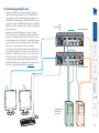
1
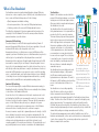
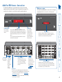
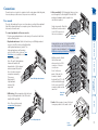
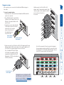
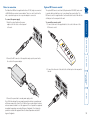
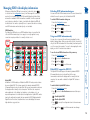
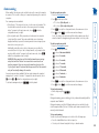
Connections The ports that make up the user console are where you attach the peripherals that will be shared between the computer systems. Ensure that power is disconnected from the unit. To connect peripherals to the user console 1 Position your peripheral devices in the vicinity of the unit such that their cables will easily reach. 2 Keyboard and mouse: Attach the leads from your USB keyboard and mouse to the USB sockets specifically labelled with keyboard and mouse symbols. The keyboard and mouse will operate in any of the USB sockets, however, True Emulation is not available on sockets labelled USB1 or USB2. Note: These sockets provide enumerated (transparent) switching. OP T US E CO R NS OL E From USB keyboard and mouse 4 3 5V 2 US U SWSB2.0 ITC HE D US B1 4A US E CO R NS O LE 1 From video monitors 1 Multiscreen units: Attach the lead from each video monitor to a DVI-I connector of the user console area. Note: On the rear panel of the unit, the connectors at each horizontal level (V1 to V4) will be switched through to the user console DVI-I connector which is at the same level. During initial power up, the AdderView PRO unit will attempt to read the EDID information from the connected display(s). See Managing EDID video display information for details. OP TIO NS 3 USB devices: Where required, attach the leads from your USB peripherals to the USB sockets labelled USB1 and USB2. Single screen units: Attach the lead from the video monitor to the DVI-I connector of the user console area. US E CO R NS OL E 5 Audio: Where required, connect the lead from your speakers to the audio socket. B2 OP T Note: The unit’s True Emulation feature will read the full characteristics of the keyboard and mouse and will present those to each connected computer concurrently. This ensures that specialist keyboards and mice are fully supported. 2A From video monitor 5V 2A 5V User console 4 Video monitor(s): DVI-I (integrated) video ports are used throughout to allow digital DVI and/or VGA analogue (via adapter cables) signals to be switched, as required. 5V 2A Connections do not need to be carried out in the order given within this guide, however, where possible connect the power in as a final step. US E CO R NS OL E OP T From USB peripherals From speakers