1
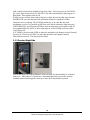
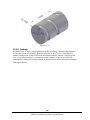
Note - Maximum work capacities are dependent on a lot of variables that cannot be controlled by the machine manufacturer. Each one of the following will have an impact on the above numbers: speeds, feeds, cutter, cutter sharpness, material, setup, coolant and machine adjustments. 3.3.4 Electrical Cabinet The electrical cabinet is found at the rear of the LPM on the right side. The electrical cabinet contains the main control hardware for the machine. The main components are as follows: computer module, AC spindle drive, servo drives, input/output modules, relays and contactors. 3.3.5 Computer Module The computer module is the heart and soul of the machine. All of the inputs and outputs are feed through this module. The computer module controls the program panel, run panel, AC spindle drive, servo drives, motor signals and feedback and input/output modules. Inside of the computer module is a motherboard, motion control board and an applications board along with a power supply. The computer module also contains 4 more USB ports and a network port. We ship the machine with 3 USB ports having something plugged into them. The 3 USB ports contain the following: machine option key, a D drive for part storage and an overlay interface USB cable. The network port is available to the user if they want to network the control to an offline computer or network. 3.3.6 Servo Motors The LPM can run up to 4 axis motors. The 4th motor would be used to control a 4th axis indexer. The motors used on the X and Y axis are rated for 4.2 ft/lbs of torque. The Z axis motor is rated at 8.11 ft/lbs and also contains a mechanical brake the holds the head in position when the power is turned off to the machine. 3.3.7 Servo Drives The LPM can also contain up to 4 servo drives. The 4th amp would be used to control a 4th axis indexer or rotary table. The servo drives receive signals from the computer module, which in turn send signals to the servo motors. 3.3.8 Spindle The spindle is contained within a cartridge and CAT 40 tool holders must be used. The spindle bearings are permanently lubricated and require no additional attention by the user. The spindle is also air cooled, and has an air purge system that is automatically activated during the tool change sequence, it blows air down the spindle to prevent chips from being trapped between the holder and spindle taper. Warning! The spindle unit is not field serviceable. If the bearings go bad the entire spindle cartridge will be replaced. 22 Southwestern Industries, Inc. TRAK LPM Programming, Safety, & Operating Manual