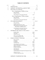
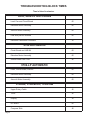
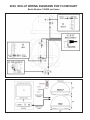
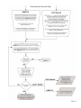
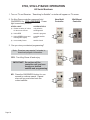
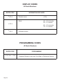
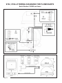
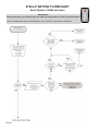
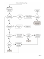
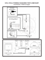
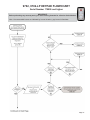
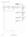
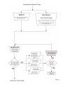
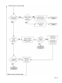
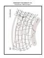
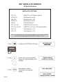
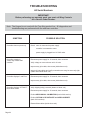
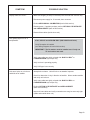
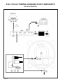
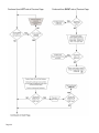
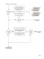
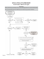
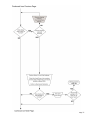
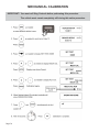
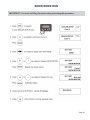
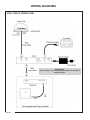
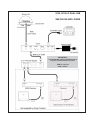
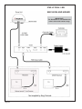
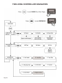
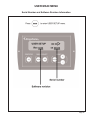
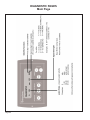
1
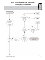
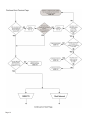
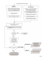
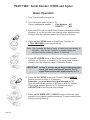
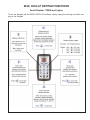
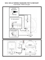
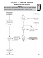
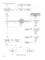
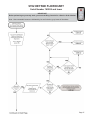
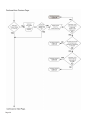
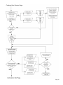
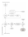
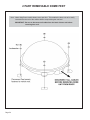
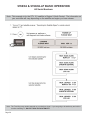
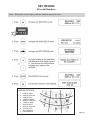
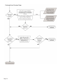
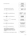
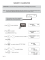
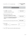
Troubleshooting Guide
TM
Satellite Solutions for Mobile Markets
11200 Hampshire Avenue South, Bloomington, MN 55438-2453
Phone: (800) 982-9920
Fax: (952) 922-8424
www.kingcontrols.com
1305 TROUBLESHOOTING GUIDE REV E
DIRECTV is a registered trademark of DIRECTV, Inc.
Dish Network® is an official trademark of Echostar Communications Corporation.
Bell ExpressVu® is an official trademark of Bell Canada.
DVB® is a trademark of the DVB Digital Video Broadcast Project (1991-1996)
TABLE OF CONTENTS
Section
Contents
Page
1.
INTRODUCTION . . . . . . . . . . . . . . . . . . . . . . . . . . . . . . . . . . . . . . .2
2.
WARRANTY INFORMATION and BLOCK TIMES . . . . . . . . . . . .3-4
3.
9630 & 9630-LP AUTOSCAN . . . . . . . . . . . . . . . . . . . . . . . . . . .7-19
Part 1: Serial Number 169999 and lower
Basic Operation . . . . . . . . . . . . . . . . . . . . . . . . . . . . . . . . . . . .8
Keypad Functions . . . . . . . . . . . . . . . . . . . . . . . . . . . . . . . . . . .9
Wiring Diagrams and Keypad Flowcharts . . . . . . . . . . . . .10-13
Part 2: Serial Number 170000 and higher
Basic Operation . . . . . . . . . . . . . . . . . . . . . . . . . . . . . . . . . . .14
Keypad Functions . . . . . . . . . . . . . . . . . . . . . . . . . . . . . . . . . .15
Wiring Diagrams and Keypad Flowcharts . . . . . . . . . . . . .16-19
4.
9702 & 9702-LP AUTOMATIC . . . . . . . . . . . . . . . . . . . . . . . . . .21-41
Basic Operation . . . . . . . . . . . . . . . . . . . . . . . . . . . . . . . . . . .22
Keypad Functions . . . . . . . . . . . . . . . . . . . . . . . . . . . . . . . . . .23
Display and Programming Codes . . . . . . . . . . . . . . . . . . . . . .24
Wiring Diagrams and Keypad Flowcharts . . . . . . . . . . . . .26-35
Serial Number 169999 and lower
Wiring Diagrams and Keypad Flowcharts . . . . . . . . . . . . .36-41
Serial Number 170000 and higher
5.
REFERENCE: 9630, 9630-LP & 9702, 9702-LP . . . . . . . . . . .43-54
Elevation Maps . . . . . . . . . . . . . . . . . . . . . . . . . . . . . . . . .44-46
Zone Maps . . . . . . . . . . . . . . . . . . . . . . . . . . . . . . . . . . . . .48-51
Definition of Terms . . . . . . . . . . . . . . . . . . . . . . . . . . . . . . . . .52
Direct to Circuit Board Cable . . . . . . . . . . . . . . . . . . . . . . . . .53
2 Part Removable Dome Feet . . . . . . . . . . . . . . . . . . . . . . . .54
6.
9760/62 & 9760/62-LP TRAC-KING . . . . . . . . . . . . . . . . . . . . .57-93
Basic Operation . . . . . . . . . . . . . . . . . . . . . . . . . . . . . . . . . . .58
Set Region . . . . . . . . . . . . . . . . . . . . . . . . . . . . . . . . . . . . . . .59
Set Satellite . . . . . . . . . . . . . . . . . . . . . . . . . . . . . . . . . . . .60-61
Troubleshooting . . . . . . . . . . . . . . . . . . . . . . . . . . . . . . . . .62-63
Wiring Diagrams and Flowcharts . . . . . . . . . . . . . . . . . . . .64-72
Option 21 Re-initialize and 0-Recalibrate . . . . . . . . . . . . .74-75
Magnetic Calibration . . . . . . . . . . . . . . . . . . . . . . . . . . . . .76-77
Mechanical Calibration . . . . . . . . . . . . . . . . . . . . . . . . . . . . . .78
Show Mode Run . . . . . . . . . . . . . . . . . . . . . . . . . . . . . . . . . . .79
Wiring Diagrams . . . . . . . . . . . . . . . . . . . . . . . . . . . . . . . .80-83
Trac-King Controller Navigation and Diagnostic Pages . .84-90
Definition of Terms . . . . . . . . . . . . . . . . . . . . . . . . . . . . . . . . .91
2 Part Removable Dome Feet . . . . . . . . . . . . . . . . . . . . . . . .92
WARRANTY CONSIDERATION FORM . . . . . . . . . . . . . . . . . . . . .96
SECTION 1
INTRODUCTION
The King Controls Service Department is dedicated
to providing its dealers and customers
with the highest possible level of satisfaction and service.
Welcome to King Controls.
The satellite TV market is expanding and changing. The King Controls Service Department stays
up to date with the latest information to assist you in keeping troubleshooting and repair time to a
minimum.
When calling our service department, a King-Dome technician will issue a Service Order Number
and then clearly define the proper course of action to follow. Additionally, the King-Dome
technician will create a call log to aid in properly documenting the warranty claim.
Remember, for warranty reimbursement, you must call King Controls for a Service Order
Number before performing any work.
Page 2
SECTION 2
WARRANTY INFORMATION
Every King Controls Satellite System is covered by a TWO YEAR PARTS AND ONE YEAR LABOR limited
warranty from the date of original purchase.
This warranty does not cover installation and external wiring, or refurbished units. This warranty also does not apply
where:
• The product has been abused, misused, improperly installed or improperly maintained.
• Repairs have been made or attempted by others that are not certified by King Controls to do such repairs.
• Repairs are required because of normal wear and tear.
• Alterations have been made to the product.
PROCESSING A WARRANTY CLAIM
Note: Only King Controls certified dealers are authorized to perform warranty evaluations and repairs.
1) Technician must first determine if the unit is under warranty by verifying original owner and date of original
purchase. Dealer must provide one of the following when submitting a warranty claim:
• copy of original purchase receipt, or
• if unit was installed by an OEM, verification of in-service date
2) Technician must call King Controls to get a Service Order Number (1-800-982-9920).
TECHNICIAN MUST NOT PROCEED WITHOUT A SERVICE ORDER NUMBER.
• A King-Dome technician will issue a Service Order Number and advise technician on how to proceed.
3) After repairs are completed, the following must be sent to King Controls:
•
•
•
•
Defective Part (Warranty Labor Claim will not be processed until part is returned.)
Warranty Consideration Form
Copy of Work Order
Proof of Purchase
KEY POINTS
1) Technician must have the proper King-Dome Diagnostic Tool.
2) For units in service longer than one year, the customer is responsible for labor time.
3) Installation parts (coax, power and data cables, etc.) are not covered.
4) Replacement parts (including domes) are sent directly from King Controls. DO NOT USE NEW PRODUCT
FOR WARRANTY REPLACEMENT WITHOUT WRITTEN AUTHORIZATION FROM KING CONTROLS.
5) Technician must call King Controls before performing any work for which warranty labor reimbursement will
be submitted to King Controls. A King-Dome technician will issue a Service Order Number and specify the
allotted time for the repair. If repairs will take longer than the allotted time, and the servicing dealer wishes
to receive proper reimbursement, the technician must receive prior authorization to exceed the allotted time.
6) Warranty claims must include: proof of purchase, Warranty Consideration Form with Service Order Number,
and copy of work order with labor time which matches that allotted by King Controls.
7) King Controls shall reimburse the servicing dealer for warranty work at their published labor rates.
8) Enclose paperwork with defective part. Clearly mark the Service Order Number on outside of box.
Page 3
TROUBLESHOOTING BLOCK TIMES
Time is listed in minutes.
9630, 9630-LP AUTOSCAN
Level Can and Circuit Board
60
Elevation Motor Assembly
60
Azimuth Motor Assembly
60
LNB with position marked
60
Elevation Calibration Procedure
30
9702 AUTOMATIC
Circuit Board and LNB Kit
60
Elevation Motor Assembly
60
Internal Main LNB Coax
45
9702-LP AUTOMATIC
Level, Circuit Board, LNB Kit
60
Elevation Motor Assembly
60
Azimuth Motor Assembly
60
9760/62, 9760/62-LP, 9762-SW
Page 4
Upper Rotary Cable
45
Tuner
45
Display
30
RF Board
60
Compass Stick
45
This page intentionally left blank.
Page 5
This page intentionally left blank.
Page 6
Section 3
AUTOSCAN
9630, 9630-LP
IMPORTANT! Some of the 9630 and 9630-LP functions have changed slightly starting
with serial number 170000. This section is divided into two parts
corresponding to the two serial number ranges.
Please make sure you are using the correct procedure for the serial
number of the unit you are working on. Each procedure notes the serial
number range at the top of the page.
Note: For more detailed installation information, please refer to the 9630 & 9630-LP
Installation and Operating Instructions Manual available on our website at
www.kingcontrols.com.
Page 7
PART ONE: Serial Number 169999 and lower
Basic Operation
1. Turn TV and satellite receiver on.
2. Go to the signal meter screen on TV.
Choose transponder number:
Dish Network #11
DIRECTV
#19
3. Enter local zip code on signal meter screen to determine satellite
elevation. If you do not know your local zip code, determine your
elevation from the elevation maps in the Reference Section.
4. Press UP arrow on King-Dome Controller to turn King-Dome on.
Note: The King-Dome Controller will count down from 99 to 00
and then display OH.
5. Press UP or DOWN arrow on King-Dome Controller to display dish
elevation and match to elevation on TV signal meter screen or
elevation from the elevation maps in the Reference Section.
IMPORTANT! In Step 6, as soon as you begin holding the right
arrow, you must continuously monitor the TV
signal meter screen until signal appears on TV.
6. Press and hold RIGHT arrow until Controller begins flashing “77.”
Remember, you must watch for signal strength on TV!
Dish will automatically perform a 360 degree scan for satellite.
When signal strength appears on TV, momentarily press
ANY BUTTON to stop the dish from rotating.
7. Press the UP, DOWN, LEFT or RIGHT arrows to fine tune signal
strength to the highest possible number on TV signal meter
screen. Enjoy your programming!
Controller automatically shuts off after 2 minutes.
Page 8
9630, 9630-LP KEYPAD FUNCTIONS
Serial Number 169999 and lower
To use the Keypad with the 9630 & 9630-LP AutoScan, simply unplug the existing controller and
plug in the Keypad.
Page 9
9630, 9630-LP WIRING DIAGRAMS FOR FLOWCHART
Serial Number 169999 and lower
Page 10
9630, 9630-LP KEYPAD FLOWCHART
Serial Number 169999 and lower
IMPORTANT!
Before performing any warranty work, you must call King Controls for a Service Order Number.
Note: Non-warrantable issues are indicated by, but not limited to, grey boxes in flowcharts.
Page 11
Page 12
Page 13
PART TWO: Serial Number 170000 and higher
Basic Operation
1. Turn TV and satellite receiver on.
2. Go to the signal meter screen on TV.
Choose transponder number:
Dish Network
DIRECTV
#11
#19
3. Enter local ZIP code on signal meter screen to determine satellite
elevation. If you do not know your local zip code, determine your
elevation from the elevation maps in the Reference Section.
4. Press and hold UP/ON arrow on King-Dome Controller for
3 FULL SECONDS to turn King-Dome on.
Note: The Controller will flash a series of codes and then display its
elevation. Wait for the Controller to steadily display the
elevation before continuing (about 10 seconds).
5. Press UP or DOWN arrow on King-Dome Controller to match
elevation on Controller to elevation on TV signal meter screen or
elevation from the elevation maps in Reference Section.
IMPORTANT! In Step 6, as soon as you begin holding the right
arrow, you must continuously monitor the TV
signal meter screen until signal appears on TV.
6. Press and hold RIGHT arrow until Controller begins RAPIDLY
flashing its clock position (7-10 seconds).
Remember, you must watch for signal strength on TV!
Dish will automatically perform a 360 degree scan for satellite.
When signal strength appears on TV, momentarily press
ANY BUTTON to stop the dish from rotating.
7. Press the UP, DOWN, LEFT or RIGHT arrows to fine tune signal
strength to the highest possible number on TV signal meter screen.
Enjoy your programming!
Page 14
9630, 9630-LP KEYPAD FUNCTIONS
Serial Number 170000 and higher
To use the Keypad with the 9630 & 9630-LP AutoScan, simply unplug the existing controller and
plug in the Keypad.
Page 15
9630, 9630-LP WIRING DIAGRAMS FOR FLOWCHART
Serial Number 170000 and higher
Page 16
9630, 9630-LP KEYPAD FLOWCHART
Serial Number 170000 and higher
IMPORTANT!
Before performing any warranty work, you must call King Controls for a Service Order Number.
Note: Non-warrantable issues are indicated by, but not limited to, grey boxes in flowcharts.
Page 17
Page 18
Page 19
This page intentionally left blank.
Page 20
Section 4
AUTOMATIC
9702, 9702-LP
IMPORTANT! Some of the 9702 and 9702-LP functions have changed slightly starting
with serial number 170000. Please make sure you are using the correct
procedure for the serial number of the unit you are working on. Each
procedure notes the serial number range at the top of the page.
Note: For more detailed installation information, please refer to the 9702 & 9702-LP
Installation and Operating Instructions Manual available on our website at
www.kingcontrols.com.
Page 21
9702, 9702-LP BASIC OPERATION
All Serial Numbers
1. Turn on TV and Receiver. “Searching for Satellite” or similar will appear on TV screen.
2. On King Dome controller, press and hold
ON/SEARCH for 3 FULL SECONDS. Power
light turns steady GREEN.
STATUS LIGHT
a) flashes a variety of colors
for about one minute
SYSTEM STATUS
unit performs
self-diagnostic
b)
blinks RED
search in progress
c)
blinks GREEN (may start
blinking RED again)
potential satellite
found
d)
turns steady Green
satellite found
3. Can you view your desired programming?
Note: Receiver may require 2 minutes to
download program information.
YES: Turn King-Dome off and enjoy.
IMPORTANT! Do not turn off the
controller until you have
found your desired
satellite and programming.
NO: Press the ON/SEARCH button for one
second to continue search. Repeat
step until you are locked onto the
correct satellite.
Page 22
Hand Held
Controller
Wall Mount
Controller
9702 & 9702-LP KEYPAD FUNCTIONS
All Serial Numbers
To use the Keypad with the 9702 & 9702-LP Automatic, simply unplug the existing controller and
plug in the Keypad.
Page 23
DISPLAY CODES
All Serial Numbers
ENTER CODE
*
80 #
*
82 #
*
98 #
INFORMATION DISPLAYED
Elevation zone
(1-16)
Mode
45 = 15” automatic
55 = 15” manual
65 = 12” automatic
75 = 12” manual
Software revision
PROGRAMMING CODES
All Serial Numbers
ENTER CODE
* 01 #
Page 24
thru
* 16 #
PROGRAMMING
Programs Elevation zone (see Zone Maps in Reference Section).
This page intentionally left blank.
Page 25
9702, 9702-LP WIRING DIAGRAMS FOR FLOWCHARTS
Serial Number 169999 and lower
Page 26
9702 KEYPAD FLOWCHART
Serial Number 169999 and lower
IMPORTANT!
Before performing any warranty work, you must call King Controls for a Service Order Number.
Note: Non-warrantable issues are indicated by, but not limited to, grey boxes in flowcharts.
Page 27
Page 28
Page 29
Page 30
Page 31
9702-LP KEYPAD FLOWCHART
Serial Number 169999 and lower
IMPORTANT!
Before performing any warranty work, you must call King Controls for a Service Order Number.
Note: Non-warrantable issues are indicated by, but not limited to, grey boxes in flowcharts.
Page 32
Page 33
Page 34
Page 35
9702, 9702-LP WIRING DIAGRAMS FOR FLOWCHART
Serial Number 170000 and higher
Page 36
9702, 9702-LP KEYPAD FLOWCHART
Serial Number 170000 and higher
IMPORTANT!
Before performing any warranty work, you must call King Controls for a Service Order Number.
Note: Non-warrantable issues are indicated by, but not limited to, grey boxes in flowcharts.
Page 37
Page 38
Page 39
Page 40
Page 41
This page intentionally left blank.
Page 42
Section 5
REFERENCE
9630, 9630-LP
9702, 9702-LP
Page 43
ELEVATION MAP FOR DIRECTV 101
All Serial Numbers
Page 44
ELEVATION MAP FOR DISH NETWORK 110
All Serial Numbers
Page 45
ELEVATION MAP FOR DISH NETWORK / DIRECTV 119
All Serial Numbers
Page 46
This page intentionally left blank.
Page 47
ZONE MAP FOR DIRECTV 101
Serial Number 169999 and lower
Page 48
ZONE MAP FOR DIRECTV 101
Serial Number 170000 and higher
Page 49
ZONE MAP FOR DISH NETWORK 119
Serial Number 169999 and lower
Page 50
ZONE MAP FOR DISH NETWORK 119
Serial Number 170000 and higher
Page 51
DEFINITION OF TERMS
9630, 9630-LP, 9702, 9702-LP All Serial NUmbers
AZIMUTH: Circular rotation around the vehicle.
Like a clock face: front of vehicle is 12:00, rear is 6:00.
ELEVATION: Angle in degrees measured from the ground plane.
Page 52
DIRECT TO CIRCUIT BOARD CABLE
9630, 9630-LP, 9702, 9702-LP All Serial Numbers
IMPORTANT! Only the Direct to Circuit Board Cable will work for this procedure. A
standard phone cord WILL NOT WORK.
Call King Controls before performing this procedure.
Note: Warranty does not cover external wiring.
The Direct to Circuit Board Cable (supplied by King Controls) is used to verify that the data cable
in the external wire harness is good.
Leave the external wire harness connected to the back of the dome unit.
Connect the Direct to Circuit Board Cable between the Keypad and the circuit board and press
ON. The Keypad should turn on.
Page 53
2 PART REMOVABLE DOME FEET
Note: Newer King-Dome models feature a two part foot. This enables the dome unit to be easily
removed from the roof of the vehicle without compromising the roof seal.
IMPORTANT! Be sure to disconnect all cables from the back of dome unit before
removing from roof.
Page 54
This page intentionally left blank.
Page 55
This page intentionally left blank.
Page 56
Section 6
TRAC-KING
9760, 9762
9760-LP, 9762-LP
IMPORTANT! Some of the 9762 and 9762-LP functions have changed slightly starting
with serial number 362652. Please make sure you are using the correct
procedure for the serial number of the unit you are working on. Each
procedure notes the serial number range at the top of the page.
Note: For more detailed installation information, please refer to the 9760/62 and 9760/62-LP
Installation and Operating Instructions Manual available on our website at
www.kingcontrols.com.
Page 57
9760/62 & 9760/62-LP BASIC OPERATION
All Serial Numbers
Note: This example is for the DTV 101 satellite in Region 2-North Central. The information on
your controller will vary depending on the satellite and region you have chosen.
Note: The Trac-King must remain powered on to maintain a signal. If you are going to be stationary and wish to
continue watching TV, DO NOT TURN THE SYSTEM OFF.
Page 58
SET REGION
All serial Numbers
Note: Setting the current region reduces satellite acquisition time.
REGION OPTIONS:
1
2
3
4
5
6
7
8
9
0
NORTH WEST
NORTH CENTRAL
NORTH EAST
CENTRAL WEST
MIDDLE CENTRAL
CENTRAL EAST
SOUTH WEST
SOUTH CENTRAL
SOUTH EAST
ALL REGIONS
RECALIBRATE
Page 59
SET SATELLITE SERVICE
All Serial Numbers
SATELLITE OPTIONS
DTV 101
DIRECTV at 101 West Longitude
EXPVU 82
Bell ExpressVu at 82
Dish 148
Dish Network at 148
EXPVU 91
Bell ExpressVu at 91
Dish 61
Dish Network at 61
DTV 101/119
DIRECTV at 101 and 119
DTV 101/110 HD
DIRECTV at 101 and 110 (High Definition)
SAT 119
Dish Network at 119
SAT 110
Dish Network at 110
Note: The King Controls HD TV Converter Box (#9747 or #9747-AM) is required
to receive HD programming from the DIRECTV satellite at 110 W.
Page 60
Note: For DIRECTV Subscribers: The satellite setting allows the user to select the satellite
and service provider of choice. For DIRECTV subscribers, the Trac-King can also track
a secondary or alternate satellite.
Example: If you are a subscriber to the DIRECTV service most of the programming that
you will be watching will be transmitted from the satellite located at 101 degrees. You
may also subscribe to programming that is transmitted from another satellite located at
119 degrees. In order to receive programming from both satellites you can either select
an individual (DTV 101) satellite manually from the display or you can select a multiple
(DTV 101/119) satellite setup. The multiple satellite selection will automatically switch
between satellites (DTV 101/119) based on the channel or programming that you select
on the Satellite Receiver (multi-satellite capable receiver is required). Please keep in
mind that the programming may pause (freeze frame) or pixelate while the antenna
acquires and locks onto the new satellite.
The multiple satellite setting will work only if your satellite receiver is set up to work in
oval dish mode. Consult your satellite receiver manual for instruction.
It is not recommended to use the DTV 101/119 setting unless there is programming on
the DTV 119 satellite that you specifically subscribe to.
For Dish Network Subscribers: Use the procedure on the previous page to switch
between the 110 and 119 satellites.
Page 61
TROUBLESHOOTING
All Serial Numbers
IMPORTANT!
Before performing any warranty work, you must call King Controls
for a Service Order Number.
Note: The Keypad is not used with the Trac-King product line. All diagnostics and
troubleshooting are performed with the end-user controller.
SYMPTOM
Controller does not power up.
POSSIBLE SOLUTION
Check: tuner is connected to power supply.
controller is connected to tuner.
power supply is plugged into 110 VAC outlet.
Controller remains in
“Power Up, Please Wait”
condition.
Disconnect power supply for 15 seconds, then reconnect.
Verify voltage on coax at dome unit is 24 volts.
Inspect rotary joint cable, then reseat (inside dome unit).
Inspect all coax cables and verify connections are snug but not overly tight
(inside and outside dome unit).
Controller displays “Load Error.”
Disconnect power supply for 15 seconds, then reconnect.
Inspect rotary joint cable, then reseat (inside dome unit).
Controller displays “AZ FAULT.”
Dish cannot rotate.
Verify shipping bolt(s) removed (bottom of dome unit).
Disconnect power supply for 15 seconds, then reconnect.
Perform MECHANICAL CALIBRATION (back of this section).
Perform OPTION 21 RE-INITIALIZE and 0-RECALIBRATE
(back of this section).
Reseat ribbon cables (inside dome unit).
Page 62
SYMPTOM
Display reads “EL FAULT.”
POSSIBLE SOLUTION
Make sure shipping tie strap is removed (back left hand side of dome unit).
Disconnect power supply for 15 seconds, then reconnect.
Perform MECHANICAL CALIBRATION (back of this section).
Restart system. If problem persists, perform OPTION 21 RE-INITIALIZE
and 0-RECALIBRATE (back of this section).
Reseat ribbon cables (inside dome unit).
Only getting signal on 1/2 of
transponders.
9762 / 9762-LP and 9762-SW ONLY (SN# 360325 and lower):
Verify De-stacker is installed
(see Wiring Diagrams in back of this section).
IMPORTANT! The De-stacker must be installed even if only one
TV and receiver are used.
Verify coax cables are tightly crimped with SNAP ‘N’ SEAL® or
F-COMPRESSION style crimps only.
Verify receiver is operating properly.
Verify LNB type is set correctly.
Unit never locks on or locks on
and drifts off of satellite.
Atmospheric moisture. Unit will lock on as weather improves.
Check for obstruction in sky in direction of satellite. Select another satellite
and verify unit locks on.
Verify coax cables are tightly crimped with SNAP ‘N’ SEAL® or
F-COMPRESSION style crimps only.
Perform OPTION 21 RE-INITIALIZE and 0-RECALIBRATE
(back of this section).
Inspect all coax cables and verify connections are snug but not overly tight
(inside and outside dome unit).
Page 63
9762, 9762-LP WIRING DIAGRAMS FOR FLOWCHARTS
All Serial Numbers
Page 64
9762, 9762-LP FLOWCHART
Serial Number 362651 and lower
IMPORTANT!
Before performing any warranty work, you must call King Controls for a Service Order Number.
Note: Non-warrantable issues are indicated by, but not limited to, grey boxes in flowcharts.
Page 65
Page 66
Page 67
9762 & 9762-LP FLOWCHART
Serial Number 362652 and higher
IMPORTANT!
Before performing any warranty work, you must call King Controls for a Service Order Number.
Note: Non-warrantable issues are indicated by, but not limited to, grey boxes in flowcharts.
Page 68
Page 69
Page 70
Page 71
Page 72
This page intentionally left blank.
Page 73
OPTION 21 RE-INITIALIZE AND 0-RECALIBRATE
IMPORTANT! You must call King Controls before performing this procedure.
Page 74
Page 75
MAGNETIC CALIBRATION
IMPORTANT! You must call King Controls before performing this procedure.
Note: To check if a Magnetic Calibration has been performed, go to Diagnostic Page H (see
TRAC-KING CONTROLLER NAVIGATION at the back of this section).
H 5
Ms, -2234,0
If this number is zero, then a magnetic
calibration has not been performed.
Page 76
X15
IMPORTANT! During Step 7, DO NOT MOVE THE VEHICLE.
Page 77
MECHANICAL CALIBRATION
IMPORTANT! You must call King Controls before performing this procedure.
The vehicle must remain completely still during this entire procedure.
Page 78
SHOW MODE RUN
IMPORTANT! You must call King Controls before performing this procedure.
Page 79
WIRING DIAGRAMS
9760, 9760-LP SINGLE LNB
IMPORTANT!
The De-stacker is not installed with the 9760 and 9760-LP
single LNB unit.
Page 80
9762, 9762-LP DUAL LNB
SN# 360325 AND LOWER
IMPORTANT!
The De-stacker must be installed even if
only one TV and receiver are used.
9762-LP = 4 Port
9762 = 2 Port
Page 81
9762-LP DUAL LNB
SN# 360326 AND HIGHER
IMPORTANT!
The De-stacker is not installed with
units in this serial number range.
Page 82
HDTV CONVERTOR BOX
SINGLE LNB / DUAL LNB
Note:
For multiple receiver hookups, see
HDTV Convertor Box Instructions,
available at www.kingcontrols.com
Page 83
TRAC-KING CONTROLLER NAVIGATION
Page 84
USER MAIN MENU
Serial Number and Software Revision Information
Page 85
DIAGNOSTIC PAGES
Main Page
Page 86
DIAGNOSTIC PAGES
A Page
Page 87
DIAGNOSTIC PAGES
B Page
Page 88
DIAGNOSTIC PAGES
D Page
Page 89
DIAGNOSTIC PAGES
H Page
Page 90
DEFINITION OF TERMS
AZIMUTH: Angle in degrees measured clockwise from Magnetic North (0°).
ELEVATION: Angle in degrees measured from the ground plane.
Page 91
2 PART REMOVABLE DOME FEET
Note: Newer King-Dome models feature a two part foot. This enables the dome unit to be easily
removed from the roof of the vehicle without compromising the roof seal.
IMPORTANT! Be sure to disconnect all cables from the back of dome unit before
removing from roof.
Page 92
Notes:
Page 93
Notes:
Page 94
Notes:
Page 95
WARRANTY CONSIDERATION FORM
Service Center Name
Customer Name *
Address
King-Dome® Serial Number *
(located on base of King-Dome
or on cover of Owner’s Manual)
Date of Original Purchase or Installation *
Phone No.
Make, Model and Year of Vehicle
Name and Title of person working on King-Dome®
Phone Log Number
King-Dome®
Service Order Number *
* REQUIRED
Repair Date(s)
Total Labor Time (Hours)_________
Return Shipping Charges
(Ground Only)
@ Hourly Rate of _______________
Description of Failure and Work Performed _ _ _ _ _ _ _ _ _ _ _ _ _ _ _ _ _ _ _ _ _ _ _ _ _ _ _ _ _ _ _ _ _ _ _ _ _ _
_____________________________________________________________
_____________________________________________________________
_____________________________________________________________
_____________________________________________________________
_____________________________________________________________
The following paperwork must be sent to King Controls for warranty reimbursement
consideration:
1) Warranty Consideration Form with Service Order Number
2) Copy of Work Order
3) Proof of Purchase (Sales receipt or verification of in-service date)
Note: If returning defective part, please include with paperwork. Warranty Labor Claim will not be processed until
part is returned.
TM
11200 Hampshire Ave. So.
Bloomington, MN 55438
www.kingcontrols.com
Phone (952) 922-6889
(800) 982-9920
Fax (952) 922-8424
11200 Hampshire Avenue South, Bloomington, MN 55438-2453
Phone: (800) 982-9920
Fax: (952) 922-8424
www.kingcontrols.com