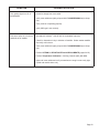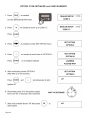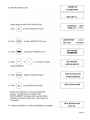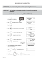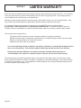
1
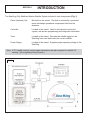
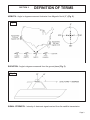
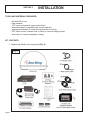
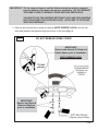
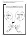
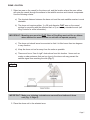
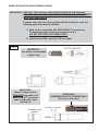
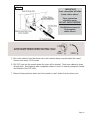
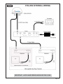
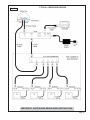
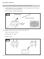
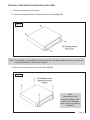
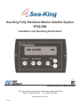
Sea-King Fully Stabilized Marine Satellite System
9762-SW
Installation and Operating Instructions
MEMBER
TM
Satellite Solutions for Mobile Markets
11200 Hampshire Avenue South, Bloomington, MN 55438-2453
Phone: (800) 982-9920
Fax: (952) 922-8424
www.kingcontrols.com
1350 REV M
IMPORTANT!
The satellite TV market is expanding and changing. The information in this manual was
accurate at the time of printing. If your Sea-King System does not operate as outlined
in this manual please call King Controls at (800) 982-9920 or visit our website at
www.kingcontrols.com.
TABLE OF CONTENTS
Section
Contents
Page
1. INTRODUCTION.....................................................................................2
2. DEFINITION OF TERMS ........................................................................3
3. INSTALLATION ..................................................................................4-17
4. OPERATION ....................................................................................18-21
5. TROUBLESHOOTING.....................................................................22-26
6. MAINTENANCE ....................................................................................27
7. LIMITED WARRANTY ..........................................................................28
ELECTRICAL HAZARD WARNING!
The coaxial cable that connects the dome
unit to the tuner carries a 24 volt electrical
current. Exercise extreme caution when
handling this cable. Do not cut, break, or
splice this line. Do not insert or connect
any devices such as splitters or any other
device for any reason. This line is not
compatible with any other equipment.
Damage will occur to any device other than
the dome unit if connected to the antenna
port on the tuner.
DIRECTV is a registered trademark of DIRECTV, Inc.
Dish Network® is an official trademark of Echostar Communications Corporation.
Bell ExpressVu® is an official trademark of Bell Canada.
DVB® is a trademark of the DVB Digital Video Broadcast Project (1991-1996)
Page 1
SECTION 1
INTRODUCTION
The Sea-King Fully Stabilized Marine Satellite System includes 4 main components (Fig. 1).
Dome (Antenna) Unit
Mounted on the vessel. The dish is covered by a protective
dome that keeps operational components free from the
elements.
Controller
Located in the vessel. Used to activate and monitor the
system, and access programming and diagnostic information.
Tuner
Located in the vessel. Decodes the satellite signal so the
Sea-King locks onto and tracks the correct satellite.
Power Supply
Located in the vessel. Supplies proper operating voltage to the
Sea-King.
Note: A TV, satellite receiver, and program subscription are also required for satellite TV
viewing. (Not supplied by King Controls.)
Fig. 1
King-Dome
START/STOP
Page 2
DISPLAYSELECT
MODIFY
SECTION 2
DEFINITION OF TERMS
AZIMUTH: Angle in degrees measured clockwise from Magnetic North (0°) (Fig. 2).
Fig. 2
ELEVATION: Angle in degrees measured from the ground plane (Fig. 3).
Fig. 3
SIGNAL STRENGTH: Intensity of electronic signal received from the satellite transmission.
Page 3
SECTION 3
INSTALLATION
TOOLS AND MATERIALS REQUIRED:
-
drill and drill bit set
tape measure
7/16” open end wrench (coax connections)
adhesive sealant (compatible with vessel material)
appropriate fasteners to install all components and wiring
5/32” allen wrench, channel lock or pliers (to remove shipping bolts)
wire cutter (to remove shipping tie strap)
KIT CONTENTS:
1. Unpack and identify all components (Fig. 4).
Fig. 4
Page 4
IMPORTANT! The tie strap and spacer, and the bolts and washers must be removed
from the bottom of the dome unit prior to installation. DO NOT REMOVE
THE DOME COVER TO REMOVE THESE SHIPPING RESTRAINTS.
YOU MUST PLUG THE SHIPPING RESTRAINT HOLE AND TWO SHIPPING
BOLT HOLES WITH THE SUPPLIED PLUGS. (ATTACHED TO TIE STRAP
SHIPPING RESTRAINT.)
2. Remove and discard the tie strap and spacer (KEEP RUBBER PLUGS), and the two
bolts and washers that pass through the bottom of the base (Fig. 5).
Fig. 5
DO NOT REMOVE DOME COVER
IMPORTANT!
Remove and discard Tie Strap and
Plastic Spacer prior to installation.
KEEP RUBBER PLUGS.
IMPORTANT!
Remove and discard
Bolts and Washers
prior to installation.
Page 5
3. Insert provided plugs into holes that were occupied by tie strap and shipping bolts.
Inserted plugs should be flush with base (Fig. 6).
Fig. 6
IMPORTANT!
After removing shipping restraints, firmly insert plugs into
appropriate holes. Plugs should be flush with base.
Page 6
DOME LOCATION
1. Select an area on the vessel for the dome unit, and the location where the coax cables
will enter the vessel through the surface to the satellite receiver and internal components.
Use the following criteria:
a) The shortest distance between the dome unit and the main satellite receiver is most
desirable.
b) The dome unit requires either: 1) a 28 inch diameter FLAT area on the vessel
surface for mounting with the attached feet or 2) an industry standard mount (call
King Controls for more information).
IMPORTANT! Mounting area must be FLAT. Base of Sea-King must not flex or deform
when attached to vessel surface or unit will not operate properly.
c) The dome unit should never be mounted so that it is tilted more than two degrees
in any direction.
d) Keep the dome unit as far away from the radar as possible.
e) There must be no “line of sight” obstructions from this location. Items such as
masts or radar antennas that are too close to the dome unit may prevent the
satellite signal from reaching the dish (Fig. 7).
Fig. 7
IMPORTANT! Make sure shipping restraints are removed from bottom of dome
unit (Fig. 5, Page 5).
2. Place the dome unit in the selected area.
Page 7
COMPONENT LOCATION:
1. Select the location of the internal components using the following criteria:
a) The Controller, Tuner, and Power Supply should be in the same general vicinity of
the main satellite receiver, AND ACCESSIBLE FOR OPERATION AND
MAINTENANCE PURPOSES.
b) The Tuner should not be stacked directly on top of other electronics. If located in a
cabinet or other enclosure, make sure there is adequate ventilation around the unit.
(If using the Tuner mounting brackets see page 17.)
c) The Controller should be conveniently located for the end user. (If using the Wall
Mount Faceplate, see page 16.)
d) All components should be secured so they do not shift or bounce around during
vessel motion.
2. Place the components in the selected areas.
SYSTEM LOCATION CHECK
ELECTRICAL HAZARD WARNING!
The coaxial cable that connects the dome unit to the tuner
carries a 24 volt electrical current. Exercise extreme
caution when handling this cable. Do not cut, break, or
splice this line. Do not insert or connect any devices such
as splitters or any other device for any reason. This line is
not compatible with any other equipment. Damage will
occur to any device other than the dome unit if connected
to the antenna port on the tuner.
To verify proper operation of the components in their selected locations, perform a System
Location check as follows:
1. TEMPORARILY connect system as outlined in Fig. 10, Page 13.
2. Verify system operates properly as described in Section 4 OPERATION, Page 18.
3. After verifying proper operation of the system, disconnect all components.
Page 8
DOME INSTALLATION AND EXTERNAL WIRING
IMPORTANT! USE ONLY THE COAXIAL CABLES SUPPLIED WITH THE SEA-KING.
DO NOT CUT COAX. COIL AND STORE EXCESS CABLE IN THE CABINET
WITH THE COMPONENTS.
If coaxial cable other than that supplied with the Sea-King is used, the
following guide lines must be followed:
1) Ends must be terminated with SNAP-N-SEAL® connectors or
F-compression style connectors as shown in Fig. 8.
(DO NOT USE TWIST-ON CONNECTORS.)
2) Cable must be RG6, rated at 2.2 Ghz or higher.
Fig. 8
IMPORTANT!
Use factory recommended
stripper only.
IMPORTANT!
Rubber O-rings must be
REMOVED from ends of all
SNAP-N-SEAL® connectors
and F-compression style
connectors.
IMPORTANT!
COMPRESSION STYLE CRIMPER ONLY!
(Do not use hex style.)
Page 9
Note: The installer is responsible for determining the most appropriate fastener to secure the
dome unit to the vessel surface. Depending on the surface material, fasteners such as
lag screws, well nuts, sheet metal screws, toggle bolts and T anchors may be used, and
should always be used in combination with a surface compatible adhesive sealant.
IMPORTANT! The installer is responsible for weatherproofing all holes with sealant.
IMPORTANT! Make sure power supply is disconnected from 110 volt source before
continuing with permanent installation.
Make sure shipping restraints are removed from bottom of dome unit, and
plugs inserted in appropriate holes (Fig. 5, Page 5 and Fig. 6, Page 6).
Cable connection must ALWAYS be positioned facing the rear of vessel.
DO NOT USE THE FOUR SEALED BEARING HOLES IN THE BOTTOM OF
THE DOME UNIT FOR MOUNTING.
1. Mount the dome unit. Use the pre-drilled holes in the mounting feet as a guide to install
the fasteners into the vessel surface. Use additional fasteners whenever necessary.
2. Test that the dome unit is secure by pulling upward from each foot location.
Note: The King-Dome is wired for a dual LNB. There are two coaxial ports on the back of the
dome unit. The one labeled “MAIN” must be connected to the Tuner (IDB) in vessel.
The one labeled “AUX” can be used for an additional receiver (see page 15).
Apply non-conductive electrolytic grease to all stingers (coax cable center conductors)
before installation.
IMPORTANT! Do not remove the rubber sleeve from the coax port. The coax cable end
will slide inside the sleeve as it is tightened.
3. Connect 50’ coax cable to the coax port labeled MAIN on the back of the dome unit and
tighten connection. If using a second receiver, connect second 50’ coax cable to coax
port labeled AUX and tighten connection. DO NOT OVER TIGHTEN CONNECTIONS.
(Fig. 9).
4. Snap the gel-filled boot(s) around the coax cable(s), then push flush against the rubber
sleeve(s) on the coax port(s) (Fig. 9).
Page 10
Fig. 9
IMPORTANT!
Coax connection will slide
inside rubber sleeve.
Coax connection
should be snug.
DO NOT OVER TIGHTEN!
Gel-filled boot must sit
flush against
rubber sleeve.
5. Run coax cable(s) from the dome unit to the location where coax will enter the vessel.
Secure coax every 12-18 inches.
6. Drill 3/4” hole into the vessel where the tuner will be located. Feed coax cables(s) down
through hole. Seal opening with compatible sealant so that it is entirely waterproof (inside
and outside of the 3/4” hole).
7. Remove blue protective sheet and red “position to rear” sticker from the dome unit.
Page 11
ELECTRICAL HAZARD WARNING!
The coaxial cable that connects the dome unit to the tuner
carries a 24 volt electrical current. Exercise extreme
caution when handling this cable. Do not cut, break, or
splice this line. Do not insert or connect any devices such
as splitters or any other device for any reason. This line is
not compatible with any other equipment. Damage will
occur to any device other than the dome unit if connected
to the antenna port on the tuner.
INTERNAL WIRING (Fig. 10)
IMPORTANT! The 50’ coax from the “MAIN” port on the dome unit MUST be connected
to the Tuner (IDB) in the vessel.
Coax connections should be snug. DO NOT OVER TIGHTEN.
Note. Apply non-conductive electrolytic grease to all stingers before installation.
1. Connect the 50’ coax cable from “MAIN” on dome unit to the tuner port labeled “ANT.”
2. Connect the 7’ coax from the tuner port labeled “REC” to the main satellite receiver port
labeled “SATELLITE IN.”
3. Connect the 7’ controller cable from the controller to the tuner port labeled “IDD.”
4. If installing a second receiver, connect the 50’ coax cable from “AUX” on dome unit to the
“SATELLITE IN” port on the second receiver.
Note: Make sure the proper connections are made between the receivers and TVs.
IMPORTANT! When connecting the power supply cable to the tuner, push in the power
supply cable end until it is flush against the back of the tuner.
5. Connect the power supply cable to the tuner port labeled “PWR”.
6. Plug the power supply into a 110 VAC source.
Note: The controller should turn on for 3 seconds and then turn off. If the controller stays on,
press the ENTER and “-” button simultaneously for 3 seconds to turn unit off.
Page 12
Fig. 10
9762-SW INTERNAL WIRING
IMPORTANT! AVOID SHARP BENDS WHEN ROUTING COAX.
Page 13
MULTIPLE SATELLITE RECEIVER CONFIGURATIONS
With the use of an active multi-switch (not supplied by King Controls), more than two TV’s and
receivers can be hooked up (see Fig. 11 for typical 4 receiver hookup).
Other options:
3-4 satellite receivers: use one 2x4 or 3x4 active multi-switch
8 satellite receivers: use one 2x8 or 3x8 active multi-switch
16 satellite receivers: use one 3x16 active multi-switch
King Controls recommends the use of an active multi-switch.
Recommended brands (other brands may work as well):
Channel Master
Eagle Aspen
Perfect Vision
Spaun
Terk
Page 14
Fig. 11
TYPICAL 4 RECEIVER HOOKUP
IMPORTANT! AVOID SHARP BENDS WHEN ROUTING COAX.
Page 15
WALL MOUNT FACEPLATE
Note: If not using the Faceplate, see Faceplate removal instructions below.
1. Use the Faceplate as a guide to mark and cut out the mounting cavity, and if necessary,
mark and drill the mounting holes (Fig. 12).
2. Mount Faceplate in wall with supplied screws.
Fig. 12
Note:
Depending on the
mounting surface, pilot
holes for the screws
may or may not need to
be drilled.
The Faceplate is optional and can be removed as follows: (Fig. 13)
1. Remove 4 screws from Controller.
2. Slide Faceplate off Controller.
3. Replace 4 screws.
Fig. 13
Page 16
OPTIONAL TUNER MOUNTING BRACKETS (INCLUDED)
1. Remove 4 screws from the tuner.
2. Fasten mounting brackets to tuner with same screws (Fig. 14).
Fig. 14
Note: The installer is responsible for determining the most appropriate fasteners to secure the
mounting brackets to the chosen surface.
3. Mount tuner in previously chosen location (Fig 15).
Fig. 15
Note:
Depending on the
mounting surface, pilot
holes for the fasteners
may or may not need to
be drilled.
Page 17
SECTION 4
OPERATION
IMPORTANT! There must be a clear “line of sight” to the satellite (See Fig. 2, Page 3).
Terrain, other boats, buildings, trees, masts, telephone poles, etc. can all
block the satellite signal from reaching the dish.
Note: This example is for the DTV 101 satellite in Region 2-North Central. The information on
your controller will vary depending on the satellite and region you have chosen.
Note: The Sea-King must remain powered on
to maintain a signal. If you are going to
be stationary and wish to continue
watching TV, DO NOT TURN THE
SYSTEM OFF.
Page 18
Note: To reduce satellite acquisition time, you can set your current region.
SET REGION (OPTIONAL)
REGION OPTIONS:
1
2
3
4
5
6
7
8
9
0
NORTH WEST
NORTH CENTRAL
NORTH EAST
CENTRAL WEST
MIDDLE CENTRAL
CENTRAL EAST
SOUTH WEST
SOUTH CENTRAL
SOUTH EAST
ALL REGIONS
RECALIBRATE
Page 19
SET SATELLITE SERVICE
SATELLITE OPTIONS
DTV 101
DIRECTV at 101 West Longitude
EXPVU 82
Bell ExpressVu at 82
Dish 148
Dish Network at 148
EXPVU 91
Bell ExpressVu at 91
Dish 61
Dish Network at 61
DTV 101/119
DIRECTV at 101 and 119
DTV 101/110 HD
DIRECTV at 101 and 110 (High Definition)
SAT 119
Dish Network at 119
SAT 110
Dish Network at 110
Note: The King Controls HD TV Converter Box (#9747 or #9747-AM) is required
to receive HD programming from the DIRECTV satellite at 110 W.
Page 20
Note: For DIRECTV Subscribers: The satellite setting allows the user to select the satellite
and service provider of choice. For DIRECTV subscribers, the Sea-King can also track
a secondary or alternate satellite.
Example: If you are a subscriber to the DIRECTV service most of the programming that
you will be watching will be transmitted from the satellite located at 101 degrees. You
may also subscribe to programming that is transmitted from another satellite located at
119 degrees. In order to receive programming from both satellites you can either select
an individual (DTV 101) satellite manually from the display or you can select a multiple
(DTV 101/119) satellite setup. The multiple satellite selection will automatically switch
between satellites (DTV 101/119) based on the channel or programming that you select
on the Satellite Receiver (multi-satellite capable receiver is required). Please keep in
mind that the programming may pause (freeze frame) or pixelate while the antenna
acquires and locks onto the new satellite.
The multiple satellite setting will work only if your satellite receiver is set up to work in
oval dish mode. Consult your satellite receiver manual for instructions.
It is not recommended to use the DTV 101/119 setting unless there is programming on
the DTV 119 satellite that you specifically subscribe to.
For DISH NETWORK Subscribers: Use the procedure on the previous page to switch
between the 110 and 119 satellites.
Page 21
SECTION 5
SYMPTOM
Controller does not power up.
TROUBLESHOOTING
POSSIBLE SOLUTION
Check: tuner is connected to power supply.
controller is connected to tuner.
power supply is plugged into 110 VAC outlet.
Controller remains in
“Power Up, Please Wait”
condition.
Disconnect power supply for 15 seconds, then reconnect.
Verify voltage on coax at dome unit is 24 volts.
Inspect rotary joint cable, then reseat (inside dome unit).
Inspect all coax cables and verify connections are snug but not overly tight
(inside and outside dome unit).
Controller displays “Load Error.”
Disconnect power supply for 15 seconds, then reconnect.
Inspect rotary joint cable, then reseat (inside dome unit).
Controller displays “AZ FAULT.”
Dish cannot rotate.
Verify shipping bolts are removed (see pages 5 and 6).
Disconnect power supply for 15 seconds, then reconnect.
Perform Mechanical Calibration (page 26).
Perform OPTION 21 RE-INITIALIZE and 0-RECALIBRATE (pages 24-25).
Reseat ribbon cables (inside dome unit).
Display reads “EL FAULT.”
Make sure shipping tie strap is removed (see pages 5 and 6).
Disconnect power supply for 15 seconds, then reconnect.
Perform Mechanical Calibration (page 26).
Restart system. If problem persists, perform OPTION 21 RE-INITIALIZE and
0-RECALIBRATE (pages 24-25).
Reseat ribbon cables inside dome unit.
Page 22
SYMPTOM
Only getting signal on 1/2 of
transponders.
POSSIBLE SOLUTION
Kinked or sharply bent coax cable.
Verify coax cables are tightly crimped with F-COMPRESSION style crimps
only.
Verify receiver is operating properly.
Verify LNB type is set correctly.
Unit never locks on or locks on
and drifts off of satellite.
Atmospheric moisture. Unit will lock on as weather improves.
Check for obstruction in sky in direction of satellite. Select another satellite
and verify unit locks on.
Verify coax cables are tightly crimped with F-COMPRESSION style crimps
only.
Perform OPTION 21 RE-INITIALIZE and 0-RECALIBRATE (pages 24-25).
Perform Temperature Calibration. Call King Controls (800) 982-9920.
Inspect all coax cables and verify connections are snug but not overly tight
(inside and outside dome unit).
Page 23
OPTION 21 RE-INITIALIZE and 0-RECALIBRATE
Page 24
Page 25
MECHANICAL CALIBRATION
IMPORTANT! You must call King Controls before performing this procedure.
IMPORTANT! The Sea-King must remain perfectly still during the mechanical
calibration.
The Sea-King must be running (NOT IN IDLE/HOLD).
Page 26
SECTION 6
MAINTENANCE
The Sea-King Satellite System has been designed to be maintenance and trouble free.
For optimum signal strength, keep the dome clean from dirt, bugs, and other debris. Periodic
washing of the dome with mild soap and water is recommended.
If you plan on storing your vessel for long periods of time, it is recommended that the system be
put through a search procedure on a quarterly basis to keep all moving parts in good working
order.
If you have any comments or questions, please contact the King Controls Service Department at
(800) 982-9920, or email King Controls at [email protected]
Rain Fade
Rain or dew on the dome can cause signal interference and make the digital picture freeze, pixel
or go out altogether. This loss of signal is commonly referred to as “rain fade” and is caused by
the combination of water in the atmosphere and water on the dome surface.
To minimize this issue and eliminate the effects of water on the dome, apply King Controls’
Dome Magic rain fade solution to the dome. This will prevent water from sticking to the dome
surface and blocking the signal. For additional details on Dome Magic rain fade solution please
contact your authorized King-Dome dealer or call King Controls at (800) 982-9920.
®
®
Single Application Packet #1830-SP
Spray Can #1830
Page 27
SECTION 7
LIMITED WARRANTY
Every King Controls Satellite System is thoroughly inspected and tested before leaving the factory. It is covered by
a two year parts and one year labor limited warranty from the date of original purchase. This warranty does not
cover installation and external wiring or refurbished units.
Should any trouble develop during the warranty period, contact King Controls or one of its certified dealers. Only
King Controls and certified dealers are authorized to perform warranty evaluations and repairs.
If it is determined that the unit needs to be returned, return COMPLETE product, freight prepaid, to :
King Controls, 11200 Hampshire Ave. S, Bloomington, MN 55438-2453. If inspection shows the trouble is
caused by defective workmanship or material, King Controls will repair (or at its option, replace) without charge.
This warranty does not apply where:
- The product has been abused, misused, improperly installed or improperly maintained.
- Repairs have been made or attempted by others that are not certified by King Controls to do such repairs.
- Repairs are required because of normal wear and tear.
- Alterations have been made to the product
In no event shall King Controls be liable for any indirect, incidental, or consequential damages from the
sale or use of the product. This disclaimer applies both during and after the term of the warranty.
King Controls disclaims liability for any implied warranties, including implied warranties of
“merchantability” and “fitness for a specific purpose,” after the one year term of this warranty.
This warranty gives you specific legal rights, and you may also have other rights, which vary from state to state.
Some states do not allow the exclusion or limitation of incidental or consequential damages, so the above limitation
or exclusion may not apply to you. Some states do not allow limitations on how long an implied warranty lasts, so
the above limitation may not apply to you.
Page 28
11200 Hampshire Avenue South, Bloomington, MN 55438-2453
Phone: (800) 982-9920
Fax: (952) 922-8424
www.kingcontrols.com