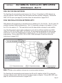
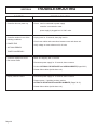
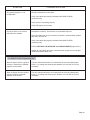
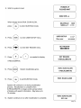
1
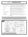
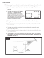
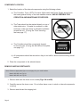
®
Gyro Stabilized Satellite TV Antenna
Model 1500-HD
Model 1800-HD
Installation and Operating Instructions
®
Digital TV Solutions for Mobile Markets
11200 Hampshire Avenue South, Bloomington, MN 55438-2453
Phone: (952) 922-6889
Fax: (952) 922-8424
www.kingcontrols.com
20339 REV G
MEMBER
IMPORTANT!
The satellite TV market is expanding and changing. The information in this manual was accurate at the time
of printing. If your Sea-King does not operate as outlined in this manual please call King Controls at (952)
922-6889 or visit our website at www.kingcontrols.com.
Please read this entire manual before beginning the installation.
DISH NETWORK - Bell TV: If you plan to use the Sea-King with multiple satellite programming and would like
to use the auto-switching feature, your receiver must be configured.
To configure the DISH receiver for automatic satellite switching, the antenna must be on the ground, dock or
motionless platform with no movement (see pages 25-27).
DIRECTV: This antenna will receive available HDTV programming from DIRECTV Ku band satellites at 101°,
110° and 119° with a properly installed HD converter accessory #9747 (included). It will not receive channels
broadcast from DIRECTV’s Ka band satellites at 99° and 103°.
TABLE OF CONTENTS
Section
Contents
Page
1.
INTRODUCTION............................................................................................................2
2.
DEFINITION OF TERMS ...............................................................................................3
3.
INSTALLATION .........................................................................................................4-17
4.
OPERATION ...........................................................................................................18-21
5.
AUTOMATIC SATELLITE SWITCHING: DIRECTV® ..............................................22-23
6.
AUTOMATIC SATELLITE SWITCHING: DISH NETWORK® - BELL TV .......................25
7.
CHECK SWITCH PROCEDURE ............................................................................26-27
8.
TROUBLESHOOTING............................................................................................28-31
9.
MAINTENANCE ...........................................................................................................32
10.
LIMITED WARRANTY .................................................................................................33
ELECTRICAL HAZARD WARNING!
The coax cable that connects the dome unit to the tuner carries a 24 volt
electrical current. Exercise extreme caution when handling this cable. Do
not cut, break, or splice this line. Do not insert or connect any devices such
as splitters or any other device for any reason. This line is not compatible
with any other equipment. Damage will occur to any device other than the
dome unit if connected to the antenna port on the tuner.
DIRECTV® is a registered trademark of DIRECTV, Inc.
DISH Network® is a registered trademark of DISH Network L.L.C.
Bell ExpressVu and Bell TV are official trademarks of Bell Canada.
DVB is a trademark of the DVB Digital Video Broadcast Project (1991-1996)
King Controls® and Sea-King® are registered trademarks of Electronic Controlled Systems, Inc.
Page 1
SECTION 1
INTRODUCTION
The Sea-King Fully Stabilized Marine Satellite System includes 6 main components (Fig. 1).
Dome (Antenna) Unit
Mounted on the vessel. The dish is covered by a protective dome
that keeps operational components free from the elements.
Controller
Located in the vessel. Used to activate and monitor the system,
and access programming and diagnostic information.
Tuner
Located in the vessel. Decodes the satellite signal so the
Sea-King locks onto and tracks the correct satellite.
HDTV Converter Box
Enables viewing of HDTV signals from DIRECTV 110 satellite.
Multi-switch
Installed for multiple receiver hookup (DIRECTV only).
Power Supply
Located in the vessel. Supplies proper operating voltage to the
Sea-King.
Note: A TV, satellite receiver, and program subscription are also required for satellite TV viewing (sold separately).
You must have an HD Receiver, HDTV Monitor (TV), the proper HD cables (component video or HDMI) and the
appropriate programming subscription in order to view HD programming (sold separately).
Fig. 1
Note: HDTV Converter/Multi-switch installed for DIRECTV HD only.
Overview only: see Installation Section for wiring schematics.
Page 2
SECTION 2
DEFINITION OF TERMS
AZIMUTH: Angle in degrees measured clockwise from Magnetic North (0°) (Fig. 2).
Fig. 2
ELEVATION: Angle in degrees measured from a level plane (Fig. 3).
Fig. 3
SIGNAL STRENGTH: Intensity of electronic signal received from the satellite transmission.
Page 3
SECTION 3
INSTALLATION
TOOLS AND MATERIALS REQUIRED
•
•
•
•
•
•
•
drill and drill bit set
tape measure
7/16” open end wrench (coax connections)
5/32” allen wrench, channel lock or pliers (to remove shipping bolt)
1/8” allen wrench or phillips screw driver (to remove dome cover)
appropriate fasteners and tools to install all components and wiring
adhesive sealant, compatible with vessel material
KIT CONTENTS
1. Unpack and identify all components (Fig. 4).
Fig. 4
Page 4
DOME LOCATION
1. Select an area on the vessel for the dome unit, keeping in mind the coax cables will enter the
vessel through the surface directly beneath the dome unit. Use the following criteria:
a) The shortest distance between the dome unit and the main satellite receiver is most
desirable.
b) The dome unit requires a 16.5” (model
1500-HD) or 20” (model 1800-HD)
diameter mounting area on the vessel
surface. You may also use an industry
standard mount. (Call King Controls or visit
www.kingcontrols.com for more information.)
Exact hole spacing is shown at right.
Distances are to centers of holes.
c) The dome unit should never be mounted so that it is tilted more than two degrees
in any direction.
d) Keep the dome unit as far away from the radar as possible, and if possible above the
level of the radar.
e) The dome unit should be mounted as close as possible to the center of the vessel
(fore-aft and side to side).
f)
The mounting surface must be strong enough not to flex under the weight of the unit or
from vessel vibrations.
g) There must be no “line of sight” obstructions from this location. Items such as masts or
radar antennas that are too close to the dome unit may prevent the satellite signal from
reaching the dish (Fig. 5).
Fig. 5
Page 5
COMPONENT LOCATION
1. Select the location of the internal components using the following criteria:
a) The Controller, Tuner, HDTV Converter, Multi-switch and Power Supply should be in
the same general vicinity of the main satellite receiver, AND ACCESSIBLE FOR
OPERATION AND MAINTENANCE PURPOSES.
b) The Tuner should not be stacked directly on top of
other electronics. If located in a cabinet or other
enclosure, make sure there is adequate ventilation
around the unit. (If using the Tuner mounting
feet see page 17.)
c) The Controller should be conveniently located
for the end user. (If using the Wall Mount Faceplate,
see page 16.)
d) All components should be secured so they do not shift or bounce around during vessel
motion.
2. Place the components in the selected areas.
REMOVE SHIPPING RESTRAINTS
Note: Reference appropriate figure on next page for your model number:
Model 1500-HD: see Fig. 6A
Model 1800-HD: see Fig. 6B
1. Remove and save the dome cover screws (Figs. 6A and 6B).
2. Carefully remove the dome cover. Do not allow dome cover to catch on internal components
or wiring.
3. Remove and discard the shipping bolt.
Page 6
Fig. 6A
1500-HD
IMPORTANT!
The shipping bolt must be
removed prior to installation.
IMPORTANT!
CAREFULLY remove the dome
cover. Do not allow dome
cover to catch on internal
components or wiring.
Fig. 6B
1800-HD
IMPORTANT!
The shipping bolt must be
removed prior to installation.
IMPORTANT!
CAREFULLY remove the dome
cover. Do not allow dome
cover to catch on internal
components or wiring.
Page 7
EXTREMELY IMPORTANT!
NEVER lift the unit by the LNB assembly, Wave Guide assembly, or the dish.
Lift the unit by the base ONLY.
PRE-INSTALLATION CHECK
To verify proper operation of the components, perform a Pre-Installation Check as follows:
1. Place the dome unit in your chosen location and on its mounting pedestal. Temporarily
secure the unit from falling. DO NOT PERMANENTLY MOUNT THE DOME UNIT UNTIL
YOU HAVE COMPLETED THE PRE-INSTALLATION CHECK ON THE NEXT PAGE.
If mounting to the vessel surface, you will need to
temporarily place the dome unit on a pedestal or
blocks to perform the pre-installation check.
IMPORTANT! IF CONFIGURING THE RECEIVER FOR MULTIPLE SATELLITE
SWITCHING WITH DISH NETWORK OR BELL TV, Y0U MUST DO THE
PRE-INSTALLATION CHECK ON A MOTIONLESS PLATFORM SUCH AS THE DOCK
OR GROUND.
ELECTRICAL HAZARD WARNING!
The coax cable that connects the dome unit to the tuner carries a
24 volt electrical current. Exercise extreme caution when handling
this cable. Do not cut, break, or splice this line. Do not insert or
connect any devices such as splitters or any other device for any
reason. This line is not compatible with any other equipment.
Damage will occur to any device other than the dome unit if
connected to the antenna port on the tuner.
Page 8
2. Use Figs.10-11 on pages 13-14 to determine your desired wiring configuration.
TEMPORARILY connect system as outlined.
If using both 50’ coax, label the ends of one coax to avoid confusion when making the
connections.
MAKE SURE TO CONNECT POWER LAST.
3. Verify system operates properly as described in Section 4 OPERATION, Page 18.
DISH NETWORK - BELL TV: If configuring the receiver for multiple satellite switching, do
this now while the antenna unit is on a motionless platform (see page 25).
4. After verifying proper operation of the system, DISCONNECT POWER FIRST then all other
components.
DOME INSTALLATION AND EXTERNAL WIRING
IMPORTANT! USE ONLY THE COAX CABLES SUPPLIED WITH THE SEA-KING.
COIL AND STORE EXCESS CABLE IN THE CABINET WITH THE COMPONENTS.
DO NOT CUT COAX.
If coax cable other than that supplied with the Sea-King is used, the following guidelines must
be followed:
1) Ends must be terminated with SNAP-N-SEAL® connectors (Fig. 7.)
(DO NOT USE TWIST-ON OR HEX-CRIMPED CONNECTORS.)
2) Cable must be RG6 and rated at 2.2 GHz or higher.
Fig. 7
IMPORTANT! Rubber O-rings must be REMOVED from ends of all SNAP-N-SEAL® connectors.
Page 9
IMPORTANT! Make sure power supply is disconnected from 110 volt source before continuing with
permanent installation.
The installer is responsible for weatherproofing all holes in the vessel.
Note: The installer is responsible for determining the most appropriate fastener to secure the dome unit to the
pedestal or vessel surface. Depending on the surface material, fasteners such as lag screws, sheet metal
screws, toggle bolts and T anchors may be used.
1. Determine the path of the coax cable(s) from the dome unit to the internal components. Drill
necessary holes (3/4”) in vessel surface where coax will enter vessel. Route coax cable(s)
leaving enough slack to attach to, and mount, dome unit.
2. Apply foam gasket to bottom of dome unit (Fig. 8).
Fig. 8
Note: The Sea-King is wired for multiple receiver support. There are two coax ports on the bottom of the dome unit.
The one labeled “MAIN” MUST be connected to the Tuner (IDB) in vessel. The unlabeled port can be used for
an additional receiver (see page 13).
IMPORTANT! You must fill the ends of all external coax cables with the supplied dielectric grease.
Failure to do so will void product warranty.
Page 10
3. Fill end of coax cable that will connect to the MAIN port on the antenna unit with supplied
dielectric grease. Connect this end of the coax cable to the MAIN port and tighten
connection (Fig. 9).
If using a second (auxiliary) receiver, fill end of second coax cable and connect it to the
unlabeled port. Tighten connection.
DO NOT OVER TIGHTEN CONNECTIONS.
4. Snap the gel-filled boots around the coax cables, then push flush against the bottom of the
dome unit.
Fig. 9
IMPORTANT!
You must fill the ends of the
external coax cables with the
supplied dielectric grease.
Failure to do so will void
product warranty.
Coax connections
should be snug.
DO NOT OVER TIGHTEN!
Gel-filled boots must sit flush
against bottom of dome unit.
5. Use the four mounting holes inside the base to install the dome unit to the mounting pedestal
or the vessel surface.
6. Secure coax every 12-18 inches and seal all openings where the coax enters the vessel so
they are entirely waterproof (inside and outside of the holes).
IMPORTANT! The dome cover screws have a pre-applied locking compound on them.
DO NOT APPLY ANY ADDITIONAL LOCKING COMPOUND TO THE SCREWS.
APPLYING ADDITIONAL COMPOUND WILL VOID THE WARRANTY AND MAY CAUSE
CRACKING IN THE DOME COVER.
When re-installing the dome cover, CAREFULLY lower it onto the base, tilting it side to side as
necessary to prevent damaging internal components.
7. Replace dome cover on base and align holes in dome cover with holes in base. Attach
dome cover with dome cover screws saved earlier. Tighten ALL screws securely.
DO NOT APPLY ANY LOCKING COMPOUND TO THE SCREWS!
Page 11
ELECTRICAL HAZARD WARNING!
The coax cable that connects the dome unit to the tuner carries a
24 volt electrical current. Exercise extreme caution when handling
this cable. Do not cut, break, or splice this line. Do not insert or
connect any devices such as splitters or any other device for any
reason. This line is not compatible with any other equipment.
Damage will occur to any device other than the dome unit if
connected to the antenna port on the tuner.
INTERNAL WIRING
IMPORTANT! The 50’ coax from the “MAIN” port on the dome unit MUST be connected to the Tuner (IDB) in
the vessel.
Coax connections should be snug. DO NOT OVER TIGHTEN!
CONNECT POWER SUPPLY LAST. When connecting the power supply cable to the tuner, push
in the power supply cable end until it is flush against the back of the tuner.
You must apply a light coating of dielectric grease to the female threads of internal coax
connections and to the center stinger of the male coax connections.
1. Choose your desired wiring configuration:
DISH Network/Bell TV:
DIRECTV
Fig. 10, Page 13
Fig. 11, Page 14
2. Make all connections as shown in the wiring diagrams.
Apply a light coating of dielectric grease to the female threads of internal coax connections
and to the center stinger of the male coax connections.
ALWAYS CONNECT THE POWER SUPPLY LAST.
Note: When the power supply is connected, the controller should turn on for 3 seconds and then turn off. If the
controller stays on, Press the ENTER and “-” buttons simultaneously to turn unit off.
3. Perform a search to verify all connections are correct (see page 18).
Page 12
Fig. 10
DISH Network/Bell TV
Sea-King 1500-HD & 1800-HD
Auto-switching from master receiver only
Note:
In order to view programming from the master and secondary
receivers simultaneously, both receivers must be tuned to a channel
broadcast from the same satellite. Use the controller to manually
switch satellites for the secondary receiver.
Note: HDTV receivers require HDMI or component
video/audio cable connection to TV.
IMPORTANT! AVOID SHARP BENDS WHEN ROUTING COAX.
Page 13
Fig. 11
DIRECTV Installation
Sea-King 1500-HD & 1800-HD
Auto-switching from any receiver
Note:
To automatically switch between satellites
using any receiver, tune all other receivers to
channel 202 on the 101 satellite.
IMPORTANT!
HDTV Converter must be hooked
to 18V input on multi-switch.
Note: HDTV receivers require HDMI or component video/audio cable connection to TV.
IMPORTANT! AVOID SHARP BENDS WHEN ROUTING COAX.
Page 14
This page intentionally left blank.
Page 15
OPTIONAL WALL MOUNT FACEPLATE (INCLUDED)
Note: If not using the faceplate, see faceplate removal instructions below.
IMPORTANT! Depending on the thickness of the vessel wall, a relief notch may need to be cut for the cable.
THE CABLE MUST NOT BE PINCHED OR BENT WHEN MOUNTING THE DISPLAY.
1. Use the Faceplate as a template to mark and cut out the mounting cavity, and if necessary,
mark and drill the mounting holes (Fig. 12).
2. Mount Faceplate in wall with supplied screws.
Fig. 12
Note:
Depending on the mounting
surface, pilot holes for the
screws may or may not need
to be drilled.
The Faceplate is optional and can be removed as follows: (Fig. 13)
1. Remove 4 screws from Controller.
2. Slide Faceplate off of Controller.
3. Replace 4 screws.
Fig. 13
Page 16
TUNER MOUNTING OPTIONS
You can mount the tuner or leave it freestanding:
a) You can mount the tuner to an appropriate surface (Fig. 14).
b) You can leave the tuner freestanding. If space requirements dictate, the mounting feet can
be snapped off.
Fig. 14
Note: The installer is responsible for determining the most appropriate fasteners to secure
the tuner to the chosen surface.
Depending on the mounting surface, pilot holes for the fasteners may or may not
need to be drilled.
Page 17
SECTION 4
OPERATION
IMPORTANT! There must be a clear “line of sight” to the satellite (See Fig. 2, Page 3). Terrain, other
boats, buildings, trees, masts, telephone poles, etc. can all block the satellite signal from
reaching the dish.
Note: This example is for the DTV 101 satellite in Region 2-North Central. The information on your controller will vary
depending on the satellite and region you have chosen (see pages 20-21).
Note: The Sea-King must remain powered on to
maintain a signal. If you are going to be
stationary and wish to continue watching TV,
DO NOT TURN THE SYSTEM OFF.
Page 18
AUTOMATIC SATELLITE SWITCHING
DIRECTV: Before using the automatic switching feature, you must configure the Sea-king and your receiver for your
desired option. For switching options see pages 22-23.
DISH Network - Bell TV: Before using the automatic switching feature, you must configure the Sea-King and your
receiver for your desired option. For switching options see page 25.
Your receiver may have already been configured for automatic satellite switching by the
installer. You can determine this by looking at the Check Switch Installation Summary
screen in your receiver, or call the King Controls Service Department at (952) 922-6889.
1. Simply choose your desired channel using the receiver’s remote control. The Sea-King will
automatically switch to the appropriate satellite.
DIRECTV: If you select an HD channel and the picture does not appear, the channel is
located on an alternate satellite. Press the + button to select the alternate pair of satellites.
See page 23 for details.
DISH Network HD: If you are unable to receive all of your HD programming, you will need to
switch satellite trios. See page 25, DISH 1000/1000a FOR DISH NETWORK HDTV for trio
information, and follow the instructions on page 20.
Note: For better performance when using the automatic satellite switching feature, change channels by selecting your
program from the channel guide rather than channel surfing.
It is common for the picture to pixel or display an error message when the antenna is switching between
satellites, or the signal has been temporarily blocked. PLEASE BE PATIENT. THE PICTURE WILL RETURN.
If an error message appears for an extended period, selecting CANCEL may help clear the message
more quickly.
Page 19
SET SATELLITE SERVICE
IMPORTANT!: If you choose any DISH Network or Bell TV option in steps 1-3 below, you must then run the
check switch on pages 26-27.
All of the satellite options listed may not be available with your unit. If you cannot lock onto
your chosen satellite(s), call the King Controls Service Department.
SATELLITE LIBRARY
DTV 101
DTV 101/ 110 hd
DTV 101/ 119
Sat 110
Sat 119
DISH 61
DISH 129
DISH 148
DISH 110/119
DISH 1000
DISH 1000a
EXPVU 82
EXPVU 91
DISH 72.5
DISH 77.0
BEV 82/91
DIRECTV at 101
DIRECTV HDTV at 101 and 110*
DIRECTV HDTV at 101 and 119
DISH Network at 110
DISH Network at 119
DISH Network at 61.5
DISH Network at 129
DISH Network at 148
DISH Network at 110 and 119 (DISH 500)
DISH Network HDTV at 110, 119, and 129 (DISH HD Western Arc with Locals)
DISH Network HDTV at 61.5, 110, and 119 (DISH HD Alternate with Locals)
Bell TV at 82 (formerly Bell ExpressVu)
Bell TV at 91 (formerly Bell ExpressVu)
DISH Network at 72.5
DISH Network at 77
Bell TV at 82 and 91 (formerly Bell ExpressVu)
*Note: The King Controls HD TV Converter Box (#9747 or #9747-AM) is required
to receive HD programming from the DIRECTV satellite at 110.
Page 20
SET REGION (OPTIONAL)
Note: To reduce satellite acquisition time, you can set your current region.
REGION OPTIONS:
1
2
3
4
5
6
7
8
9
0
NORTH WEST
NORTH CENTRAL
NORTH EAST
CENTRAL WEST
MIDDLE CENTRAL
CENTRAL EAST
SOUTH WEST
SOUTH CENTRAL
SOUTH EAST
ALL REGIONS
RECALIBRATE
Page 21
SECTION 5
AUTOMATIC SATELLITE SWITCHING
DIRECTV
DIRECTV 101 SATELLITE ONLY
To receive programming from the DIRECTV 101 satellite only, choose the DTV 101 option (see page
20).
If you have a newer receiver or current software, choose the following dish configuration settings
thru the receiver’s satellite set-up menu screens:
Dish Type: 01: 18” Round
Switch Type: 02:Multiswitch
If you have an older receiver, choose round dish-1 satellite.
101/119 AUTOMATIC SATELLITE SWITCHING
To automatically switch between the 101 and 119 satellites for DIRECTV, choose the DTV 101/119
option (see page 20).
If you have a newer receiver or current software, choose the following dish configuration settings
thru the receiver’s satellite set-up menu screens:
Dish Type: 02: 3-LNB (18 x 20”)
Switch Type: 02:Multiswitch
If you have an older receiver, choose oval dish-2 satellites.
HD PROGRAMMING FROM THE 110 SATELLITE
IMPORTANT! This King-Dome will receive available HDTV programming from DIRECTV Ku band satellites at
101°, 110° and 119° with the properly installed HD converter accessory. It will not receive
channels broadcast from DIRECTV’s Ka band satellites at 99° and 103°.
With the properly installed HDTV Converter and multi-switch (included), this Sea-King will allow you
to receive the specially formatted HD signals from DIRECTV’s 110 satellite and automatically switch
between satellites 101/110 or 101/119 when simply changing channels (see the next page for
instructions). Set your receiver the same as you would for 101/119.
Note: Any receiver can control the antenna switching if the last channel selected on all other receivers was on an odd
transponder on the 101 satellite such as channel 202. (At the time of publication, channel 202 is broadcast on
an odd transponder on satellite 101. This is subject to change. If in doubt whether channel 202 is still on an
odd transponder, contact DIRECTV or call King Controls.)
The antenna can only receive programming from one satellite at a time. If you change channels on your main
receiver, and the antenna has to change satellites, you may lose programming on other receivers.
You can selectively disable automatic satellite switching on individual receivers with the use of one or more tone
block accessories. Please contact King Controls for configuration options.
Manual Switching: To disable automatic switching, manually select your desired satellite using the controller as
shown on page 20.
Page 22
SEA-KING CONFIGURATION: HD PROGRAMMING FROM THE 110 SATELLITE
IMPORTANT! Select your current region first. Failure to select your current region may result in
extraordinary delays in channel acquisition (see page 21).
1. Make sure your current region is selected (see page 21).
2. Select your satellite pair
(see page 20).
Your channels are broadcast from 5 different satellite locations, and the antenna can be set
to automatically switch between two satellites (101/110) or (101/119). If you select the
(101/110) satellite pair on the controller, the antenna will automatically switch to the
appropriate satellite when a channel broadcast from the 101 or 110 satellite is selected. In
this example, if you select a channel that is broadcast from the 119 satellite, you will need to
select the (101/119) satellite pair on the controller and then the antenna will automatically
switch to the appropriate satellite when a channel broadcast from the 101 or 119 satellite is
selected.
3. To change the selected satellite pair, simply press the
+
button on the controller.
Note: The program guide will show all channels available from the 101, 110, 119 satellites, however it may take up to
an hour for this information to be downloaded into the receiver after the satellite is acquired. If all of your
channels do not load in the guide within an hour, press the reset button on the front of your DIRECTV receiver.
When switching between satellites, the TV picture may be disrupted for a brief period while the receiver
processes the signal from the satellite.
Page 23
This page intentionally left blank.
Page 24
SECTION 6
AUTOMATIC SATELLITE SWITCHING
DISH Network - Bell TV
DISH 500 FOR DISH NETWORK
The Sea-King will automatically switch between the 110 and 119 satellites for DISH Network by
using the receiver’s remote control, after the receiver has been properly configured. Choose the
DISH 110/119 option (see page 20) and then follow the instructions on pages 26-27.
DISH 1000/1000a FOR DISH NETWORK HDTV
DISH Network HD programming is broadcast from 4 satellites (61.5,110,119,129). The 61.5 and 129
satellites broadcast identical programming. The 61.5 is generally stronger in the eastern U.S. and
the 129 in the western U.S. The map below shows the approximate coverage for each satellite.
Your Sea-King antenna can be easily configured to work with two different satellite trios (DISH
1000a: 61.5,110,119 or DISH 1000: 110,119,129). By choosing the appropriate trio that includes
either the 61.5 or the 129 satellite based on where you are, you can receive all of your desired
programming. Choose either DISH 1000 or DISH 1000a (see page 20) and then follow the
instructions on pages 26-27.
Note: This map is an
approximation only. Which trio
works best in a given location
may differ from what is indicated
on the map.
BELL TV
(May not be available in all areas due to service provider limitations.)
The Sea-King will automatically switch between the 82 and 91 satellites for Bell TV by using the
receiver’s remote control, after the receiver has been properly configured. Choose BEV 82/91 (see
page 20) and follow the instructions on pages 26-27.
Page 25
SECTION 7
CHECK SWITCH PROCEDURE
DISH Network - Bell TV
IMPORTANT! The antenna must be on the ground, dock or motionless platform with no movement in order to
configure the DISH HD receiver.
If you are an end user and the Sea-King is already permanently mounted, you can perform the
configuration if the vessel is tied up tightly with no movement.
For automatic satellite switching, King Controls recommends using a DISH Network model 311
receiver for DISH 500, and a DISH Network model ViP211 or a ViP211k HDTV receiver for DISH
1000/1000a. Do not use dual tuner receivers or recorders.
If you do not have a clear view of the satellites, the switch will not load.
Note: The SW21 and SW64 switches are a receiver software configuration that is loaded into the receiver after
running a check switch test with the dish locked on and configured for the appropriate service.
This one time procedure will not need to be repeated after successful installation, unless a) check switch test is
run again while connected to a home dish system, b) check switch is run when a receiver is not connected, or c)
you travel outside the coverage area of the pre-set satellite trio (DISH 1000/1000a only).
1. Make sure the Sea-King has locked onto the satellite(s) from the selection you made on page
20 by verifying the satellite option in the controller’s display window.
2. On the receiver remote, press menu, 6, 1, 1.
3. Highlight Check Switch and press Select.
Note: Some receivers may prompt you to select
check switch a second time to initiate the test.
4. Make sure Superdish and Alternate boxes
are NOT selected.
Note: Not all receivers will display a screen with
options that include superdish and alternate boxes.
5. Highlight Test and press Select.
Screen graphics may vary.
The unit will perform a check switch test, and the dish will periodically move back and forth.
(This process will take several minutes.)
Page 26
6. When test is complete, a screen similar to
one of the following should appear:
(Screen graphics may vary.)
ALL SINGLE SATELLITES
NO SWITCH DETECTED
or
INSTALLED DEVICE
UNKNOWN
DISH 500
BELL TV 82/91
MUST SHOW
“SW21”
NO “X”s
DISH 1000
DISH 1000a
NO “X”s
MUST SHOW
“SW64”
If indicated results are not obtained, go back to Step 1 and run test again. Contact King
Controls if the check switch fails to load after 4 attempts.
7. Save the settings, exit to the main menu screen and wait for your programming to download.
8. DISH 1000/1000a ONLY: Verify your saved settings show your desired satellite trio
(110, 119, 129 or 110, 119, 61.5).
Check switch is complete.
Page 27
SECTION 8
SYMPTOM
Controller does not power up.
TROUBLESHOOTING
POSSIBLE SOLUTION
Check: tuner is connected to power supply.
controller is connected to tuner.
power supply is plugged into 110 VAC outlet.
Controller remains in one of the
following conditions:
Unplug tuner for 10 seconds, then plug back in.
Check coax cables and connections between tuner and dome unit.
POWER TRIP
Verify voltage on coax at dome unit is 24 volts.
ANT COM ERROR?
TUNER COM ERROR?
Controller displays AZ FAULT.
Dish cannot rotate
Make sure shipping bolt is removed.
Disconnect power supply for 15 seconds, then reconnect.
Perform OPTION 21 RE-INITIALIZE and 0-RECALIBRATE (Pages 30-31).
Reseat ribbon cables (inside dome unit).
Display reads EL FAULT.
Disconnect power supply for 15 seconds, then reconnect.
Restart system. If problem persists, perform
OPTION 21 RE-INITIALIZE and 0-RECALIBRATE (Pages 30-31).
Reseat ribbon cables (inside dome unit).
Page 28
SYMPTOM
Only getting signal on 1/2 of
transponders.
POSSIBLE SOLUTION
Kinked or sharply bent coax cable.
Verify coax cables are properly terminated with SNAP-N-SEAL®
connectors only.
Verify receiver is operating properly.
Verify LNB type is set correctly.
Unit never locks on or locks on
and drifts off of satellite.
Atmospheric moisture. Unit will lock on as weather improves.
Check for obstruction in sky in direction of satellite. Select another satellite
and verify unit locks on.
Verify coax cables are properly terminated with SNAP-N-SEAL®
connectors only.
Perform OPTION 21 RE-INITIALIZE and 0-RECALIBRATE (Pages 30-31).
Inspect all coax cables and verify connections are snug but not overly tight
(inside and outside dome unit).
For DIRECTV HDTV Programming only:
When a channel from the guide is
selected, “Searching for Satellite”
appears on the screen.
The new channel selected is not found within the currently selected pair.
Press (+) to change the switching pair between 101/110 and 101/119 as
necessary.
When a channel from the guide is
selected, a different program
appears on the screen.
The new channel selected is not found within the currently selected pair.
Press (+) to change the switching pair between 101/110 and 101/119 as
necessary.
Page 29
OPTION 21 RE-INITIALIZE and 0-RECALIBRATE
Page 30
Page 31
SECTION 9
MAINTENANCE
The Sea-King Satellite System has been designed to be maintenance and trouble free.
For optimum signal strength, keep the dome clean from dirt, bugs, and other debris. Periodic
washing of the dome with mild soap and water is recommended.
IMPORTANT! Do not power wash the Sea-King.
If you plan on storing your vessel for long periods of time, it is recommended that the system be put
through a search procedure on a quarterly basis to keep all moving parts in good working order.
If you have any comments or questions, please contact the King Controls Service Department at
(952) 922-6889, or email King Controls at [email protected].
Rain Fade
Rain or dew on the dome can cause signal interference and make the digital picture freeze, pixel or
go out altogether. This loss of signal is commonly referred to as “rain fade” and is caused by the
combination of water in the atmosphere and water on the dome surface.
To minimize this issue and eliminate the effects of water on the dome, apply King Controls
Dome Magic rain fade solution to the dome. This will prevent water from sticking to the dome
surface and blocking the signal. For additional details on Dome Magic rain fade solution please
contact your authorized Sea-King dealer or call King Controls at (952) 922-6889.
®
®
Single Application Packet #1830-SP
Page 32
Spray Can #1830
SECTION 10
LIMITED WARRANTY
Every new King Controls Satellite System is thoroughly inspected and tested before leaving the factory, and is covered by the
following two year parts and one year labor limited warranty from the date of original purchase:
• Two year parts warranty: The customer is not responsible for the cost of replacement parts if the original part is determined to
be defective under the terms of the warranty. The customer is responsible for the cost of replacement parts after two years.
• One year labor warranty: The customer is not responsible for labor costs to repair unit if unit falls under the terms of the
warranty. Any warranty labor outside of that performed at the factory is not covered unless the product has been installed by
an authorized dealer/installer or OEM manufacturer. The customer is responsible for all labor costs after one year.
Should any trouble develop during the warranty period, contact King Controls. You must contact King Controls before the warranty
period expires. The customer must supply proof of purchase (such as a dated sales receipt) when requesting warranty service. If
customer cannot supply proof of purchase, warranty period shall start 30 days after date of manufacture.
Only King Controls and certified dealers are authorized to perform warranty evaluations and repairs. Depending upon the problem,
King Controls may authorize the dealer to perform the necessary repairs, or may have the unit returned to King Controls for repairs.
A certified dealer must not perform any repair without first contacting King Controls for a Service Order Number. King Controls will
advise the dealer on how to proceed with any repairs.
If it is determined that the unit needs to be returned to King Controls, customer must return COMPLETE product, freight prepaid, to:
King Controls, 11200 Hampshire Avenue South, Bloomington, MN 55438-2453.
If inspection shows the trouble is caused by defective workmanship or material, King Controls will repair (or at its option, replace)
without charge.
When returning product, King Controls will supply an RMA number (Return Merchandise Authorization). This number must be clearly
written on the box. Failure to clearly write RMA number on box may result in delays in processing claim. Along with product,
customer should include in the box: his/her name, address, daytime phone number, proof of purchase and description of the problem.
This warranty does not cover installation and external wiring, or remanufactured units. This warranty is not transferable from the
original owner.
Due to the expanding and changing TV market, King Controls cannot be held responsible for changes made to satellite services.
Software updates to address such issues are not covered under warranty.
This warranty also does not apply where:
• The product has been abused, misused, improperly installed or improperly maintained.
• Repairs have been made or attempted by others that are not certified by King Controls to do such repairs.
• Repairs are required because of normal wear and tear.
• Alterations have been made to the product.
• The dome cover has been removed without authorization.
• Supplied grease not used in the external coax connections as specified in the instructions.
• Damage has been caused by power washing.
• Circumstances beyond the control of King Controls cause the product to no longer operate correctly.
• Customer is not the original owner.
In no event shall King Controls be liable for any indirect, incidental, or consequential damages from the sale or use of the
product. This disclaimer applies both during and after the term of the warranty.
King Controls disclaims liability for any implied warranties, including implied warranties of “merchantability” and “fitness
for a specific purpose,” after the one year term of this warranty.
This warranty gives you specific legal rights, and you may also have other rights, which vary from state to state. Some states do not
allow the exclusion or limitation of incidental or consequential damages, so the above limitation or exclusion may not apply to you.
Some states do not allow limitations on how long an implied warranty lasts, so the above limitation may not apply to you.
Page 33
Notes:
Page 34
Notes:
Page 35
Notes:
Page 36
®
11200 Hampshire Avenue South, Bloomington, MN 55438-2453
Phone: (952) 922-6889
Fax: (952) 922-8424
www.kingcontrols.com