1
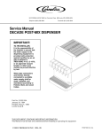
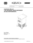
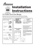
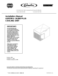
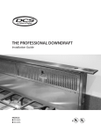
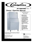
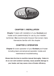
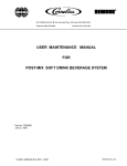
FCB POST-MIX DISPENSER WITH V4 FEATURES (R-404A REFRIGERANT) Operator’s Manual Part No 312030002 May 8, 1996 Control Code A THIS DOCUMENT CONTAINS IMPORTANT INFORMATION This Manual must be read and understood before installing or operating this equipment IMI CORNELIUS INC; 1996 PRINTED IN U.S.A TABLE OF CONTENTS Page SAFETY INFORMATION . . . . . . . . . . . . . . . . . . . . . . . . . . . . . . . . . . . . . . . . . . . . . . . . . . . 1 RECOGNIZE SAFETY INFORMATION . . . . . . . . . . . . . . . . . . . . . . . . . . . . . . . 1 UNDERSTAND SIGNAL WORDS . . . . . . . . . . . . . . . . . . . . . . . . . . . . . . . . . . . 1 FOLLOW SAFETY INSTRUCTIONS . . . . . . . . . . . . . . . . . . . . . . . . . . . . . . . . . 1 CO2 (CARBON DIOXIDE) WARNING . . . . . . . . . . . . . . . . . . . . . . . . . . . . . . . . 1 SHIPPING, STORING, OR RELOCATING UNIT . . . . . . . . . . . . . . . . . . . . . . . 1 OPERATOR’S INSTRUCTIONS . . . . . . . . . . . . . . . . . . . . . . . . . . . . . . . . . . . . . . . . . . . . . 3 CONTROL PANEL (KEYPAD) SECURITY . . . . . . . . . . . . . . . . . . . . . . . . . . . . . . . . 3 CONTROL PANEL SWITCHES . . . . . . . . . . . . . . . . . . . . . . . . . . . . . . . . . . . . . . . . . . 3 ‘‘SYRUP PRIME’’ SWITCHES. . . . . . . . . . . . . . . . . . . . . . . . . . . . . . . . . . . . . . . 4 ‘‘BLEND ON/OFF’’ SWITCHES. . . . . . . . . . . . . . . . . . . . . . . . . . . . . . . . . . . . . . 4 ‘‘MOTOR’’ SWITCHES. . . . . . . . . . . . . . . . . . . . . . . . . . . . . . . . . . . . . . . . . . . . . . 4 ’’ON’’ SWITCHES. . . . . . . . . . . . . . . . . . . . . . . . . . . . . . . . . . . . . . . . . . . . . . . . . . 4 ‘‘OFF’’ SWITCHES. . . . . . . . . . . . . . . . . . . . . . . . . . . . . . . . . . . . . . . . . . . . . . . . . 4 ‘‘ERROR RESET’’ SWITCH. . . . . . . . . . . . . . . . . . . . . . . . . . . . . . . . . . . . . . . . . 4 CONTROL PANEL DISPLAY MESSAGES . . . . . . . . . . . . . . . . . . . . . . . . . . . . . . . . 6 ‘‘FILL 1’’ AND ‘‘FILL 2’’ FAULT MESSAGES. . . . . . . . . . . . . . . . . . . . . . . . . . . 6 ‘‘ERROR 1’’ AND ‘‘ERROR 2’’ FAULT MESSAGES. . . . . . . . . . . . . . . . . . . . . 6 ‘‘OFF 1’’ AND ‘‘OFF 2’’ FAULT MESSAGES. . . . . . . . . . . . . . . . . . . . . . . . . . . 6 ‘‘H2O OUT’’ FAULT MESSAGE. . . . . . . . . . . . . . . . . . . . . . . . . . . . . . . . . . . . . . 6 ‘‘CO2 OUT’’ FAULT MESSAGE. . . . . . . . . . . . . . . . . . . . . . . . . . . . . . . . . . . . . . 6 ‘‘SYRUP 1’’ OR ‘‘SYRUP 2’’ FAULT MESSAGES. . . . . . . . . . . . . . . . . . . . . . . 6 ‘‘DEFROST 1’’ OR ‘‘DEFROST 2’’ DISPLAY MESSAGES. . . . . . . . . . . . . . . 6 ‘‘POINT OF SALE’’ DISPLAY MESSAGES. . . . . . . . . . . . . . . . . . . . . . . . . . . . 6 DEFROST SYSTEMS . . . . . . . . . . . . . . . . . . . . . . . . . . . . . . . . . . . . . . . . . . . . . . . . . . 7 UNITS EQUIPPED WITH HOT-GAS DEFROST SYSTEMS . . . . . . . . . . . . . 7 UNITS EQUIPPED WITH ELECTRIC DEFROST SYSTEMS . . . . . . . . . . . . 7 ‘‘SLEEP’’ (SLEEP TIME) . . . . . . . . . . . . . . . . . . . . . . . . . . . . . . . . . . . . . . . . . . . . . . . . 8 UNITS EQUIPPED WITH HOT-GAS DEFROST SYSTEMS . . . . . . . . . . . . . 8 UNITS EQUIPPED WITH ELECTRIC DEFROST SYSTEMS . . . . . . . . . . . . 8 ‘‘WAKE UP’’ (WAKE UP TIME) . . . . . . . . . . . . . . . . . . . . . . . . . . . . . . . . . . . . . . . . . . 8 FACEPLATE RELIEF VALVES . . . . . . . . . . . . . . . . . . . . . . . . . . . . . . . . . . . . . . . . . . . 8 DISPENSING VALVES . . . . . . . . . . . . . . . . . . . . . . . . . . . . . . . . . . . . . . . . . . . . . . . . . 8 DISPENSED PRODUCT CONDITIONS . . . . . . . . . . . . . . . . . . . . . . . . . . . . . . . . . . . . . . . 9 ‘‘OVERRUN’’, AS APPLIED TO FROZEN CARBONATED BEVERAGES . . . . . . 9 OPERATING CHARACTERISTICS . . . . . . . . . . . . . . . . . . . . . . . . . . . . . . . . . . . . . . 10 OPERATING UNIT . . . . . . . . . . . . . . . . . . . . . . . . . . . . . . . . . . . . . . . . . . . . . . . . . . . . . 10 ADJUSTING CO2 REGULATORS . . . . . . . . . . . . . . . . . . . . . . . . . . . . . . . . . . . . . . . 10 PRIMARY CO2 REGULATOR . . . . . . . . . . . . . . . . . . . . . . . . . . . . . . . . . . . . . . . 10 SECONDARY CO2 REGULATORS . . . . . . . . . . . . . . . . . . . . . . . . . . . . . . . . . . 11 ADJUSTING BRIX (WATER-TO-SYRUP “RATIO”) OF DISPENSED PRODUCT 11 REPLENISHING SYRUP SUPPLY . . . . . . . . . . . . . . . . . . . . . . . . . . . . . . . . . . . . . . . 11 SYRUP TANKS SYSTEM . . . . . . . . . . . . . . . . . . . . . . . . . . . . . . . . . . . . . . . . . . . 11 i 312030002 TABLE OF CONTENTS (cont’d) Page BAG–IN–BOX SYSTEM . . . . . . . . . . . . . . . . . . . . . . . . . . . . . . . . . . . . . . . . . . . . 12 SYRUP FLAVOR CHANGE . . . . . . . . . . . . . . . . . . . . . . . . . . . . . . . . . . . . . . . . . . . . . 12 REPLENISHING CO2 SUPPLY . . . . . . . . . . . . . . . . . . . . . . . . . . . . . . . . . . . . . . . . . . 12 CLEANING AND SANITIZING . . . . . . . . . . . . . . . . . . . . . . . . . . . . . . . . . . . . . . . . . . . 13 DAILY CLEANING OF UNIT . . . . . . . . . . . . . . . . . . . . . . . . . . . . . . . . . . . . . . . . 13 SANITIZING SYRUP SYSTEMS . . . . . . . . . . . . . . . . . . . . . . . . . . . . . . . . . . . . 13 CLEANING CONDENSER COIL . . . . . . . . . . . . . . . . . . . . . . . . . . . . . . . . . . . . . . . . . 16 UNIT WITH AIR-COOLED REFRIGERATION SYSTEM . . . . . . . . . . . . . . . . 16 UNIT WITH REMOTE CONDENSING REFRIGERATION . . . . . . . . . . . . . . . 16 TROUBLESHOOTING . . . . . . . . . . . . . . . . . . . . . . . . . . . . . . . . . . . . . . . . . . . . . . . . . . . . . 17 TROUBLESHOOTING CONTROL PANEL SWITCHES AND FAULT MESSAGES . . . . . . . . . . . . . . . . . . . . . . . . . . . . . . . . . . . . . . . . . . . . . . . . . . . . . . . . . . 17 ONE OR MORE CONTROL PANEL SWITCHES NOT OPERATING. . . . . . 17 ALL CONTROL PANEL SWITCHES NOT OPERATING. . . . . . . . . . . . . . . . . 17 PARTIAL MESSAGE OR DULL (POORLY ILLUMINATED) DISPLAY. . . . . . 17 ONE OR MORE FAULT MESSAGES NOT OPERATING. . . . . . . . . . . . . . . . 17 ALL FAULT MESSAGES NOT OPERATING. . . . . . . . . . . . . . . . . . . . . . . . . . . 17 ‘‘CO2 OUT’’ FAULT MESSAGE GOES ON DURING OPERATION. . . . . . . 18 ‘‘H2O OUT’’ FAULT MESSAGE GOES ON DURING OPERATION. . . . . . . 18 ‘‘SYRUP 1’’ OR ‘‘SYRUP 2’’ FAULT MESSAGE GOES ON DURING OPERATION. . . . . . . . . . . . . . . . . . . . . . . . . . . . . . . . . . . . . . . . . . . . . . . . . . . . . 18 ‘‘ERROR 1’’ OR ‘‘ERROR 2’’ FAULT MESSAGE GOES ON DURING OPERATION. . . . . . . . . . . . . . . . . . . . . . . . . . . . . . . . . . . . . . . . . . . . . . . . . . . . . . 18 FREEZE CYLINDER AUTOMATIC DEFROST CYCLE DOES NOT OPERATE. . . . . . . . . . . . . . . . . . . . . . . . . . . . . . . . . . . . . . . . . . . . . . . . . . . . . . . . 18 UNIT DOES NOT GO OFF AUTOMATIC DEFROST CYCLE. . . . . . . . . . . . 18 MANUAL DEFROST CYCLE DOES NOT OPERATE WHEN ‘‘DEFROST’’ SWITCH IS PRESSED. . . . . . . . . . . . . . . . . . . . . . . . . . . . . . . . . . . . . . . . . . . . . 18 DEFROST CYCLE DOES NOT CANCEL AFTER PRESSING ‘‘CANCEL DEFROST ’’ SWITCH. . . . . . . . . . . . . . . . . . . . . . . . . . . . . . . . . . . . . . . . . . . . . . 18 TROUBLESHOOTING PRODUCT BLENDER TANKS AND CARBONATORS . 18 CARBONATOR WATER PUMP MOTOR WILL NOT OPERATE. . . . . . . . . . 18 CARBONATOR WATER PUMP WILL NOT SHUT OFF. . . . . . . . . . . . . . . . . 19 ERRATIC CARBONATOR WATER PUMP CYCLING. . . . . . . . . . . . . . . . . . . 19 TROUBLESHOOTING DISPENSED PRODUCT . . . . . . . . . . . . . . . . . . . . . . . . . . . 19 BRIX (WATER-TO-SYRUP) ‘‘RATIO’’ OF DISPENSED PRODUCT TOO LOW. . . . . . . . . . . . . . . . . . . . . . . . . . . . . . . . . . . . . . . . . . . . . . . . . . . . . . . . . . . . . 19 BRIX (WATER-TO-SYRUP) ‘‘RATIO’’ OF DISPENSED PRODUCT TOO HIGH. . . . . . . . . . . . . . . . . . . . . . . . . . . . . . . . . . . . . . . . . . . . . . . . . . . . . . . . . . . . . 19 IMPROPER PRODUCT DISPENSED. . . . . . . . . . . . . . . . . . . . . . . . . . . . . . . . . 19 PRODUCT WILL NOT DISPENSE OUT OF DISPENSING VALVE, IN ONLY SMALL AMOUNTS, OR ONLY LIQUID. . . . . . . . . . . . . . . . . . . . . . . . . . . . . . . 19 312030002 FREEZE CYLINDER DOES NOT REFILL AT ALL TIMES WHEN DISPENSING. . . . . . . . . . . . . . . . . . . . . . . . . . . . . . . . . . . . . . . . . . . . . . . . . . . . . 19 FROZEN PRODUCT CONSISTENCY VARIES EXCESSIVELY. . . . . . . . . . 19 ii TABLE OF CONTENTS (cont’d) Page CYLINDER FREEZE-UP. . . . . . . . . . . . . . . . . . . . . . . . . . . . . . . . . . . . . . . . . . . . 20 WARRANTY . . . . . . . . . . . . . . . . . . . . . . . . . . . . . . . . . . . . . . . . . . . . . . . . . . . . . . . . . . . . . . 21 LIST OF FIGURES FIGURE 1. FCB POST-MIX DISPENSERS WITH V4 FEATURES . . . . . . . . . . . . 3 FIGURE 2. CONTROL PANEL SWITCH IDENTIFICATION . . . . . . . . . . . . . . . . . . 4 FIGURE 3. OPERATING CONTROLS (FOUR-FLAVOR UNIT SHOWN) . . . . . . 5 iii 312030002 THIS PAGE LEFT BLANK INTENTIONALLY 312030002 iv SAFETY INFORMATION Recognize Safety Information This is the safety-alert symbol. When you see this symbol on our machine or in this manual, be alert to the potentially of personal injury. Follow recommended precautions and safe operating practices. Understand Signal Words A signal word - DANGER, WARNING, OR CAUTION is used with the safety-alert symbol. DANGER identifies the most serious hazards. Safety signs with signal word DANGER or WARNING are typically near specific hazards. General precautions are listed on CAUTION safety signs. CAUTION also calls attention to safety messages in this manual. DANGER WARNING CAUTION Follow Safety Instructions Carefully read all safety messages in this manual and on your machine safety signs. Keep safety signs in good condition. Replace missing or damaged safety signs. Learn how to operate the machine and how to use the controls properly. Do not let anyone operate the machine without instructions. Keep your machine in proper working condition. Unauthorized modifications to the machine may impair function and/or safety and affect the machine life. CO2 (Carbon Dioxide) Warning CO2 Displaces Oxygen. Strict Attention must be observed in the prevention of CO2 (carbon dioxide) gas leaks in the entire CO2 and soft drink system. If a CO2 gas leak is suspected, particularly in a small area, immediately ventilate the contaminated area before attempting to repair the leak. Personnel exposed to high concentration of CO2 gas will experience tremors which are followed rapidly by loss of consciousness and suffocation. Shipping, Storing, Or Relocating Unit CAUTION: Before shipping, storing, or relocating the Unit, syrup systems must be sanitized and all sanitizing solution must be purged from the syrup systems. All water must also be purged from the plain and carbonated water systems. A freezing ambient environment will cause residual sanitizing solution or water remaining inside the Unit to freeze resulting in damage to the internal components. 1 312030002 THIS PAGE LEFT BLANK INTENTIONALLY 312030002 2 OPERATOR’S INSTRUCTIONS This section describes operating controls and indicators, dispensed product conditions, operating characteristics, Unit operation, replenishing syrup supply, product flavor change, checking CO2 supply, operators daily cleaning of Unit, and sanitizing requirements. SOUND BAFFLE/DRIP TRAY ASS’Y PROVIDED ONLY WITH 3 H.P. UNIT. TWO-FLAVOR DISPENSER OVERCOUNTER DISPENSER FOUR-FLAVOR DISPENSER FIGURE 1. FCB POST-MIX DISPENSERS WITH V4 FEATURES WARNING: Disconnect electrical power to the Unit to prevent personal injury before attempting any internal maintenance. Only qualified personnel should service internal components or electrical wiring. CONTROL PANEL (KEYPAD) SECURITY The optional control panel (keypad) security (options DIP6 switch) may be programmed into the Unit to enable (activate) or disable (de-activate) the control panel security. When the control panel security is enabled, any control panel switch can be pushed and held for 5-seconds to override the control panel security. An audible beep will be heard when the switch is first pushed, then another beep will be heard when the security override has taken place and the switch may be released. Control panel security will be re-established 90-seconds after switch pushing activity has ceased. Control panel (keypad) security should be programmed into the Unit electronics by a qualified Service Person. Note: When in programming menu, the control panel security will not re-establish until after exiting programming menu. CONTROL PANEL SWITCHES (see Figure 2) NOTE: Two-flavor Unit- The No. 1 freeze cylinder is the left-hand cylinder facing the front of the Unit. No. 2 freeze cylinder is to the right of the No. 1 freeze cylinder. Four-flavor Unit- The No. 1 freeze cylinder is the left-hand cylinder facing the front of the Unit. The other three freeze cylinders, to the right of the No.1 freeze cylinder, are labeled 2, 11, and 22. 3 312030002 BLEND ON/OFF ON ÍÍÍÍ ÍÍÍÍ ERROR SYRUP PRIME RESET ER MOTOR Display OFF Side 1 Side 2 <(Backward) (Forward)> Cancel Defrost MS Manual Defrost Menu/Select FIGURE 2. CONTROL PANEL SWITCH IDENTIFICATION ‘‘SYRUP PRIME’’ Switches. The ‘‘SYRUP PRIME’’ switches, located on the control panel, are touch-type switches and require only pressing to activate. The ‘‘SYRUP PRIME’’ switches are used only when filling the syrup systems sold-out floats during syrup replenishing, syrup flavor changeover, or sanitizing the syrup systems. ‘‘BLEND ON/OFF’’ Switches. The ‘‘BLEND ON/OFF” switches, located on the control panel, are touch-type switches and require only pressing to activate. These switches are used to fill the product blender tanks after the sold-out floats have been filled using the ‘‘SYRUP PRIME’’ switches. After the product blender tanks have been filled, the “BLEND ON/OFF” switches may be pressed again to prevent more product from entering the product blender tanks during BRIX test. The “ON” and “BLEND ON/OFF” switches must be pressed to operate the freeze cylinders beaters and refrigeration system during normal operation. ‘‘MOTOR’’ Switches. The ‘‘MOTOR’’ switches, located on the control panel, are touch-type switches and require only pressing to activate. These switches are used to operate the freeze cylinders beaters with no refrigeration during sanitizing. ’’ON’’ Switches. The ‘‘ON’’ switches, located on the control panel, are touch-type switches and require only pressing to activate. These switches are used to operate the freeze cylinders beaters and refrigeration system after cylinders have been filled with product. The freeze cylinders beaters and refrigeration system may be stopped by pressing the ‘‘OFF’’ switches. ‘‘OFF’’ Switches. The ‘‘OFF’’ switches, located on the control panel, are touch-type switches and require only pressing to activate. These switches are used to stop freeze cylinders beaters and refrigeration system. ‘‘ERROR RESET’’ Switch. ‘‘ERROR RESET’’ switch, located on the control panel, is a touch-type switch and requires only pressing to activate. The ‘‘ERROR RESET’’ switch is used to restore normal operation after error within Unit (indicated by ‘‘ERROR 1’’ or ‘‘ERROR 2’’ on message display) has been corrected. 312030002 4 TOP PANEL CONTROL PANEL (2) (SEE FIGURE 2) FACEPLATE RELIEF VALVE (4) BACK PANEL CUP REST FACEPLATE (4) DRIP TRAY DISPENSING VALVE (4) SIDE PANEL (2) CONDENSER COIL ACCESS PANEL VENTILATION LOUVERS NOTE: Two-flavor Unit- The No. 1 freeze cylinder is the left-hand cylinder facing the front of the Unit. No. 2 freeze cylinder is to the right of No. 1 freeze cylinder. Four-flavor Unit- The No. 1 freeze cylinder is the left-hand cylinder facing the front of the Unit. The other three freeze cylinders, to the right of No. 1 freeze cylinder, are labeled 2, 11, and 22. FIGURE 3. OPERATING CONTROLS (FOUR-FLAVOR UNIT SHOWN) 5 312030002 CONTROL PANEL DISPLAY MESSAGES ‘‘FILL 1’’ and ‘‘FILL 2’’ Fault Messages. ‘‘FILL 1’’ and ‘‘FILL 2’’ fault messages will appear on the message display only after the “SYRUP PRIME” switches have been pressed and the syrup systems sold-out floats have been filled with product. ‘‘FILL 1’’ and ‘‘FILL 2’’ fault messages will continue to be displayed until the “BLEND ON/OFF” switches have been pressed to fill the product blender tanks with product. ‘‘ERROR 1’’ and ‘‘ERROR 2’’ Fault Messages. ‘‘ERROR 1’’ and ‘‘ERROR 2’’ fault messages will appear on the message display only if an error within the Unit has developed interrupting normal operation. Error will have to be located and corrected, then press the ‘‘ERROR RESET’’ to restore the Unit to normal operation. ‘‘ERROR 1’’ or ‘‘ERROR 2’’ fault message will disappear from the display. ‘‘OFF 1’’ and ‘‘OFF 2’’ Fault Messages. ‘‘OFF 1’’ and ‘‘OFF 2’’ fault messages will appear on the message display when either freeze cylinder beater is not operating. ‘‘H2O OUT’’ Fault Message. The Unit plain water inlet system contains a water pressure switch. An “H2O OUT” fault message will appear on the message display if the plain water source to the unit has been disrupted or if a water pressure drop should occur. The Unit will continue to operate for 1-1/2 minutes after ‘‘H2O OUT’’ fault message has appeared. If the water pressure has not been restored or the water pressure improved after 1-1/2 minutes, the Unit operation will shut down. After plain water source has been restored or the water pressure has improved, the Unit will resume it’s normal operation and the ‘‘H2O OUT’’ fault message will disappear from the message display. ‘‘CO2 OUT’’ Fault Message. ‘‘CO2 OUT’’ fault message will appear on the message display when CO2 supply to the Unit has been turned off or if the CO2 pressure drops below 50-psi. A minimum CO2 pressure of 75-psi must be available to the Unit to extinguish the ‘‘CO2 OUT’’ fault message. ‘‘SYRUP 1’’ or ‘‘SYRUP 2’’ Fault Messages. ‘‘SYRUP 1’’ or ‘‘SYRUP 2’’ fault messages will appear on the message display if the syrup supply is not connected to the Unit syrup system or if the syrup supply is exhausted. The Unit syrup systems syrup float switches must be filled with syrup to extinguish the ‘‘SYRUP 1’’ or ‘‘SYRUP 2’’ fault messages. ‘‘DEFROST 1’’ or ‘‘DEFROST 2’’ Display Messages. ‘‘DEFROST 1’’ or ‘‘DEFROST 2’’ display messages will appear on the message display if either freeze cylinder is in the defrost mode. ‘‘DEFROST 1’’ or ‘‘DEFROST 2’’ messages will remain on during the defrost cycle and will disappear when the cycle has ended. ‘‘POINT OF SALE’’ Display Messages. Three ‘‘POINT OF SALE‘’ display messages are available to choose from and may be programmed into the Unit to appear on the message display. The “POINT OF SALE” display messages should be programmed into the Unit electronics by a qualified Service Person. 312030002 6 DEFROST SYSTEMS NOTE: The automatic defrost, “SLEEP” (SLEEP TIME), and “WAKE UP” (WAKE UP TIME) should be programmed into the Unit electronics by a qualified Service Person. UNITS EQUIPPED WITH HOT-GAS DEFROST SYSTEMS The Unit is equipped with both manual and automatic hot-gas defrost systems. The automatic defrost system may be programmed into the Unit to occur up to nine different times a day with a minimum of two hours between defrost time settings or the system may be completely turned off. Manual Hot-Gas Defrost System. On the Two-Flavor Unit, the manual hot-gas defrost system may be activated at any time by pressing the ‘‘MANUAL DEFROST’’ switch on front of the Unit. The refrigeration compressor will operate for a short time, then both freeze cylinders will go into defrost and defrost for approximately 60-seconds. On the Four-Flavor Unit, The manual hot-gas defrost system may be activated at any time by pressing the “MANUAL DEFROST” switch on front of the Unit. The refrigeration compressor will operate for a short time, then both No. 1 and No.11 or No. 2 and No. 22 (depending upon which “MANUAL DEFROST” switch was pressed) freeze cylinder only will go into defrost and defrost for 60-seconds. At the end of the manual defrost cycle, the Unit will return to normal operation. The manual defrost may be cancelled at any time by pressing the “CANCEL DEFROST” switch. Automatic Hot-Gas Defrost System. NOTE: The following paragraph describes the Automatic Hot-Gas Defrost system operation for the Two-Flavor FCB Dispenser No. 1 and No. 2 freeze cylinders. This paragraph also describes the Automatic Hot-Gas Defrost system operation for the Four-Flavor FCB Dispenser No. 11 and No. 22 freeze cylinders, which is identical to the No. 1 and No. 2 freeze cylinders. The automatic hot-gas defrost system may be programmed into the Unit to occur up to nine different times a day with a minimum of 2-hours between defrost settings. At the start of each automatic defrost cycle, the refrigeration compressor will operate for 30-seconds to pump freon out of the freeze cylinders evaporator coils. After freon has been pumped out of the freeze cylinders evaporator coils, No. 1 freeze cylinder only will go into defrost cycle and defrost for approximately 7-minutes, then will return to normal operation. This ends the automatic defrost cycle of No. 1 freeze cylinder. No. 2 freeze cylinder will defrost 30-minutes after the start of No. 1 freeze cylinder. The next automatic defrost cycle will occur according to the time programmed into the Unit. The automatic defrost may be cancelled at any time by pressing the ‘‘CANCEL DEFROST’’ switch. UNITS EQUIPPED WITH ELECTRIC DEFROST SYSTEMS The Two-Flavor Overcounter (requiring remote condensing refrigeration) Unit is equipped with both manual and automatic electric defrost systems. The automatic defrost system may be programmed into the Unit to occur up to nine different times a day with a minimum of two hours between defrost time settings or the system may be completely turned off. Manual Electric Defrost System. The manual electric defrost system may be activated at any time by pressing the “DEFROST” switch on front of the Unit. The refrigeration compressor will operate for a short time, then both freeze cylinders will go into defrost and defrost for approximately 15-minutes. At end of the manual electric defrost cycle, the Unit will return to normal operation. The manual electric defrost may be cancelled at any time by pressing the “CANCEL DEFROST” switch. 7 312030002 Automatic Electric Defrost System. The automatic electric defrost system may be programmed into the Unit to occur up to nine different times a day with a minimum of two hours between defrost settings. At start of each automatic electric defrost cycle, the refrigeration compressor will operate for a short time. No.1 freeze cylinder only will go into defrost cycle and defrost for approximately 15-minutes, then the Unit will return to normal operation. This ends the automatic defrost cycle of No.1 freeze cylinder. No. 2 freeze cylinder will defrost 30-minutes after the start of No. 1 freeze cylinder. The next automatic electric defrost cycle will occur according to the time programmed into the Unit. ‘‘SLEEP’’ (SLEEP TIME) UNITS EQUIPPED WITH HOT-GAS DEFROST SYSTEMS NOTE: The following paragraph describes “SLEEP” (SLEEP TIME) operation for the Two-Flavor and the Four-Flavor FCB Dispensers No. 1 and No. 2 freeze cylinders. The “SLEEP” (SLEEP TIME) operation for the Four-Flavor FCB Dispenser No. 11 and No. 22 freeze cylinders is identical to the No. 1 and No. 2 freeze cylinders. ‘‘SLEEP’’ (SLEEP TIME) may be programmed into Unit to allow the Unit to go into sleep time (Unit shut down, freeze cylinders beaters and refrigeration systems not operating). At start of sleep time, the refrigeration compressor will operate for 30 seconds to pump freon out of the freeze cylinders evaporator coils, then No. 1 freeze cylinder will go into defrost and defrost for 60 seconds. After No. 1 freeze cylinder has defrosted, No. 2 freeze cylinder will go into defrost and defrost for 60 seconds. At end of the No. 2 freeze cylinder defrost, Unit will shut down and go into sleep time. The ‘‘SLEEP’’ (SLEEP TIME) operation for the Four-Flavor FCB Dispenser No. 11 and No. 22 freeze cylinders is identical to the No. 1 and No. 2 freeze cylinders. UNITS EQUIPPED WITH ELECTRIC DEFROST SYSTEMS ‘‘SLEEP’’ (SLEEP TIME) may be programmed into Unit to allow the Unit to go into sleep time (Unit shut down, freeze cylinders beaters and refrigeration systems not operating). At start of sleep time, the refrigeration compressor will operate for 30 seconds to pump freon out of the freeze cylinders evaporator coils, then both freeze cylinders will simultaneously go into defrost and defrost for approximately 15-minutes. At end of the defrost cycle, the Unit will go into sleep time. ‘‘WAKE UP’’ (WAKE UP TIME) ‘‘WAKE UP’’ (WAKE UP TIME) may be programmed into the Unit to allow Unit to resume normal operation at a desired time. When programmed wake up time is reached, an alarm will sound for a short duration, then the Unit will resume normal operation. NOTE: Automatic defrost, sleep time, and wake up time may be used in any combination together or separately. FACEPLATE RELIEF VALVES The faceplate relief valves, located in each freeze cylinder faceplate (see Figure 3), are spring-loaded valves that protect the freeze cylinders from accidental over-pressure. The relief valve is also used to manually bleed CO2 gas from the freeze cylinder to atmosphere during filling with product and if gas pockets form in the cylinder during operation. DISPENSING VALVES Self-closing dispensing valves, located on the faceplates on front of the Unit (see Figure 3), are operated one at a time or simultaneously to deliver product to the customer. 312030002 8 DISPENSED PRODUCT CONDITIONS ‘‘OVERRUN’’, AS APPLIED TO FROZEN CARBONATED BEVERAGES Overrun Defined. Overrun is product expansion that takes place in the frozen carbonated drink. It is caused primarily by CO2 gas breakout and secondary by freezing. Low Dispensing Volume Affects Overrun. When the Unit sits idle for a period of time and no drinks are dispensed, CO2 gas in the system takes a ‘‘set’’. When the first few drinks are drawn off after an idle period, the CO2 gas has less tendency to break out as the drink is dispensed. The result is these casual drinks have less overrun than drinks dispensed during the peakĆ use periods. DRAWING 1 DRAWING 2 DRAWING 3 Carbonation Level in Liquid Product Affects Overrun. The higher the specific carbonation level in a given product, the greater the potential for carbonation breakout in the frozen carbonated form of that drink. For example, drinks with 3.0 volume of carbonation will have more gas breakout in frozen carbonated form, and more overrun, than will drinks that contain 2.0 volumes of CO2 gas. Overrun is a Variable. The percentage or degree of overrun depends on a number of factors. The specific syrup, BRIX low dispensing volume, carbonation level in liquid product, and freezing, all affect the overrun. After these factors have been considered, desired viscosity (product consistency) adjustment may be made on the Unit. The viscosity adjustment adjusts product texture from very wet to light. Specific Product Ingredients Affect Overrun. Each syrup has its own specific formulation of makeup. Baume, an important ingredient factor, may fall within an extremely wide range. Fruit flavors contain citric acids that colas do not. Colas also differ in ingredients from one brand to another. Each product formulation has its own peculiarities regarding the way the product will absorb carbonation and the way it will release carbonation. BRIX Affects Overrun. Sugar in carbonated drinks is like antifreeze in water. The higher the BRIX in a product, the greater resistance the product has to freezing. Conversely, in products with lower BRIX, freezing takes place at higher temperatures than for high-BRIX products. Thus, BRIX affects overrun because the amount of sugar in a drink has a direct bearing on the product’s freezing characteristics. 9 312030002 Freezing Affects Overrun. Freezing causes approximately a 10 percent expansion in a dispensed frozen carbonated drink. The degree of freezing is limited because the finished drink is intended to be sipped through a straw. This is not possible if the product is too ‘‘solid’’. OPERATING CHARACTERISTICS The product viscosity (product consistency) can be varied by adjustment and secondary CO2 regulator setting from a high overrun light drink to a wet heavy drink. The length of the freezing cycle and the amount of CO2 present in the product combine to create the drink dispensed. The dispensed product will have a normal variance due to the following conditions: 1. If some time has elapsed since the last drink was drawn from a particular freeze cylinder and the compressor has not cycled on, the drink dispensed will have a tendency to be wetter, have slightly less overrun than normal for the setting, and will not mound up as high. See Drawing 1. NOTE: A cylinder freeze-up may be expected under casual draw conditions if an attempt is made to eliminate the drink described above by adjusting viscosity. 2. If product is drawn from the freeze cylinder quite regularly, its viscosity (product consistency) will be maintained at whatever viscosity setting was made within the normal variance of the compressor off and on cycle. See Drawing 2. 3. If product is drawn continuously from the freeze cylinder and the rate is approaching capacity of the dispensing Unit, overrun of the drink will increase just prior to point capacity is exceeded, and drink dispensed will turn slightly wetter (see Drawing 3). OPERATING UNIT NOTE: Two-flavor Unit- The No. 1 freeze cylinder is the left-hand cylinder facing the front of the Unit. The No. 2 freeze cylinder is to the right of the No. 1 freeze cylinder. Four-flavor Unit- The No. 1 freeze cylinder is the left-hand cylinder facing the front of the Unit. The other three freeze cylinders are labeled 2, 11, and 22. 1. Make sure ‘‘H2O OUT’’ fault message is not displayed on the message display. This indicates no water supply to the Unit. 2. Make sure ‘‘CO2 OUT’’ fault message is not displayed on message display. This indicates no CO2 gas supply to Unit. 3. Make sure ‘‘SYRUP 1’’ or ‘‘SYRUP 2’’ fault messages are not displayed on the message display. This indicates no syrup supply to the Unit. 4. Make sure both ‘‘BLEND ON/OFF’’ and both “ON” control switches are pressed for normal operation. 5. Place cup under the dispensing valve, then dispense until the cup is full of product. 6. Make sure viscosity (product consistency) is as desired. If not, adjust as instructed. ADJUSTING CO2 REGULATORS PRIMARY CO2 REGULATOR The primary CO2 regulator controls CO2 pressure to the syrup tanks (syrup tanks syrup source system) or to the syrup pumps (bag-in-box syrup source system). If adjustment of this CO2 regulator should become necessary, call a qualified Service Person to make the adjustment. 312030002 10 SECONDARY CO2 REGULATORS The secondary CO2 regulators, located inside the Unit, control CO2 pressure to the Unit carbonator(s) and the product blender tanks. If adjustment of these CO2 regulators should become necessary, call a qualified Service Person to make the adjustments. ADJUSTING BRIX (WATER-TO-SYRUP “RATIO”) OF DISPENSED PRODUCT BRIX is the Water-to-Syrup “Ratio” of the dispensed product and should be periodically checked and if necessary, be adjusted by a qualified Service Person. REPLENISHING SYRUP SUPPLY SYRUP TANKS SYSTEM NOTE: Sugar-free diet syrup cannot be used with this Unit. Although syrup replenishing can be done anytime, the syrup supply must be replenished when either the ‘‘SYRUP 1’’ or ‘‘SYRUP 2’’ fault messages are displayed on the message display indicating either No. 1 or No. 2 syrup system syrup tank is empty. NOTE: The following instructions are applicable only when replenishing the syrup supply. Refer to SYRUP FLAVOR CHANGE when changing syrup flavors. 1. Press applicable ‘‘OFF’’ switch on the control panel to stop the applicable freeze cylinder beater and refrigeration system. IMPORTANT: The following CO2 and liquid disconnect and connecting procedure for the syrup tank replacement or filling the syrup tank in place must be performed in the order as follows: To disconnect syrup tank from the Unit syrup system. First, disconnect liquid disconnect from the syrup tank. NOTE - Disconnecting the liquid quick disconnect from the syrup tank first prevents syrup from backflowing through the Unit syrup flow regulator which may alter the regulator adjustment. Second, disconnect CO2 quick disconnect from the syrup tank. To connect syrup tank into the Unit syrup system. First, connect CO2 quick disconnect to the syrup tank to pressurize the tank. Second, connect liquid quick disconnect to the syrup tank. 2. Disconnect inlet (CO2) and outlet (syrup) lines from the empty syrup tank. 3. Check syrup tank quick disconnects for sticky or restricted operation. Rinse the disconnects in warm water. 4. First, pressurize the full syrup tank by connecting CO2 line to the tank, then connect the Unit syrup inlet line to the tank. 5. Press applicable ‘‘SYRUP PRIME’’ switch to fill applicable No. 1 or No. 2 syrup system syrup float switch with syrup. 6. Press applicable “BLEND ON/OFF’’ switch to fill applicable No. 1 or No. 2 system product blender tank with product. 7. Press applicable ‘‘ON’’ switch to start the refrigeration system and beater in applicable No. 1 or No. 2 freeze cylinder. 11 312030002 8. If freeze cylinder is not full of product, repeatedly pull and release the faceplate relief valve to slowly bleed CO2 from the freeze cylinder and allow product to fill the cylinder. Do not relieve freeze cylinder pressure too fast or the product will foam excessively in the cylinder and lose carbonation. BAG–IN–BOX SYSTEM 1. Press applicable ‘‘OFF’’ switch on the control panel to stop the applicable freeze cylinder beater and refrigeration system. 2. Disconnect syrup outlet tube from empty bag-in-box container, then remove empty container. 3. Open flap on full bag-in-box container. 4. Pull bag-in-box container connector from the container, then remove dust cap from the connector. 5. Rinse syrup outlet tube in warm water. 6. Connect syrup outlet tube to full bag-in-box container. Make sure syrup outlet tube is securely connected to the container. 7. Press applicable ‘‘SYRUP PRIME’’ switch to fill applicable No. 1 or No. 2 syrup system syrup float switch with syrup. 8. Press applicable “BLEND ON/OFF’’ switch to fill applicable No. 1 or No. 2 system product blender tank with product. 9. Press applicable ‘‘ON’’ switch to start the refrigeration system and beater in applicable No. 1 or No. 2 freeze cylinder. 10. If freeze cylinder is not full of product, repeatedly pull and release the faceplate relief valve to slowly bleed CO2 from the freeze cylinder and allow product to fill the cylinder. Do not relieve freeze cylinder pressure too fast or the product will foam excessively in the cylinder and lose carbonation. SYRUP FLAVOR CHANGE The Unit syrup system that the syrup flavor change will be made on must be sanitized before connecting new flavor syrup to the system. It may be necessary to readjust BRIX (Water-To-Syrup) “Ratio” of the dispensed product after making a syrup flavor change. REPLENISHING CO2 SUPPLY The Unit and it’s syrup supply source may be connected to either a bulk CO2 supply or to a CO2 cylinder. If your Unit is connected to a CO2 cylinder, proceed as follows to replenish the CO2 supply. WARNING: CO2 displaces oxygen. Strict attention must be observed in the prevention of CO2 (carbon dioxide) gas leaks in the entire CO2 and soft drink system. If a CO2 gas leak is suspected, particularly in a small area, immediately ventilate the contaminated area before attempting to repair the leak. Personnel exposed to high concentration of CO2 gas will experience tremors which are followed rapidly by loss of consciousness and suffocation. NOTE: When indicator on primary CO2 cylinder regulator assembly 1800-psi gage is in shaded (‘‘change CO2 cylinder’’) portion of the dial, CO2 cylinder is almost empty and should be changed. 1. Fully close (clockwise) CO2 cylinder valve. 2. Slowly loosen CO2 regulator assembly coupling nut allowing CO2 pressure to escape, then remove regulator assembly from empty CO2 cylinder. 312030002 12 3. Unfasten safety chain and remove empty CO2 cylinder. 4. Position full CO2 cylinder and secure with safety chain. WARNING: To avoid personal injury and/or property damage, always secure CO2 cylinder in an upright position with safety chain to prevent it from falling over. Should the shutoff valve become accidentally broken off, CO2 cylinder can cause serious personal injury. 5. Make sure gasket is in place inside the CO2 regulator coupling nut, then install regulator on CO2 cylinder. 6. Open (counterclockwise) CO2 cylinder valve slightly to allow the lines to slowly fill with gas, then open the valve fully to back-seat the valve. (Back-seating the valve prevents leakage around the valve shaft). 7. Check CO2 connections for leaks. Tighten loose connections. CLEANING AND SANITIZING DAILY CLEANING OF UNIT Daily, or more often if necessary, wash all external surfaces of the Unit with a mild soap solution. Rinse with clean water, then wipe the Unit dry with a clean soft cloth. DO NOT USE ABRASIVE CLEANERS. Remove and wash the drip tray in a mild soap solution, rinse with clean water, then install drip tray on the Unit. SANITIZING SYRUP SYSTEMS NOTE: The Unit should be sanitized every 90 days by a qualified Service Person following the Sanitizer Manufacturer’s recommendation. Use Chlor-Tergent (Oakite Products, Inc.) or equivalent sanitizer. The Unit should be sanitized every 90 days following the parent company requirements and the sanitizer manufacturer’s recommendations. One or both of the syrup systems may be sanitized at one time for routine 90 days sanitizing requirements. The following sanitizing instructions use No.1 syrup system as an example. No. 2 syrup systems sanitizing instructions are identical to No. 1 syrup system with the exception of using applicable system switches. Proceed as follows: 1. Press SIDE 2 ‘‘OFF’’ switch to stop beater motor and refrigeration in No. 2 freeze cylinder, which is not to be defrosted. ‘‘OFF 2’’ fault message will appear on message display. 2. Press ‘‘MANUAL DEFROST’’ switch to start defrost cycle on No. 1 freeze cylinder. ‘‘DEFROST 1’’ message will appear on message display as long as defrost cycle is in progress. 3. Immediately press SIDE 2 ‘‘BLEND ON/OFF’’ switch to restart the beater in No. 2 freeze cylinder. Refrigeration in No. 2 cylinder will not be operating. 4. Remove right-hand side panel as instructed for access to No. 2 product blender tank product shutoff valve. 5. Close No. 2 product blender tank product shutoff valve to prevent product bleeding back into No. 1 product blender tank during sanitizing procedure. 6. Press SIDE 1 “BLEND ON/OFF” switch to prevent more product from entering the product blender tank. 7. Place waste container under No. 1 cylinder dispensing valve nozzle. Open dispensing valve and dispense all product from the freeze cylinder and the product blender tank. As product level lowers in the freeze cylinder, partially close the valve to avoid spurting. 8. Remove Unit front lower access panel as instructed for access to No. 1 product blender tank product sample valve. 9. Place waste container under No. 1 product blender tank product sample valve. Slowly open valve and purge remaining product out of the tank, then close the valve. 13 312030002 10. Syrup Tank Syrup System. Disconnect syrup tank containing syrup from No. 1 syrup system. Bag-in-Box Syrup System. A. Disconnect No. 1 syrup pump syrup inlet line from bag-in-box containing syrup. B. Cut connector from empty bag-in-box container, then connect connector to No. 1 syrup pump syrup inlet line. NOTE: Sanitizing solution is used in a more concentrated form because it will be diluted approximately four-to-one in the product blender tank. If a powder type sanitizer is to be used, it must be thoroughly dissolved with water prior to adding to a sanitizing solution container. 11. Using a clean syrup tank (syrup tank system) or a clean 5-gallon pail (bag-in-box system), prepare a full tank or pail of sanitizing solution using Chlor-Tergent (Oakite Product, Inc.) or equivalent sanitizer. Mix sanitizing solution by using 70° F to 100° F (max) plain water and 2.65 oz./gallon sanitizer. This mixture will provide 800-ppm of chlorine. Sanitizing solution will be diluted to approximately 200-ppm inside the product blender tank after carbonated water has been mixed with the sanitizing solution. 12. Syrup Tank System. Shake sanitizing solution tank thoroughly to mix the solution, then connect tank to the No. 1 syrup system. Bag-in-Box Syrup System. Mix pail of sanitizing solution thoroughly, then immerse end of No. 1 syrup pump syrup inlet line into pail of sanitizing solution. 13. Press SIDE 1 ‘‘SYRUP PRIME’’ switch to fill No. 1 syrup system syrup float switch with syrup. 14. Press SIDE 1 ‘‘BLEND ON/OFF’’ switch to fill No. 1 product blender tank with sanitizing solution. The carbonator water pump will start and begin pumping carbonated water into the product blender tank which will dilute sanitizing solution also entering the tank. 15. After carbonator water pump cycles off, completely fill No. 1 freeze cylinder with sanitizing solution by repeatedly pulling and releasing the relief valve knob on the freeze cylinder faceplate and until sanitizing solution comes out of the relief valve port. Open the dispensing valve until sanitizing solution flows from the valve, then close the valve. Open the product blender tank sample valve until sanitizing solution flows from the valve, then close the valve. 16. Press SIDE 1 ‘‘MOTOR’’ switch to start No. 1 freeze cylinder beater. Allow sanitizing solution to remain in the freeze cylinder for no less than 10 and no more than 15 minutes (max) contact time. 17. When sanitizing solution contact time has elapsed, press SIDE 1 ‘‘OFF’’ switch to stop the No. 1 freeze cylinder beater. 18. Press SIDE 1 “BLEND ON/OFF” switch to prevent more sanitizing solution from entering the product blender tank. 19. Place waste container under No. 1 dispensing valve nozzle. Open the dispensing valve and dispense all sanitizing solution from the freeze cylinder. As sanitizing solution level lowers in the freeze cylinder, partially close the valve to avoid spurting. 20. Place waste container under the No. 1 product blender tank product sample valve. Slowly open the valve and purge remaining sanitizing solution out of the tank, then close the valve. 21. Syrup Tank System. A. Disconnect sanitizing solution tank from No. 1 syrup system. B. Connect syrup tank containing syrup into No. 1 syrup system. 312030002 14 Bag-in-Box Syrup System. A. Remove end of No. 1 syrup pump syrup inlet line from pail of sanitizing solution. B. Remove empty bag-in-box connector from No. 1 syrup pump syrup inlet line. C. Connect No. 1 syrup pump syrup inlet line to bag-in-box containing syrup. 22. Press SIDE 1 “SYRUP PRIME” switch to fill No. 1 syrup system syrup float switch with syrup. 23. Press SIDE 1 ‘‘BLEND ON/OFF’’ switch to fill No. 1 product blender tank with product. Carbonator water pump will start and begin pumping carbonated water into the product blender tank along with syrup to make product. WARNING: Flush residual sanitizing solution from the syrup system as instructed. Residual sanitizing solution left in the syrup system could create a health hazard. 24. After carbonator water pump cycles off, completely fill No.1 freeze cylinder with product by repeatedly pulling and releasing the faceplate relief valve and until product comes out of the relief valve port. Open the dispensing valve until product flows from the valve, then close the valve. Open No. 1 system product sample valve until product flows from the valve, then close the valve. 25. Press SIDE 1 “MOTOR” switch to start No. 1 freeze cylinder beater. Allow beater to operate for 5-minutes, then press SIDE 1 “OFF” switch to stop the beater. 26. Syrup Tank System. A. Disconnect syrup tank containing syrup from No. 1 syrup system. B. Connect empty syrup tank into No. 1 syrup system. Bag-in-Box Syrup System. A. Disconnect No.1 syrup pump syrup inlet line from bag-in-box containing syrup. B. Install connector from empty bag-in-box on No. 1 syrup pump syrup inlet line. 27. Hold waste container under the dispensing valve and dispense until all product has been dispensed from the freeze cylinder. As product level lowers in the freeze cylinder, partially close the valve to avoid spurting. 28. Place waste container under No.1 system product sample valve. Slowly open the valve and purge remaining product out of the product blender tank, then close the valve. WARNING: To avoid possible injury or property damage, do not attempt to remove the empty syrup tank cover until CO2 pressure has been released from the tank. 29. Syrup Tank System. A. Disconnect empty syrup tank from No. 1 syrup system. B. Connect syrup tank containing syrup into No. 1 syrup system. Bag-in-Box Syrup System. A. Remove empty bag-in-box connector from No. 1 syrup pump syrup inlet line. B. Connect No. 1 syrup pump syrup inlet line to bag-in-box containing syrup. 30. Press SIDE 1 “SYRUP PRIME” switch to fill No. 1 syrup system syrup float switch with syrup. 31. Press SIDE 1 ‘‘BLEND ON/OFF’’ switch to fill No. 1 product blender tank with product. Carbonator water pump will start and begin pumping carbonated water into the product blender tank along with syrup to make product. 15 312030002 32. After carbonator water pump cycles off, intermittently pull and release the No. 1 freeze cylinder faceplate relief valve. This bleeds CO2 from the freeze cylinder and allows product to enter and fill the cylinder. 33. Open No. 2 product blender tank product shutoff valve. CLEANING CONDENSER COIL UNIT WITH AIR-COOLED REFRIGERATION SYSTEM Circulating air, required to to cool the refrigeration system condenser coil, is drawn in through louvers on front and is exhausted out through louvers on sides and back of the Unit. MAKE SURE THE LOUVERS ARE NOT OBSTRUCTED. RESTRICTING AIR CIRCULATION THROUGH THE UNIT WILL DECREASE IT’S COOLING EFFICIENCY. The condenser coil air filter and the condenser coil must be periodically cleaned by a qualified Service Person. UNIT WITH REMOTE CONDENSING REFRIGERATION The Remote Condensing Unit, connected to the Dispenser is equipped with a condenser coil that must be cleaned every 30-days by a qualified Service Person. MAKE SURE THE REMOTE CONDENSING UNIT CONDENSER COIL IS FREE FROM DEBRIS. RESTRICTING AIR CIRCULATION THROUGH THE CONDENSER COIL WILL DECREASE THE CONDENSING UNIT’S COOLING EFFICIENCY. 312030002 16 TROUBLESHOOTING IMPORTANT: Only qualified personnel should service internal components or electrical wiring. WARNING: If repairs are to be made to a product system, remove quick disconnects from the applicable product tank, then relieve the system pressure before proceeding. If repairs are to be made to the CO2 system, stop dispensing, shut off the CO2 supply, then relieve the system pressure before proceeding. If repairs are to be made to the refrigeration system, make sure electrical power is disconnected from the unit. IMPORTANT: The following CO2 and liquid disconnects disconnecting and connecting procedure for syrup tank replacement or filling syrup tank in place must be performed in order as follows: 1. To disconnect syrup tank from Unit syrup system. A. Disconnect liquid disconnect from syrup tank. NOTE - Disconnecting liquid quick disconnect from syrup tank first prevents syrup from backflowing through Unit syrup flow regulator which may alter regulator adjustment. B. Second, disconnect CO2 quick disconnect from syrup tank. 2. To connect syrup tank into Unit syrup system. A. First, connect CO2 quick disconnect to syrup tank to pressurize tank. B. Second, connect liquid quick disconnect to syrup tank. TROUBLESHOOTING CONTROL PANEL SWITCHES AND FAULT MESSAGES Trouble ONE OR MORE CONTROL PANEL SWITCHES NOT OPERATING. Probable Cause Remedy A. Inoperable switch(s) on control panel switch module. A. Call qualified Service Person. B. Master circuit board not operating properly. B. Call qualified Service Person. Electric power disconnected from Unit. A. Restore electric power to Unit. B. Master circuit board not operating properly. B. Call qualified Service Person. PARTIAL MESSAGE OR DULL (POORLY ILLUMINATED) DISPLAY. A. Extremely low voltage. A. Call qualified Service Person. ONE OR MORE FAULT MESSAGES NOT OPERATING. A. External sensing device failing to signal master circuit board, which in turn signals fault message display. A. Call qualified Service Person. B. Master circuit board not operating properly. B. Call qualified Service Person. C. Fault message display module not operating properly. C. Call qualified Service Person. A. No electrical power to Unit. A. Connect electrical power to Unit. B. Master circuit board not operating. B. Call qualified Service Person. ALL CONTROL PANEL A. SWITCHES NOT OPERATING. ALL FAULT MESSAGES NOT OPERATING. 17 312030002 Trouble ‘‘CO2 OUT’’ FAULT MESSAGE GOES ON DURING OPERATION. Probable Cause Remedy A. CO2 supply turned off or exhausted. A. Open CO2 cylinder shutoff valve or replenish CO2 supply as instructed. B. Primary CO2 regulator set too low. B. Call qualified Service Person to adjust primary CO2 regulator. C. Inoperable CO2 pressure switch. C. Call qualified Service Person. A. Water supply turned off or water pressure inadequate. A. Turn on water supply or check water supply line pressure. B. Plugged water filter. B. Change water filter cartridge. C. Inoperative water pressure switch. C. Call qualified Service Person. ‘‘SYRUP 1’’ OR ‘‘SYRUP 2’’ FAULT MESSAGE GOES ON DURING OPERATION. A. Syrup supply exhausted. A. Replenish syrup supply as instructed. ‘‘ERROR 1’’ OR ‘‘ERROR 2’’ FAULT MESSAGE GOES ON DURING OPERATION. A. Error within Unit has developed interrupting normal operation. A. Press ‘‘ERROR RESET’’ switch to restore normal operation or call qualified Service Person. FREEZE CYLINDER AUTOMATIC DEFROST CYCLE DOES NOT OPERATE. A. Inoperable automatic defrost timer. A. Call qualified Service Person. UNIT DOES NOT GO OFF AUTOMATIC DEFROST CYCLE. A. Automatic defrost timer stuck in automatic defrost cycle. A. Call qualified Service Person. MANUAL DEFROST CYCLE DOES NOT OPERATE WHEN ‘‘DEFROST’’ SWITCH IS PRESSED. A. Master circuit board not operating properly. A. Call qualified Service Person. DEFROST CYCLE DOES NOT CANCEL AFTER PRESSING ‘‘CANCEL DEFROST ’’ SWITCH. A. Master circuit board not operating properly. A. Call qualified Service Person. ‘‘H2O OUT’’ FAULT MESSAGE GOES ON DURING OPERATION. TROUBLESHOOTING PRODUCT BLENDER TANKS AND CARBONATORS CARBONATOR WATER PUMP MOTOR WILL NOT OPERATE. 312030002 A. No electrical power to Unit. A. Connect electrical power to Unit. Check power source. B. ‘‘BLEND ON/OFF’’ switch has not been pressed. B. Press ‘‘BLEND ON/OFF’’ switch. C. ‘‘H2O OUT’’ fault message is on. C. Restore water supply to Unit. D. ‘‘CO2 OUT’’ fault message is on. D. Replenish CO2 supply as instructed. E. Inoperative water pump and/or motor. E. Call qualified Service Person. 18 Trouble Probable Cause Remedy CARBONATOR WATER PUMP WILL NOT SHUT OFF. A. Binding, damaged, or dirty carbonated water tank balance mechanism. A. Call qualified Service Person.. ERRATIC CARBONATOR WATER PUMP CYCLING. A. Insufficient water supply pressure. ‘‘H2O OUT’’ fault message goes on and off intermittently and water pump cycles on and off during carbonator tank fill cycle. A. Call qualified Service Person. B. Water filter restricted. B. Replace water filter cartridge. TROUBLESHOOTING DISPENSED PRODUCT BRIX (WATER-TO-SYRUP) ‘‘RATIO’’ OF DISPENSED PRODUCT TOO LOW. A. BRIX out of adjustment. A. Call qualified Service Person. BRIX (WATER-TO-SYRUP) ‘‘RATIO’’ OF DISPENSED PRODUCT TOO HIGH. A. BRIX out of adjustment. A. Call qualified Service Person. IMPROPER PRODUCT DISPENSED. A. Secondary CO2 regulators not properly adjusted. A. Call qualified Service Person to adjust secondary CO2 regulators. B. Dirty CO2 supply. CO2 must be clean and free of water, oil, and dirt. Water will not absorb dirty CO2 gas in same way as clean gas. This can also cause off-taste problems. B. Call qualified Service Person to replace CO2 supply. Dispensing valve has ice particles in it. A. Open and close dispensing valve repeatedly. Defrost freeze cylinder as instructed. If necessary, call qualified Service Person to adjust BRIX and viscosity of dispensed product. B. A. Cylinder freeze-up. “BLEND ON/OFF’’ switch not pressed. B. A. Refer to CYLINDER FREEZE-UP. Press ‘‘BLEND ON/OFF” switch. B. Carbonator water pump not operating. B. Call qualified Service Person. C. Lines restricted. C. Sanitize Unit as instructed. A. Dispensed product BRIX varying because: A. See Below PRODUCT WILL NOT A. DISPENSE OUT OF DISPENSING VALVE, IN ONLY SMALL AMOUNTS, OR ONLY LIQUID. FREEZE CYLINDER DOES NOT REFILL AT ALL TIMES WHEN DISPENSING. FROZEN PRODUCT CONSISTENCY VARIES EXCESSIVELY. Syrup and/or water flow regulator sticking. Primary CO2 regulator pressure insufficient. 19 a. Call qualified Service Person. b. Call qualified Service Person to adjust primary CO2 regulator. 312030002 Trouble FROZEN PRODUCT CONSISTENCY VARIES EXCESSIVELY (CONT’D). CYLINDER FREEZE-UP. Probable Cause B. A. B. 312030002 Cylinder freeze-up causing ice formation in center of cylinder and liquid product channels around ice formation. Remedy B. Refer to CYLINDER FREEZE-UP. NOTE: DEFROST AFFECTED FREEZE CYLINDER AS INSTRUCTED. Dispensed product BRIX too A. Call qualified Service Person. low. Viscosity of dispensed product not properly adjusted. 20 B. Call qualified Service Person. WARRANTY IMI Cornelius Inc. warrants that all equipment and parts are free from defects in material and workmanship under normal use and service. For a copy of the warranty applicable to your Cornelius, Remcor or Wilshire product, in your country, please write, fax or telephone the IMI Cornelius office nearest you. Please provide the equipment model number, serial number and the date of purchase. IMI Cornelius Offices AUSTRALIA D P.O. 210, D RIVERWOOD, D NSW 2210, AUSTRALIA D (61) 2 533 3122 D FAX (61) 2 534 2166 AUSTRIA D AM LANGEN FELDE 32 D A-1222 D VIENNA, AUSTRIA D (43) 1 233 520 D FAX (43) 1-2335-2930 BELGIUM D BOSKAPELLEI 122 D B-2930 BRAASCHAAT, BELGIUM D (32) 3 664 0552 D FAX (32) 3 665 2307 BRAZIL D RUA ITAOCARA 97 D TOMAS COELHO D RIO DE JANEIRO, BRAZIL D (55) 21 591 7150 D FAX (55) 21 593 1829 ENGLAND D TYTHING ROAD ALCESTER D WARWICKSHIRE, B49 6 EU, ENGLAND D (44) 789 763 101 D FAX (44) 789 763 644 FRANCE D 71 ROUTE DE ST. DENIS D F-95170 DEUIL LA BARRE D PARIS, FRANCE D (33) 1 34 28 6200 D FAX (33) 1 34 28 6201 GERMANY D CARL LEVERKUS STRASSE 15 D D-4018 LANGENFELD, GERMANY D (49) 2173 7930 D FAX (49) 2173 77 438 GREECE D 488 MESSOGION AVENUE D AGIA PARASKEVI D 153 42 D ATHENS, GREECE D (30) 1 600 1073 D FAX (30) 1 601 2491 HONG KONG D 1104 TAIKOTSUI CENTRE D 11-15 KOK CHEUNG ST D TAIKOKTSUE, HONG KONG D (852) 789 9882 D FAX (852) 391 6222 ITALY D VIA PELLIZZARI 11 D 1-20059 D VIMARCATE, ITALY D (39) 39 608 0817 D FAX (39) 39 608 0814 NEW ZEALAND D 20 LANSFORD CRES. D P.O. BOX 19-044 AVONDALE D AUCKLAND 7, NEW ZEALAND D (64) 9 8200 357 D FAX (64) 9 8200 361 SINGAPORE D 16 TUAS STREET D SINGAPORE 2263 D (65) 862 5542 D FAX (65) 862 5604 SPAIN D POLIGONO INDUSTRAIL D RIERA DEL FONOLLAR D E-08830 SANT BOI DE LLOBREGAT D BARCELONA, SPAIN D (34) 3 640 2839 D FAX (34) 3 654 3379 USA D ONE CORNELIUS PLACE D ANOKA, MINNESOTA D (612) 421-6120 D FAX (612) 422-3255 LD004 4/21/98 21 312030002 IMI CORNELIUS INC. CORPORATE HEADQUARTERS: One Cornelius Place Anoka, Minnesota 55303-6234 (612) 421-6120 (800) 238-3600